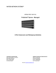
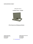
1
INSTALLATION GUIDE AND OPERATING MANUAL ProSwitch-Xtreme CORPORATE HEADQUARTERS 5001 American Blvd. W., Suite 605 Bloomington, MN 55437 Phone: 800.441.5319 MANUFACTURING/CUSTOMER SERVICE th 945 37 Avenue, NW Rochester, MN 55901 Phone: 800.328.2275 www.watersnet.com 12 ProSwitch- Xtreme User’s Manual (Managed Models) Page 1 TABLE OF CONTENTS 1.0 1.1 1.2 1.3 1.4 1.5 1.6 2.0 2.1 2.2 2.3 2.3.1 2.3.2 3.0 3.1 3.2 4.0 4.1 4.2 4.3 4.3.1 4.4 4.4.1 4.5 4.5.1 4.6 4.7 4.8 4.9 4.10 4.10.1 4.10.2 4.10.3 5.0 5.1 5.2 5.2.1 5.2.2 5.3 5.4 5.4.1 6.0 6.1 6.2 6.3 6.4 GETTING STARTED WITH SWITCH CONFIGURATION .................................................... 1 Equipment Required........................................................................................................................... 1 Brief Overview of the Console Management Interface ...................................................................... 1 Recommended Minimal Configuration .............................................................................................. 2 IP Address Configuration for Network Access .................................................................................. 2 IP Address Configuration Using DHCP............................................................................................. 2 Manual IP Address Configuration...................................................................................................... 3 MANAGING THE XTREME ......................................................................................................... 4 Using the CMI .................................................................................................................................... 4 System Configuration Menu............................................................................................................... 4 SNMP ................................................................................................................................................. 5 Bitview and Hubview ......................................................................................................................... 5 SNMP Management Features............................................................................................................. 5 UPGRADING THE XTREME SOFTWARE................................................................................ 6 Upgrading through Serial Console ..................................................................................................... 6 Upgrading through Network .............................................................................................................. 6 SOFTWARE CONFIGURATION ................................................................................................. 7 Port Menu ........................................................................................................................................... 7 Switch Configuration Menu ............................................................................................................... 7 Spanning Tree Protocol Configuration............................................................................................... 8 Menu Configuring STP from CMI ..................................................................................................... 9 VLAN Configuration ....................................................................................................................... 10 Port-Based Virtual LANs (Static VLANs)....................................................................................... 10 Quality of Service Configuration ..................................................................................................... 10 QoS Configuration from CMI .......................................................................................................... 11 Telnet................................................................................................................................................ 11 Auto-MDIX Support ........................................................................................................................ 11 Ageing Time..................................................................................................................................... 12 Broadcast Protection......................................................................................................................... 12 IP Address Configuration ................................................................................................................. 12 IP Address and Subnet Mask............................................................................................................ 13 Default Gateway Operation. ............................................................................................................. 13 Configuring IP Address, Gateway, DHCP ....................................................................................... 13 SECURITY FEATURES ............................................................................................................... 13 Manager and Operator passwords: ................................................................................................... 13 Console access interface and the CLI............................................................................................... 13 Manager............................................................................................................................................ 14 Operator............................................................................................................................................ 14 Password Security: ........................................................................................................................... 14 CMI: Setting Manager and Operator Passwords .............................................................................. 14 Configuring Manager and Operator Passwords ............................................................................... 14 TROUBLESHOOTING................................................................................................................. 15 Before Calling for Assistance........................................................................................................... 15 Return Material Authorization (RMA) Procedure............................................................................ 16 Shipping and Packaging Information ............................................................................................... 16 Warranty........................................................................................................................................... 17 12 ProSwitch- Xtreme User’s Manual (Managed Models) Page 2 1.0 Getting Started with Switch Configuration This section provides a quick overview so you can get your Xtreme switch up and running. It is targeted to Systems Administrators familiar with similar products. The procedure for assigning IP addresses and other vital configuration information required for basic operation of the switch will be provided. Detailed functions and procedures will be provided in the appropriate chapters of this manual. By default, the switch does not have a configured IP Address and all management access through the network is disabled. Since there is no IP by default, you must use the Console Management Interface (CMI). The CMI menu can be accessed through the console port (RS-232C standard 9 position D-Sub Connector) located on the right side of the front of the switch. 1.1 Equipment Required 1. Null Modem Cable, 9 Position D-Sub, Female to female 2. Computer with a functional RS-232C port (COMx: in PCs) 3. Terminal emulation program (e.g. HyperTerminal in Windows® platforms, Minicom in Linux ® platforms, or any other emulation software). Configure it for 38400 Baud, 8bit, No parity, and 1 stop bit (38400,8,N,1). If a flow control selection is available, select “No Flow control” Note: The baud speed is 9600 for version 1.0. 1.2 Brief Overview of the Console Management Interface The Console Management Interface (CMI) is a hierarchical menu based interface optimized for managing a switch with low port count. Each menu level provides a number of selections chosen by a single digit number entered at the keyboard to use that option or feature of the switch for configuration. 12 ProSwitch- Xtreme User’s Manual (Managed Models) Page 1 When a CMI session begins, the login screen is displayed. You have to enter a valid username and password combination to gain access to the CMI. There are two pre-defined user names, manager (password: manager) and operator (password: operator). The former allows access to all configuration options, while the latter allows only read access to the CMI. If a CMI session is idle for long durations, it will be reset and the Login screen will be displayed. If an IP address is not configured, the console shows a Warning Message. 1.3 Recommended Minimal Configuration If you don’t intend to use the management features of the Xtreme over the network connection, no special configuration steps are necessary. After login, you can navigate through the menu structure and access all management features available through the CMI 1.4 IP Address Configuration for Network Access An IP Address and associated parameters must be configured in order to enable access of the management functions through the network. The IP Address Configuration menu is available by selection 5 from the main menu. 1.5 IP Address Configuration Using DHCP The Xtreme supports Dynamic Host Configuration Protocol (DHCP) to obtain the IP Address from a server automatically. You will need a functional DHCP server in the network and the Xtreme must be connected to the network for this protocol to work successfully. The DHCP function is DISABLED by default. You will have to enable it in order to use it. Select 1 from the IP Configuration menu to enable DHCP. Then select 5 to save the changes 12 ProSwitch- Xtreme User’s Manual (Managed Models) Page 2 and reset the switch. The switch will go through the reset sequence and you will return to the login prompt. Login again and go to the IP Configuration menu. Make a note of the IP Address in use. This will be needed to access the switch from the network. ) ) Note: If Spanning Tree Protocol is enabled, the DHCP system will wait until the initial configuration of the Spanning Tree is complete before attempting to obtain an IP Address from the DHCP Server. The Login screen will alert on this status. Wait until the alert is gone to look for the IP Address. Note: If the DHCP Server lease to the IP Address could not be renewed after the expiry time, the system will disable the DHCP protocol and disable network access. No attempt will be made to look for DHCP servers after the expiration. The switch will have to be reset in order to restart the DHCP discovery. 1.6 Manual IP Address Configuration If you are not using DHCP, you will have to configure the IP Address manually. Please use the following procedure to configure the IP Address Parameters manually. Select 2 to enter the IP Address. The IP Address must be entered in the well known dotted quad format (like 192.168.1.1). The displayed IP Address will immediately change to the new value. However, the network stack will not use the new IP Address until the changes are saved and the switch is reset. Select 3 to enter the Netmask. The notation is similar to the IP Address Select 4 to enter the default gateway, if you will be accessing the switch from another network through a gateway. Select 5 to save the changes and reset the switch. The switch will go through the reset sequence and you will return to the login prompt. It is a good idea to go to the IP Configuration screen to make sure that the parameters are correct and the IP Address in use is the same as the IP Address you have configured. Please make note of the IP Address for future use. ) Note: If DHCP is ENABLED, the switch will first try to obtain an IP Address through DHCP. If the attempt is unsuccessful, the manually configured IP Address will be used. 12 ProSwitch- Xtreme User’s Manual (Managed Models) Page 3 Disable DHCP if you only want the manually configured IP Address to be used. The Xtreme will now be ready for use. 2.0 Managing the Xtreme The Xtreme has two management interfaces. As discussed in the above section, the Console Management Interface (CMI) is accessible through a console cable connection. The management interface an also be accessed through the Telnet protocol over the network. In either case, the user interface is exactly the same. Standards based Simple Network Management Protocol (SNMP) is available over the network. Appropriate client software is required to use this feature. Several software suites are available for this purpose. There is a GUI application which will work with the SNMPc suite by CastleRock (SNMPc 5.x or higher) software. 2.1 Using the CMI The CMI provides a simple hierarchical menu based interface for managing the Xtreme. ) Note: If Spanning Tree Protocol is enabled, the network access will not be available until the initial configuration is complete. This can take up to 30 seconds. Once you have logged into the switch, select a menu item by typing the appropriate selection number. The menu action initiates when the number key is pressed. It is not necessary to press the Enter Key. 2.2 System Configuration Menu The System Configuration menu allows the user to configure the system name, location and contact information. This information is used by the SNMP protocol to identify the managed device. It also allows the user to configure the community names to be used to access the SNMP agent. SNMP Traps can be configured by the Trap Configuration submenu. The resident software in the Xtreme can be upgraded from this menu. The following parameters, which are used by the SNMP management system, may be configured at this time. These are not mandatory for the operation of the switch, but provide identification for individual switches. 1. Select option 1 to enter system name. 2. Select option 2 to enter system location. 3. Select option 3 to enter system contact. The information entered here will be reported in the management information base of SNMP. If required, the community names (like passwords) to be used for accessing the management through SNMP can also be modified at this stage. 12 ProSwitch- Xtreme User’s Manual (Managed Models) Page 4 2.3 SNMP You can manage the switch via SNMP from a network management station. For this purpose, it is recommended to use the SNMPc, an easy-to-install and use network management platform that runs on Windows based PC’s. It uses the SNMP agent statistical sampling software that is included in the switch to provide powerful, but easy-to-use traffic monitoring and network activity analysis tools. 2.3.1 Bitview and Hubview The BitView and HubView can be seen through SNMPc (Management PC Software). Xtreme’s that have BitView and HubView definitions can be managed graphically. BitView displays a bitmap image that matches the faceplate of the device, whereas HubView is a more generic view that shows the layout of the device, but always uses the same picture elements. BitView is functionally similar to HubView, but displays a more realistic image of supported devices. Generally, all the LEDs and other graphical elements available on the device front panel can be displayed with BitView. As with HubView, you can select a device slot or port, and then a menu to operate on the selected item. Xtreme: Bitview Xtreme: Hubview 2.3.2 SNMP Management Features SNMP management features on the switch include: SNMP version 1 Security via configuration of SNMP communities Event reporting via SNMP 12 ProSwitch- Xtreme User’s Manual (Managed Models) Page 5 Supported Standard MIBs include: SNMP MIB-II (RFC 1213) Bridge MIB (RFC 1493) Version 1 traps (Warm Start, Cold Start, Link Up, Link Down, Authentication Failure,) Waters Proprietary MIB 3.0 Upgrading the Xtreme Software The Xtreme switch allows the software to be upgraded in the field. The software is available in the form of a binary file. It must be downloaded into the switch through the network connection or through the Serial Port Interface. ) Note: You must have the network parameters setup properly and Telnet access enabled in order to use the network to upgrade the software. Upgrading the software will not affect the device configuration. 3.1 Upgrading through Serial Console Use the following procedure to upgrade Xtreme software through the CMI. 1. Select option 1 to go to The System Configuration screen. 2. Select option 8 to upgrade software 3. Answer Y to confirm upgrade action. The switch will prompt to send the binary file through XMODEM protocol (By default through Serial Console). Initiate XMODEM download from your terminal program (e.g. Hyper Terminal or other emulation). An example of accessing an emulation follows: For Hyper Terminal: From the Menu, Select Transfer -> Send File -> a small popup window opens... use Browse button to locate your path to the MNS Software file (e.g.Rel1.0.bin) location, and select the protocol as Xmodem from the drop down list, then click Ok. (For other emulations, please check your Operating System Software User’s Guide). The download should start and proceed to download the file. The System will reboot after successful upgrade and will come back to the Login prompt. NOTE: Please do not interrupt the switch or the Desktop PC during the download process. You can safely terminate the download anytime and the existing version of the software will continue to be used. Once download is complete, the switch will check the integrity and signature of the binary file. If it is found to be a certified Xtreme binary file with no errors, it will be copied to the Flash memory. The switch will then be reset to start the newly upgraded software. 3.2 Upgrading through Network Use the following procedure to upgrade Xtreme software through the Network 12 ProSwitch- Xtreme User’s Manual (Managed Models) Page 6 Use the Telnet client to connect to the switch. You will need the IP address of the switch to in order to access the switch via Telnet. The Telnet session resembles the CMI session in all respects. Login using the username manager and the appropriate password (Default password is manager). Use the following procedure to upgrade Xtreme software through the Network (Remote upgrade). 1. 2. 3. 4. Select option 1 to go to The System Configuration screen. Select option 8 to upgrade software Answer Y to confirm upgrade action. The switch will prompt to send the binary file through TFTP protocol. You have to use the PUT method of TFTP protocol (on TFTP Client) to send the file to the switch. You can safely terminate the download anytime, and the existing version of the software will continue to be used. Once download is complete, the switch will check the integrity and signature of the binary file. If it is found to be a certified Xtreme binary file with no errors, it will be copied to the Flash memory. The switch will then be reset to start the newly upgraded software. 4.0 Software Configuration 4.1 Port Menu The Port menu displays the status of the ports. You can enter the port number for detailed information on the port in another screen. Various port parameters can be configured from the port configuration screen. ) Note: All configurations are stored in non-volatile memory, so that the switch boots up with the configurations enabled. This can sometimes lead to confusion, when ports are accidentally disabled. Always check the configuration of the ports and the VLAN configuration if a port appears to not be communicating. 4.2 Switch Configuration Menu The Switch Configuration Menu allows the user to set various parameters associated with the switch engine. The Spanning Tree Protocol configuration and VLAN configuration are 12 ProSwitch- Xtreme User’s Manual (Managed Models) Page 7 available through their own submenu. The port map for the Link-Loss Learn facility is configured from this menu 4.3 Spanning Tree Protocol Configuration The Xtreme implements the Spanning Tree Protocol (STP) as defined in IEEE 802.1D standard. STP ensures that only one network path is active between any two nodes. If more than one physical path exists between any two nodes, the STP will ensure a single active path by blocking all redundant paths. More than one active path between nodes will result in loops. A packet getting into the loop will pass around the loop infinitely, resulting in what is termed as a “broadcast storm” which will bring the network down. STP is necessary in such situations to avoid loops. When the switch is powered ON, all ports are set to disabled state. The STP then arrives at an active configuration by passing messages around the network. The configuration is continuously monitored and updated by passing messages. By default, STP will take 30 seconds to finish the initial configuration. The switch will not pass traffic during this time period. STP has the following parameters for configuration: 12 ProSwitch- Xtreme User’s Manual (Managed Models) Page 8 There are system parameters that affect the whole switch. The following system parameters are available for the Xtreme switch Parameter priority Default 32768 Range 0 - 65535 maximumage 20 seconds 6 – 40 seconds hello-time 2 seconds 1 - 10 forwarddelay 15 seconds 4 – 30 seconds Description Specifies the priority value used along with the switch MAC address to determine which device is root. The lower a priority value, the higher the priority. Maximum received message age the switch allows for STP information before discarding the message, Time between messages transmitted when the switch is the root. Time the switch waits before transitioning from the listening to the learning state, and between the learning state to the forwarding state. Port Parameters affect individual ports. The following are the port parameters available for the Xtreme switch 4.3.1 Parameter path-cost Default 100 Range 1 - 65535 priority 128 0 - 255 Description Assigns an individual port cost that the switch uses to determine which ports are the forwarding ports. Used by STP to determine the port(s) to use for forwarding. The port with the lowest number has the highest priority. Menu Configuring STP from CMI The values of the parameters, both currently set and the actual value in use, are displayed in the menu screen. All the switches participating in the Spanning Tree use the parameters offered by the root node. The root node is elected by comparing the priority value and the MAC address of all the nodes participating in the Spanning Tree. The port parameters are configured from the appropriate port menu. 12 ProSwitch- Xtreme User’s Manual (Managed Models) Page 9 4.4 VLAN Configuration 4.4.1 Port-Based Virtual LANs (Static VLANs) A VLAN is a group of ports designated by the switch as belonging to the same broadcast domain. (That is, all ports carrying traffic for a particular subnet address would normally belong to the same VLAN.) The VLAN Configuration submenu allows configuration of up to four port based Virtual LANs. When VLAN is enabled, a port can communicate with another port only if both are members of the same VLAN. The VLAN membership is entered as a port map as a string containing the port numbers. The system will scan the string and create a port map using the numbers found in the string. The map can be deleted by entering an empty string. For example, the string 13567, deletes ports 2,4 and 8. All ports will return to normal mode of operation when the VLAN operation is disabled. The VLAN port maps are, however, remembered and can be brought to effect when the VLAN operation is enabled later. Note: Maximum four VLANs can be configured. 4.5 Quality of Service Configuration The Xtreme switch offers Quality of Service (QoS) as specified in IEEE 802.1p standard. Each port of the Xtreme has a packet buffer into which the packets destined for that port are placed. The packets in the buffer are then transmitted in a first-in first-out basis. This can create problems by ‘delaying critical’ traffic like audio and video streaming. When QoS functionality is enabled, the packet buffer for the ports are divided into two. One is treated as high priority and the other as low priority. Packets placed in the high priority buffer will be given preference over those in the low priority buffer for transmission. The switching engine prioritizes each packet and places it in the appropriate buffer. The priority of a packet can be decided in two ways. The user can specify a particular port to be of high/low priority or a particular packet can be marked as high/low priority using a special tag field inserted into it. The Xtreme switch engine will identify the priority from these and place the packet in the appropriate buffer. 12 ProSwitch- Xtreme User’s Manual (Managed Models) Page 10 4.5.1 QoS Configuration from CMI The CMI provides two controls for QoS. The QoS functionality can be enabled or disabled from the Switch Parameters menu. The priorities associated with the individual ports are configured from the individual port menu. 4.6 Telnet The Telnet protocol is often thought of simply as a provider for remote logins to computer via the Internet. This was its original purpose although it can be used for many other purposes. It is best understood in the context of a user with a local computer accessing the local Telnet program (known as the client program) to run a login session on a remote computer where his communication needs are handled by a Telnet server program running on the remote computer. It should be emphasized that the Telnet server can pass on the data it has received from the client to many other types of processes including a remote login server. You can disable or enable the Telnet access though CMI. 4.7 Auto-MDIX Support Xtreme supports Auto-MDIX for all the RJ45 Ports globally. MDI/MDIX is a type of Ethernet port connection using twisted pair cabling. The MDI (for medium dependent interface) is the component of the media attachment unit (MAU) that provides the physical and electrical connection to the cabling medium. An MDIX (for MDI crossover) is a version of MDI that enables a connection between like devices. MDI ports connect to MDIX ports via straight-through twisted pair cabling; both MDI-to-MDI and MDIX-to-MDIX connections use crossover twisted pair cabling. You can disable or enable the Auto-MDIX support though CMI for RJ45 Ports. 12 ProSwitch- Xtreme User’s Manual (Managed Models) Page 11 4.8 Ageing Time Users can select the Address table Ageing Time between 10–1000000. The default value is 300. 4.9 Broadcast Protection One of the best features of the Xtreme is its ability to keep broadcast storms from spreading throughout a network. Network storms are characterized by an excessive number of broadcast packets being sent over the network. These storms can occur if network equipment is configured incorrectly, network software is not properly functioning, or poorly designed programs (including some network games) are used. Storms can reduce network performance and cause bridges, routers, workstations, servers and PC's to slow down or even crash. A User can set the Broadcast Filter Percentage (0-100, 0 to Disable). The default value is 50%. 4.10 IP Address Configuration The IP Address configuration menu allows the user to configure the network address of the Xtreme. This is required to enable network access to the device. The values are entered in dotted quad notation. Null IP Address (0.0.0.0) cannot be entered as a value. Only in this menu, the entered values do not take effect until the values are saved and the switch reset by menu selection 5. You can discard the values by choosing 0. 12 ProSwitch- Xtreme User’s Manual (Managed Models) Page 12 ) Note: If you are accessing the CMI through the network, and if the IP Address is changed, your connection will be terminated and you will have to initiate another Telnet session to the new IP Address. 4.10.1 IP Address and Subnet Mask. By default, the switch is set to manual IP addressing. To set a manual IP address, use the CLI to configure the initial IP values. If you want to configure the IP automatically, then enable the DHCP/Bootp server that has been set correctly with information to support the switch. The IP will auto configure. 4.10.2 Default Gateway Operation. The default gateway is required for tasks such as reaching off-subnet destinations or forwarding traffic across multiple VLANs. The gateway value is the IP address of the nexthop gateway node for the switch, which is used if the requested destination address is not on a local subnet/VLAN. If the switch does not have a manually-configured default gateway and DHCP/Bootp is configured, then the default gateway value provided by the DHCP or Bootp server will be used. If the switch has a manually configured default gateway, then the switch uses this gateway. 4.10.3 Configuring IP Address, Gateway, DHCP Do one of the following: 1. To manually enter an IP address and subnet mask, set the IP Config parameter to Manual and then manually enter the IP address and subnet mask values you want for the switch. OR 2. To use DHCP or Bootp, Enable it choosing option 1. Restart the switch. The Xtreme will obtain an IP address from the DHCP server. 5.0 Security Features 5.1 Manager and Operator passwords: You can obtain access and privileges for the menu interfaces through either the Console connection or the network by using Telnet. 5.2 Console access interface and the CLI. There are two levels of console access: Manager and Operator. For security, you can set a password on each of these levels. 12 ProSwitch- Xtreme User’s Manual (Managed Models) Page 13 5.2.1 Manager This level allows access to all console interface areas. Please change the default Manager Password (Default password is manager) to limit access of unauthorized people to the configuration area of the console interface. 5.2.2 Operator This level allows access to the Status but does not allow Configuration capabilities. On the Operator level, the Configuration Context, Download Application, and Reboot Switch option are not accessible. 5.3 Password Security 1. Set a Manager password (and an Operator password, if applicable for your system). 2. Exit from the current console session. 3. A Manager password will now be required for full access to the console. Assuming that both a Manager password and an Operator password have been set, the level of access to the console interface will be determined by which password is entered in response to the prompt. The manager and operator passwords control access to the CMI. Note: Passwords are case sensitive. 5.4 CMI: Setting Manager and Operator Passwords Users can change or reset the Administrator (Manager) and user passwords through option 4. 5.4.1 Configuring Manager and Operator Passwords This procedure prompts you to enter a password twice to help verify that you have correctly entered the desired characters. User can modify the Administrator password (Option 1) or User Password (Option 2) through this menu. 12 ProSwitch- Xtreme User’s Manual (Managed Models) Page 14 6.0 Troubleshooting All Waters’ switching products are designed to provide reliability and consistently high performance in all network environments. The installation of Waters’ Xtreme switch is a straightforward procedure discussed in this manual. Should problems develop during installation or operation, this section is intended to help locate, identify and correct these types of problems. Please follow the suggestions listed below prior to contacting your supplier. However, if you are unsure of the procedures described in this section or if the ProSwitch- Xtreme switch is not performing as expected, do not attempt to repair the unit; instead contact your supplier for assistance or contact Waters Network Systems’ Customer Support Center at 800.328.2275 or email [email protected]. 6.1 Before Calling for Assistance 1. If difficulty is encountered when installing or operating the unit, refer back to the Installation Section of the chapter of this manual. Also check to make sure that the various components of the network are inter-operable. 2. Check the cables and connectors to ensure that they have been properly connected and the cables/wires have not been crimped or in some way impaired during installation. (About 90% of network downtime can be attributed to wiring and connector problems.) 3. Make sure that an AC power cord is properly attached to the power supply and the power supply is properly attached to the switch. 4. Be certain that each AC power cord is plugged into a functioning electrical outlet. Use the PWR LEDs to verify each unit is receiving power. 5. If the problem is isolated to a network device other than the Waters’ ProSwitchXtreme switch, it is recommended that the problem device be replaced with a known good device. Verify whether or not the problem is corrected. If not, go to next step. If the problem is corrected, the Waters’ ProSwitch- Xtreme switch and its associated cables are functioning properly. 6. If the problem continues, contact Waters Network Systems Customer Service at 800.328.2275 or email [email protected] for assistance. When Calling for Assistance: Please be prepared to provide the following information. 1. 2. 3. 4. 5. 6. A complete description of the problem, including the following points: The nature and duration of the problem Situations when the problem occurs The components involved in the problem Any particular application that, when used, appears to create the problem An accurate list of Waters Network Systems product model(s) involved. Include the date(s) that you purchased the products from your supplier. 7. It is useful to include other network equipment models and related hardware, including personal computers, workstations, terminals and printers; plus, the various network media types being used. 8. A record of changes that have been made to your network configuration prior to the 12 ProSwitch- Xtreme User’s Manual (Managed Models) Page 15 occurrence of the problem. Any changes to system administration procedures should all be noted in this record. 6.2 Return Material Authorization (RMA) Procedure All returns for repair must be accompanied by a Return Material Authorization (RMA) number. To obtain an RMA number, call Waters Network Systems Customer Service at 800.328.2275 during business hours from 8:00 am to 5:00 pm (CT) email [email protected]. When calling, please have the following information readily available: 6.3 Name and phone number of your contact person Name of your company/institution Your shipping address Product name Packing List Number (or Sales Order Number) Failure symptoms, including a full description of the problem Waters Network Systems will carefully test and evaluate all returned products, will repair products that are under warranty at no charge, and will return the warranty-repaired units to the sender with shipping charges prepaid (see Warranty Information, Appendix A, for complete details). However, if Waters cannot duplicate the problem or condition causing the return, the unit will be returned as: No Problem Found. Waters Network Systems reserves the right to charge for the testing of nondefective units under warranty. Testing and repair of product that is not under warranty will result in a customer (user) charge. Shipping and Packaging Information Should you need to ship the unit back to Waters Network Systems, please follow these instructions: Package the unit carefully. It is recommended that you use the original container if available. Units should be wrapped in a "bubble-wrap" plastic sheet or bag for shipping protection. (You may retain all connectors and this Installation Guide.) CAUTION: Do not pack the unit in Styrofoam "popcorn" type packing material. This material may cause electro-static shock damage to the unit. Clearly mark the Return Material Authorization (RMA) number on the outside of the shipping container. Waters Network Systems is not responsible for your return shipping charges. Ship the package to: Waters Network Systems Attention: Customer Service RMA Number: 945 37th Avenue, NW Rochester, MN 55901 12 ProSwitch- Xtreme User’s Manual (Managed Models) Page 16 6.4 Warranty Waters Network Systems makes no express or implied warranties including, but not limited to, any implied warranty of merchantability or fitness for a particular purpose, except as expressly set forth in this warranty. In no event shall Waters Network Systems be liable for incidental or consequential damages, costs, or expenses arising out of or in connection with the performance of the product delivered hereunder. Waters Network Systems will in no case cover damages arising out of the product being used in a negligent fashion or manner. For additional Waters’ warranty information, please contact Customer Service at 800.328.2275 during business hours from 8:00 am to 5:00 pm (CT) or email [email protected]. 12 ProSwitch- Xtreme User’s Manual (Managed Models) Page 17