1
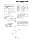
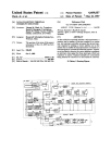
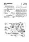
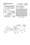
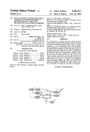
United States Patent [19]
[11] Patent Number:
Samuels et al.
[45]
[54] PROCESSOR WITH SPEED INDEPENDENT
5,065,173
Date of Patent:
[56]
Nov. 12, 1991
References Cited
FIXED FILM SPACING
us. PATENT DOCUMENTS
[75] Inventors: James T. Samuels; Roger D,
4,057,817 11/1987 Korb et a1. ........................ .. 354/298
Ellsworth, both of Rochester,
4,300,828 11/1981
Kaufman ...... ..
.
.... .. 354/322
.
_'
[73] Asslgnee' Eastman Kodak Company’
Rochester, N.Y.
Primary Examiner—A. A. Mathews
Attorney, Agent, or Firm-G. Herman Childress
[21] Appl' No‘: 495’867
[22] Filed.
Mm, 19 1990
An automatic ?lm processor sets new reference devel
oper chemical temperatures and ?lm transport speeds in
[57]
-
'
’
ABSTRACT
accordance with user input at a keypad and establishes
a new delay time to provide constant ?xed spacing
Related U.S. Application Data
[63}
along the transport path between trailing edge of one
Continuatiomimpm of sen NO. 494,647, Man 16,
1990, Pat_ No_ 4,994,331
?lm sheet and lead?ngedge of a next ?lm sheet regard.
less of transport speed. “Wait” and “ready” lights are
controlled to signal when a next sheet is to be fed. A
[51] Int. Cl.5 ............................................. .. G03D 3/08
microcomputer calculates the delay time and loads a
[52]
[58]
counter- A buzzer signals countdown to zero.
US. Cl. ............................ .. 354/298; 354/322
Field of Search ............. .. 354/298, 319, 320, 321,
354/322
14 Claims, 3 Drawing Sheets
6/
g27
I
CLOCK
“state
SENSOR
I
<26
m
H
COUNTER
--1
SENSOR
£37
§50
——
1
__
Q44
S'Q‘IDT‘JCEH
<43
(:7
MICROCOMPUTER
OVERRIDE
SWITCH
TEMPERATURE
SENSOR
36‘
Q
g9
‘52
HEATER
HEATER
CONTROL
>——
BUZZER
5/
""
g
(48
MOTOR
<53
CONTROL
__
SHAFT
SPEED
SENSOR
ANNUNCIATOR
CONTROL
rm
30)
_
‘
54
ROLLERS
34
55
TRANSPORT
33
US. Patent
Nov. 12, 1991
Sheet 2 of 3
5,065,173
FIE-‘m3
k
> <
+
I07
NO
YES (08
DESIGNATE
NEW REF. SPEED
I
LOAD COUNTER
WITH
SPACING TIME
Q03
A
DESIGNATE NEW
SPACING TIME
coum
/04
SET SPACING
T|ME=NEW
SPACING TIME
‘
YES (Ill .
v
n
'r
.
COUNT =
=0 ER
TURN OFF "WAIT"
a
/05
NO
TURN ON "READY"
V
gl/Z
souwo
YES 5/06
BUZZER
TURN Oél "WAIT"
TURN OFF "READY"
FIEQS
COUNT+I
US. Patent
Nov. 12, 1991
Sheet 3 0f 3
5,065,173
hmoawzqkmEwJOI
S
mm
I856 D3km
53
wo5:38 _-S0E5 _512586
B
m»
“11%w
‘ @062E26
RV
il ?
.6528
50.6
vn
_
mO Zwm
ImJO
1
5,065,173
2
ing may be controlled by a ?xed set time interval be
PROCESSOR WITH SPEED INDEPENDENT
FIXED FILM SPACING
tween the entry into the processor of the trailing edge
of the ?rst sheet and the time when the user is signalled
to enter the next sheet. When the entry of the leading
edge of the ?rst sheet into the processor is detected, an
annunciator in the form of a “wait” light is illuminated
This is a continuation-in-part of commonly owned,
copending US Pat. application Ser. No. 07/494,647,
?led Mar. 16, 1990, now U.S. Pat. No. 4,994,837, enti
tled “Processor With Temperature Responsive Film
Transport Lockout.”
BACKGROUND OF THE INVENTION
The present invention relates to processors of ?lm
to signal that the required spacing has not yet been
attained. At a set time after the entrance of the trailing
edge into the processor has been detected, the “wait”
i0
light is extinguished and a “ready” light is illuminated.
Although conventional processors used for radio
graphic image processing are traditionally con?gured
and similar photosensitive media, in general; and, in
to operate at a constant ?lm transport speed, modi?ca
particular, to a processor having means to vary trans-~
port speed and including means to maintain ?xed inter
tions may be made through gear changes and the like to
vary the process. Moreover, new processors are being
?lm spacing regardless of transport speed.
introduced which are usable in more than one mode.
Photosensitive media processors, such as the Kodak
X-OMAT processors, are useful in applications such as
The mode is often referred to in shorthand fashion by a
nominal ?lm transport “drop time”, which may be de
?ned as the time from entry of the leading edge of a
sheet of ?lm at the feed end until exit of the trailing edge
of the same sheet of ?lm at the discharge end. Conven
the automatic processing of radiographic ?lms for med
ical imaging purposes. The processors automatically
transport sheets or webs of photosensitive ?lm, paper or
the like (hereafter “?lm”) from a feed end of a ?lm
transport path, through a sequence of chemical process
tional processors operate in standard (90 second), rapid
(45 second), or “Kwik” (30 second) mode, and can be
ing tanks in which the media is developed, ?xed, and
varied to operate in an extended-cycle mode, such as
washed, and then through a dryer to a discharge or 25 described in L. Taber & A. G. Hans, “Processing of
receiving end. The processor typically has a ?xed ?lm
Mammographic Films: Technical and Clinical Consid
path length, so final image quality depends on factors
including transport speed which determines length of
eration," Radiology, Vol. 173, No. 1, pages 65-69, Oct.
cessor “chemistry”).
In a typical automatic processor of the type to which
the invention relates, ?lm transport speed is set at a
tissue. The new processors will be settable as to run
1989. In the latter mode, processor speed is lowered and
time the ?lm strip is in solution, and the temperature
chemistry temperature is raised to enhance image con
and composition of the processing chemicals (the pro 30 trast for better detection of changes in density of ?brous
parameters, including transport speed in order to be
able to use the same processor for multiple processing
modes.
constant rate and the chemistry is de?ned according to
a preset recommended temperature, e.g. 93° F., with a 35
speci?ed tolerance range of +/-X° F. A temperature
control system is provided in the processor to keep the
chemicals within the speci?ed range.
It is desirable, in a processor having selectable trans
port speed, to be able to maintain a ?xed inter?lm spac
ing during transport regardless of the transport speed
setting. Conventional systems that operate on a ?xed
time interval to determine ?lm spacing are inadequate
for this purpose. When faster transport speeds are se
Conventional processors usually include a ?lm width
sensor in the form of a reflective infrared sensor array
adjacent a feed entrance opening, and may also include
lected, the same ?xed time interval will give a spacing
that is too great. When slower transport speeds are
like for detecting separation of entrance rollers due to
selected, the same interval will give a spacing that is too
the passage of ?lm sheets at the front end of the trans
small.
portation path. The ?lm width sensor not only provides 45 One prior art arrangement, described in U.S. Pat. No.
an indication of the width of a sheet entering the proces
4,300,828, sets spacing using a feed counter clocked by
sor, but may also provide an indication of the occur
a drive shaft encoder. A microcomputer loads the feed
rence of the leading edge and trailing edge of each
counter with a number corresponding to the number of
sheet, since the signals from the ?lm width sensor will
shaft encoder pulses needed to drive the trailing edge of
a feed detector in the form of a Hall effect switch or the
change signi?cantly as each leading and trailing edge is
50
the sheet past a particular point of the transport path.
encountered. Information as to leading and trailing edge
occurrences and width of the ?lm, taken with prior
knowledge of the constant transport speed, is used to
keep track of cumulative total ?lm surface area pro
cessed in order to guide chemistry replenishment con 55
When the count reaches zero, a feed annunciator is
actuated and a “wait” light is turned off. There is no
teaching or recognition in the ‘828 patent of using such
a shaft encoder system in a processor whose transport
trol. The use of a separate entrance roller detector sig
speed is settable. Moreover, the mechanical nature of
the encoder limits programming flexibility.
nals that a sheet of ?lm has actually entered the nip of
the ?rst roller pair, and is not just sitting still on the ?lm
guide under the width sensor.
SUMMARY OF THE INVENTION
It is an object of the present invention, in a processor
When sheets of ?lm are sequentially fed into a proces 60 utilizing a ?xed time period between trailing edge of a
sor, it is desirable that a spacing be maintained between
?rst sheet and leading edge of a second sheet, to provide
the trailing edge of a ?rst sheet and a leading edge of a
a system for varying the ?xed time in response to varia
next one in order to avoid overlap. The spacing should
tion in transport speed, so as to maintain a ?xed inter
be enough so that overlap is avoided even though one
?lm spacing to avoid overlap regardless of ?lm trans
or both of the sheets suffer some slippage and/or skew 65 port speed.
ing along the transport path, but not so great that pro
It is another object of the present invention to pro
cessing time is unduly affected. For a particular con
vide an annunciator to signal the attainment of recom
stant ?xed transport speed processor, proper ?lm spac
mended ?lm sheet spacing in an automatic processor
3
5,065,173
4
con?gured to operate at a plurality of ?lm transport
24 comprising oppositely-disposed pluralities of air dis
speed settings.
pensing tubes 25 or some other appropriate ?lm drying
mechanism.
Positioned proximate opening 15 is a sensor 26, such
In accordance with the invention, a processor of
exposed photosensitive media having means for auto
matically transporting ?lm along a path through devel
oper, ?xer, wash and dryer stations and means for moni
toring the entrance of a trailing edge of a particular
medium into the processor, further comprises means
responsive to user input for setting system parameters
including a desirable transport speed, and means for
determining and signalling the passage from entrance of
that trailing edge to the time to feed the next medium at
a desired ?xed optimum spacing.
In one aspect of the invention, described in greater
detail below, processor ?lm transport speed is set ac
cording to user selection of a processor operating mode,
and annunciators in the form of “ready” and “wait”
lights are controlled in accordance with a determination
of lead time needed to assure maintenance of a desired
linear spacing between successive sheets of ?lm, for the
particular processor mode setting. A microcomputer
determines the number of clock counts to be loaded into
a counter responsive to setting of the transport speed.
BRIEF DESCRIPTION OF THE DRAWINGS
Embodiments of the invention have been chosen for
purposes of illustration and description and are shown
in the accompanying drawings, wherein:
FIG. 1 is a perspective view of a processor in which
as a conventional universal ?lm detector board, re?ec
tive infrared sensor array which provides signals indica
tive of sheet width when a sheet F1, F2 is presented at
the entrance opening 15. The ?lm width sensor 26 also
provides an indication of the occurrence of passage of
the leading edge and trailing edge of each sheet past
point 26 of the processor 12. A second sensor 27, in the .
form of a magnetic reed switch 29 or the like (FIG. 3),
may be provided to detect separation of entrance rollers
28 to signal the beginning of transportation of a sheet of
?lm along the path 16. Sensor 27, as shown, is a Hall
effect sensor and has an actuator or slug 32 mounted on
a rocker arm 36 for movement about a pivot pin 37,
from the solid line to the dot-dashed line position, in
response to separation of the upper entrance roller 28a
from the lower entrance roller 28b. Other sensors may
also be used.
In FIG. 2, the sheet path 16 is shown as de?ned by a
plurality of ?lm transport rollers 30 and a plurality of
guide shoes 31 located to direct a sheet of ?lm F sequen
tially through the tanks 21, 22, 23 and dryer 24. The
rollers 30 form the transport system for transporting the
sheets F1, F2 through the processor 12. Crossover as
semblies act at the interfaces between the respective
tanks 21, 22, 23 and dryer 24 to transport sheets between
the corresponding stations. Rollers 30 may be driven in
conventional manner by a common drive shaft 33 (FIG.
a ?xed ?lm spacing system in accordance with the pres
ent invention can be employed;
FIG. 2 is a schematic representation of relevant ele
4) having alternating right-hand and left-hand axially
ments of the processor of FIG. 1;
spaced worms for driving adjacent columns of rollers
FIG. 3 is a fragmentary view of an entrance roller
30 at the same speed in counterrotation, so as to move
detector usable in the processor of FIGS. 1 and 2;
35 the sheets F1, F2 in the direction of the arrows along
FIG. 4 is a block diagram of the ?xed ?lm spacing
path 16. Drive shaft 33 may be connected by a no slip
system employed in the processor of FIGS. 1 and 2; and
chain drive and toothed sprockets (not shown) to be
FIG. 5 is a flow diagram of the operation of the sys
driven by an electric motor 34 such as, for example, a
tem of FIG. 4.
variable speed brushless DC motor.
Throughout the drawings, like elements are referred
The temperature of developer chemical in tank 21
to by like numerals.
may be controlled by means of a recirculation plumbing
DETAILED DESCRIPTION OF THE
PREFERRED EMBODIMENTS
path 35 (FIG. 2) having a pump P for drawing devel
oper out of tank 21, through a thermowell or other
suitable heater and ?lter, and then passing it back to the
The principles of the invention are illustrated, by way 45 tank 21. A temperature sensor 37 (FIG. 4) is provided in
of example, embodied in the form of a ?xed ?lm spacing
the tank 21 or recirculation path 35 to monitor the tem
system 10 (FIG. 4) suitable for use with a processor 12
perature of the developer. Developer temperature may
(FIGS. 1 and 2) for the automatic processing of photo
be displayed on a meter 41 located on an exterior con
sensitive media in the form of successive sheets of ?lm
trol panel 42 of the processor 12. Temperature control
F1, F2 (FIG. 2), such as for the development of radio 50 of ?xer chemistry may be conveniently provided by
graphic images for medical diagnostic purposes.
passing an immersed loop 39 through the ?xer tank 22.
The processor 12 has a feed shelf 14 positioned ahead
FIG. 4 illustrates a control system usable in imple
of an entrance opening 15 (FIG. 2). The front end of the
menting an embodiment of the present invention. As
processor 12 including feed shelf 14 and entrance open
shown in FIG. 4, a microcomputer 43 is connected to
ing 15 is located in a darkroom to avoid unwanted expo 55 direct the operation of the processor 12. Microcom
sure of the sheets F1, F2 fed into the processor 12. The
puter 43 receives manual input from the user through a
remaining portion of the processor 12 may be outside
mode switch 44 as to what processor mode of operation
the darkroom. Sheets F1, F2 entered through entrance
is desired. The system can be con?gured to enable the
opening 15 are transported through the processor 12
user to select among predesignated modes, such as stan
along a travel path 16 (indicated by arrows), and are 60 dard, rapid, “Kwik," or extended modes having prede
eventually driven out of the back end of processor 12
termined associated ?lm path speed and chemistry tem
into a catch bin 17 at an exit opening 18.
perature parameters; and can also be con?gured to per
The processor 12 includes a developing station com
mit a user to set a desired path speed and temperature
prising a tank 21 ?lled with developer chemical; a ?xing
directly. One way to implement mode switch 44 is by
station comprising a tank 22 ?lled with ?xer chemical; 65 means of an alphanumeric keypad 45 and keypad dis
and a wash station comprising a tank 23 ?lled with wash
water or comprising some other appropriate ?lm wash
ing device. Processor 12 also includes a drying station
play 46 (FIG. 1) for providing programming communi
cation between the user and the microcomputer 43. For
example, a function code can be entered to signal that
5
5,065,173
6
mode selection is being made, followed by a selection
code to designate the selected mode. Alternatively, a
ing edge of a ?rst sheet F1 and leading edge of a second
sheet F2, needed to achieve a predetermined desired
function code can be entered for ?lm path speed or
?xed spacing (103, 104).
chemistry temperature, followed by entry of a selected
speed or temperature setting. Another way to imple
edge of a ?rst sheet F1 and the leading edge of a second
ment switch 44 is by means of a plurality of push button
or toggle switches, respectively dedicated one for each
following algorithm:
selectable mode, and which are selectively actuated by
the user in accordance with user needs.
The time in seconds required between the trailing
sheet F2 may, for example, be determined using the
Time (secs) = ((L/ V) X 60 secs/min)/ 100
Microcomputer 43 is also connected to receive input 10
information from the ?lm width sensor 26, the entrance
roller sensor 27, the developer temperature sensor 37
and, optionally, from a shaft speed sensor 48. Shaft
where L=inter?lm spacing in inches><l00; and
V=?lm velocity in inches/minute.
Using a desired linear sheet spacing of three inches,
speed sensor 48, which may comprise a shaft encoder
the delay time desired to maintain a constant linear
mounted for rotation with drive shaft 33 and an associ
ated encoder sensor, provides feedback information
about the speed of the common shaft 33 that uniformly
separation between sheets F1, F2 along path 16 for
drives the transport rollers 30 (FIG. 2). This gives the
speed with which ?lm is driven along the ?lm transport
path 16. The width sensor 26 provides the microcom 20
puter 43 with information on the leading and trailing
edge occurrences and the width of the ?lm sheets F1,
F2. This can be used together with microprocessor set
?lm speed or ?lm speed measured by sensor 48 to give
different given transport speeds is as follows:
V (in/min)
time (secs)
30
40
50
60
70
80
90
lOO
l 10
120
a cumulative ?lm development area total to control 25
chemistry replenishment. The entrance roller sensor 27
6
4.5
3.6
3
2.57
2.25
2.0
1.8
1.63
L5
signals when a ?lm sheet leading edge has been picked
up by the roller path 16, or when a trailing edge has
passed a certain point in path 16. This information can
be used together with transport speed and known 30 The delay times can also be set using a preestablished
length of the path 16 from entrance rollers 28 to exit
rollers 50 (FIG. 2), to indicate when a sheet of ?lm is
look-up table.
present along the path 16.
When the sensors 26 and/or 27 detect the passage of
the leading edge of a ?rst sheet F1 into the processor 12
speed of rotation of drive shaft 33. This controls the
loading of a counter 60 (FIG. 4) with a number corre
(105), annunciator control circuit 53 is directed by mi
Microcomputer 43 is shown in FIG. 4 connected to
motor control circuitry 51, heater control circuitry 52, 35 crocomputer 43 to turn the “wait” light 54 on, and the
“ready” light 55 off (106). When the trailing edge of
and annunciator control circuitry 53. Motor control
sheet F1 is detected (107), microcomputer 43 directs the
circuitry 51 is connected to motor 34 to control the
sponding to the number of pulses of a system clock 61
16 and, thus, determines the length of time a sheet 40 needed to give the required sheet separation time in
seconds determined in response to the selection of trans
spends at each of the stations (viz. controls development
port speed (108). When the count in counter 60 reaches
time). Heater control circuitry 52 is connected to con
zero (109, 110), the “wait” light is turned off and the
trol the temperature of the developer ?owing in the
“ready” light turned on (111). This indicates to the user
recirculation path 35 (FIG. 2) and, thus, the tempera
ture of developer in tank 21 and ?xer in tank 22. Annun 45 that the sheet F1 has passed a point where the next sheet
F2 can be fed into the processor.
ciator control circuitry 53 is connected to annunciators
speed of travel of ?lm sheets F1, F2 along the ?lm path
in the form of "Wait” light 54 and “Ready” light 55 to
As shown in FIG. 5, if counter 60 is not at zero, the
control the on/off cycles of the same. Identical “Wait”
“wait” light 54 remains on and the “ready” light 55
remains off (109). When the counter 60 reaches zero,
the “wait" light 54 is then switched off and the “ready”
light 55 is switched on (111).
and “Ready” lights 54, 55 (for example, LED’s) may be
provided on both the darkroom (not shown) and light
room (see control panel 42 in FIG. 1) sides of the pro
cessor 12.
_
Other annunciators, such as a buzzer 58, can be con
In accordance with the invention, as indicated in the
nected to the microcomputer 43 to be actuated when
?ow diagram of FIG. 5, a user-designated mode change
ever counter 60 reaches zero to indicate a “ready” con
selected at keypad 45 (FIG. 1) or other mode switch 44 55 dition exists and a fresh sheet F2 can be fed in at en
trance 15 (112).
(FIG. 4) is input to microcomputer 43 (100) to cause a
Those skilled in the art to which the invention relates
designation (through look-up table, algorithm or the
will appreciate that other substitutions and modi?ca
like) of reference developer temperature and transport
tions can be made to the described embodiments with
speed parameters recommended for the selected mode
(102). Motor and heater control circuits 51, 52 are then 60 out departing from the spirit and scope of the invention
as described by the claims below.
directed to control the motor and heater to bring the
actual developer temperature and ?lm path transport
speed into line with the designated reference tempera
What is claimed is:
'
1. In apparatus for the processing of exposed photo
ture’ and speed. The system can be con?gured, if de
sensitive media, said apparatus having means for auto
sired, to permit the entry of a particular ?lm transport 65 matically transporting said media from a feed point
speed directly. Selection of a new ?lm transport speed,
along a path through developer, ?xer, wash and dryer
whether by mode designation or direct entry, will cause
a designation of a new time delay period between trail
stations in accordance with a set transport speed, means
for monitoring the passage of a trailing edge of a partic
'7
5,065,173
ular medium past said feed point, and annunciator
means for signalling a “ready” status for indicating
8
an annunciator connected to said counter; and
when a next medium can be fed from said feed point
along said path, after the trailing edge has advanced a
?xed distance along said path, the improvement com- 5
prising:
means, responsive to said de?ned transport speed and
said sensing means, for automatically setting a
number of said pulses to be counted by said
counter, said number corresponding to the time in
seconds needed for said ?rst sheet to travel a prede
termined ?xed distance along said path from said
said apparatus further including a timer comprising a
system clock for generating pulses at constant time
unit intervals independent of said means for trans
porting, and a counter connected to said clock for 0
feed point at said de?ned transport speed; and
means, responsive to counting of said number of
pulses by said counter for controlling said annunci
ator to signal when said ?rst sheet has travelled
counting said pulses; a control panel; means re
sponsive to user input at said control panel for
selectively resetting said transport speed to a differ
ent transport speed; means, responsive to said se
said predetermined ?xed distance.
8. A method for_automatically establishing a ?xed
minimum spacing between sheets of exposed photosen
sitive media transported along a path through devel
lectively resetting means and said monitoring
oper, ?xer, wash and dryer stations of a processor hav
ing means, including a motor, for automatically trans
porting successive ones of said sheets from a feed point
along said path in accordance with a de?ned transport
means, for automatically setting a number of said
pulses to be counted by said counter, said number
corresponding to the time in seconds needed for
said trailing edge to advance by said ?xed distance
along said path at said different transport speed; 20 speed; means for sensing the passage of an edge of a ?rst
sheet past said feed point; a timer including a system
clock for generating pulses at constant time unit inter
vals independent of said means for transporting, and a
and means, responsive to counting of said number
of pulses by said counter, for controlling said an
nunciator means to signal the “ready” status when
said trailing edge has advanced by said ?xed dis
tance along said path.
counter connected to said clock; and an annunciator
25
2. The improvement as in claim 1, wherein said means
for transporting comprises a plurality of transport rol
lers, a motor for driving said rollers, and a microproces
sor circuit connected to said motor, said timer and said
selectively resetting means for controlling said motor
and said timer in accordance with said selectively reset
transport speed.
3. The improvement as in claim 2, wherein said an
nunciator means comprises at least one light.
35
4. The improvement as in claim 2, wherein said appa
ratus is con?gured to operate at a speci?ed one of a
plurality of prede?ned transport speeds corresponding
respectively to a plurality of operating modes, said
means for resetting comprises means for selecting one of 40
said modes and programming said microprocessor cir
cuit according to the selected mode to control said
timer and said motor in accordance with said one of said
transport speeds corresponding to said selected mode.
connected to said timer; comprising the steps of:
de?ning a transport speed in response to user selec
tion of one of a plurality of operating modes;
controlling said motor in accordance with said de
?ned transport speed;
detecting passage of said edge of said ?rst sheet past
said feed point with said sensing means;
in response to detection of said edge of said ?rst sheet,
setting a number of pulses to be counted by said
counter, said number corresponding to the time in
seconds required for said edge traveling at said
de?ned transport speed to travel said ?xed mini
mum spacing;
counting pulses by said counter and delivering a
timer signal when said number is reached; and
actuating an annunciator in response to said timer
signal.
9. A method as in claim 8, wherein said annunciator is
a “wait” light, said sensing means detects said trailing
edge, and said light is turned on at least when said ?rst
5. The improvement as in claim 4, wherein said means 45 sheet trailing edge passes said feed point, and remains
for selecting one of said modes comprises a mode
on until said ?rst sheet trailing edge has travelled past
switch and means for enabling user manual input to said
said feed point by said ?xed spacing.
mode switch.
10. A method as in claim 8, wherein said annunciator
6. The improvement as in claim 5, wherein said means
is a “ready” light, said sensing means detects said trail
for enabling user input comprises a user operable key 50 ing edge, and said light is turned off at least when said
pad.
.
?rst sheet trailing edge passes said feed point, and re
7. Apparatus for the processing of exposed photosen
sitive media, comprising:
a developer tank for the containment of developer;
mains off until said ?rst sheet trailing edge has travelled
past said feed point by said ?xed spacing.
11. A method as in claim 8, wherein said detecting
user input means for selecting one of a plurality of 55 step comprises detecting passage of said trailing edge.
operating modes;
‘
12. A method as in claim 11, wherein said de?ning,
means for automatically de?ning a transport speed in
controlling, setting and actuating steps are performed at
response to said selected operating mode;
least partly by a microprocessor.
means for automatically transporting successive
13. The improvement as in claim 4, wherein said
sheets of said media from a feed point along a path
means for automatically setting said number comprises
through said developer tank in accordance with
look-up table means addressable by said microprocessor
said de?ned transport speed;
for setting said number in response to said different
means for sensing the passage of a trailing edge of a
transport speed.
4
?rst of said sheets past said feed point;
14. A method as in'claim 12, wherein said number is
a timer comprises a system clock for generating 65 set under control of said microprocessor, addressing a
pulses at constant time unit intervals independent
look-up table in accordance with said de?ned transport
of said means for transporting, and a counter con
nected to said clock for counting said pulses;
speed.
i
i
t
i
i