Transcript
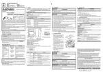
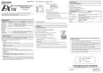
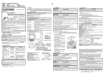
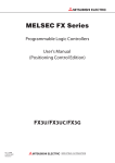
Side B JY997D33801B Side A Side B JAPANESE ENGLISH 1. Outline The FX3G-5DM display module (hereinafter called display module) is installed to the FX3G main unit to monitor/change device states and values. 1.1 Incorporated Items FX3G-5DM INSTALLATION MANUAL FX3G-5DM display module Installation Manual (This manual) 1.2 External Dimensions and Part Names [1] JY997D33801 Revision B Date September 2008 34.4(1.36") [6] This manual describes the part names, dimensions, mounting, and specifications of the product. Before use, read this manual and the manuals of all relevant products fully to acquire proficiency in handling and operating the product. Make sure to learn all the product information, safety information, and precautions. Store this manual in a safe place so that it can be taken out and read whenever necessary. Always forward it to the end user. Registration: The company and product names described in this manual are registered trademarks or the trademarks of their respective companies. Effective September 2008 Specifications are subject to change without notice. © 2008 Mitsubishi Electric Corporation Safety Precaution (Read these precautions before use.) This manual classifies the safety precautions into two categories: and . Indicates that incorrect handling may cause hazardous conditions, resulting in death or severe injury. Indicates that incorrect handling may cause hazardous conditions, resulting in medium or slight personal injury or physical damage. Depending on the circumstances, procedures indicated by also cause severe injury. It is important to follow all precautions for personal safety. may Associated Manuals Manual name FX3G Series User’s Manual - Hardware Edition Unit: mm(inches) [2] [3] Manual No. Description JY997D31301 MODEL CODE: 09R521 Explains the FX 3G Series PLC specifications for I/O, wiring, installation, and maintenance. How to obtain manuals For product manuals or documents, consult with the Mitsubishi Electric dealer from who you purchased your product. 51.2(2.02") Manual Number Product Included items [5] [4] [1] Name Caution Display module cannot attach to the top cover(S) side of a 40/60point types main unit. 2) Make sure the display module (B in the figure on the right) is in parallel with the main unit and attach it to the optional equipment connector. A 1) 9.6(0.38") Description Display Displays current time and monitored status of device. [2] "ESC" button Use to cancel operation or return to previous screen. [3] "-" button Use to move cursor or set the value. [4] "+" button Use to move cursor or set the value. [5] "OK" button Use to choose the item, set the value, etc. [6] Connector for main unit Used to connect display module to main unit. [7] Display module fixing hook Used to fix display module to main unit. 2. Installation INSTALLATION PRECAUTIONS • Make sure to cut off all phases of the power supply externally before attempting installation or wiring work. Failure to do so may cause electric shock or damage to the product. INSTALLATION PRECAUTIONS • Use the product within the generic environment specifications described in PLC main unit manual (Hardware Edition). Never use the product in areas with excessive dust, oily smoke, conductive dusts, corrosive gas (salt air, Cl 2 , H 2 S, SO 2 , or NO 2 ), flammable gas, vibration or impacts, or expose it high temperature, condensation, or rain and wind. If the product is used in such conditions, electric shock, fire, malfunctions, deterioration or damage may occur. • Do not touch the conductive parts of the product directly. Doing so may cause device failures or malfunctions. • Connect the display module securely to their designated connectors. Loose connections may cause malfunctions. The following section describes the installation method for the FX3G Series PLC (FX3G-40M . In this example). Turn off the power to the PLC before installation. For more details on installation and removal, refer to the PLC main unit manual. → Refer to the FX3G Series User's Manual - Hardware Edition 3.3 Display Specifications Item 2) Specifications Display device STN monochrome liquid crystal display Backlight Green LED backlight B Displayed letters Top cover (S) Number of letters 16 letters (half-width character) × 4 lines Character Alphabets, Numbers, Japanese character Language for menu display Button English/Japanese 4 operation buttons (OK, ESC, +, and -) 4. Function List Cut off this part when using an expansion board at the same time. 12(0.48") No. 1) Remove the top cover (A’ in the figure on the right). [7] MASS(Weight): 20g(0.05lbs) 49.4(1.95") 2.1 When Installing the Memory Cassette Directly to the Main Unit 2.2 When Using the Memory Cassette Together with an Expansion Board Assuming that the expansion board is attached to the main unit. The connector cover for the expansion board is removed. To attachment of the expansion board, refer to the following manual. → Refer to the FX3G Series User's Manual - Hardware Edition 1) Cut off the part A shown in the A right figure (display module). 2) Make sure the display module is in parallel with the main unit and 2) attach it to the optional equipment Top cover (S) B connector (B in the figure on the right). The functions of a display module are listed as follows: For details on the functions, refer to the following manuals. → Refer to the FX3G Series User's Manual - Hardware Edition • Monitor/Test • ErrorCheck • LANGUAGE • Contrast adjust • Clock setting • Keyword • Memory cassette transfer • Operation button ON/OFF information • Hexadecimal current value display setting • Display screen protect function • Specified device monitor function • Screen saver function Caution Display module cannot attach to the top cover(S) side of a 40/60point types main unit. For details on installation and removal, refer to the following manual. → Refer to the FX3G Series User's Manual - Hardware Edition 3. Specifications STARTUP AND MAINTENANCE PRECAUTIONS • Do not disassemble or modify the PLC. Doing so may cause fire, equipment failures, or malfunctions. * For repair, contact your local Mitsubishi Electric distributor. • Do not drop the product or exert strong impact to it. Doing so may cause damage. DISPOSAL PRECAUTIONS • Please contact a certified electronic waste disposal company for the environmentally safe recycling and disposal of your device. TRANSPORT AND STORAGE PRECAUTIONS • The product is a precision instrument. During transportation, avoid any impacts. Failure to do so may cause failures in the product. After transportation, verify the operations of the product. 3.1 Applicable PLC Model name FX3G Series PLC Applicability Ver.1.10 or later • Only one display module can be used per main unit. For details on the system configuration, refer to the following manual. → Refer to the FX3G Series User's Manual - Hardware Edition This manual confers no industrial property rights or any rights of any other kind, nor does it confer any patent licenses. Mitsubishi Electric Corporation cannot be held responsible for any problems involving industrial property rights which may occur as a result of using the contents noted in this manual. Warranty Mitsubishi will not be held liable for damage caused by factors found not to be the cause of Mitsubishi; opportunity loss or lost profits caused by faults in the Mitsubishi products; damage, secondary damage, accident compensation caused by special factors unpredictable by Mitsubishi; damages to products other than Mitsubishi products; and to other duties. For safe use • This product has been manufactured as a general-purpose part for general industries, and has not been designed or manufactured to be incorporated in a device or system used in purposes related to human life. • Before using the product for special purposes such as nuclear power, electric power, aerospace, medicine or passenger movement vehicles, consult with Mitsubishi Electric. • This product has been manufactured under strict quality control. However when installing the product where major accidents or losses could occur if the product fails, install appropriate backup or failsafe functions in the system. 3.2 General Specifications The general specifications are equivalent to the PLC main unit. For general specifications, refer to the following manuals. → Refer to the FX3G Series User's Manual - Hardware Edition HEAD OFFICE : TOKYO BUILDING, 2-7-3 MARUNOUCHI, CHIYODA-KU, TOKYO 100-8310, JAPAN HIMEJI WORKS : 840, CHIYODA CHO, HIMEJI, JAPAN