Transcript
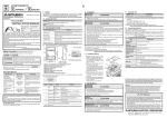
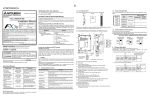
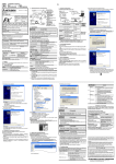
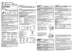
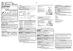
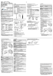
Side B JY997D32201C Side A Side B JAPANESE ENGLISH 1. Outline 2. Installation FX3G-485-BD is an expansion board equipped with an European terminal block for RS485 communication. The FX3G-485-BD exchanges data with RS-485 devices. For wiring, specifications, settings, and program examples, refer to the following manual. → Refer to the FX Series User's Manual - Data Communication Edition 1.1 Incorporated Items FX3G-485-BD INSTALLATION MANUAL Manual Number JY997D32201 Revision C Date November 2008 Effective November 2008 Specifications are subject to change without notice. © 2008 Mitsubishi Electric Corporation M3×8 tapping screws for installation: 2 pcs. Station number labels for linking Side cover Installation Manual (This manual) Communication type Function N:N network Data transfer connecting up to eight FX Series PLCs. Parallel link Data transfer between two PLCs relationship specifying master/slave station. Computer link Data transfer between PLC and computer (specified as the master station) via dedicated protocol. Non-protocol communication Serial communication between PLC and RS-485 device via non-protocol. Inverter communication*1 Controlling Mitsubishi's FREQROL inverter using Inverter communication instructions. *1 Supported in Ver. 1.10 or later [5] Depending on the circumstances, procedures indicated by also cause severe injury. It is important to follow all precautions for personal safety. may Associated Manuals [4] Description FX3G Series User’s Manual - Hardware Edition JY997D31301 MODEL CODE: 09R521 Explains the FX 3G Series PLC specifications for I/O, wiring, installation, and maintenance. FX 3 G /F X 3 U / FX 3 U C Series Programming Manual Basic & Applied Instruction Edition JY997D16601 MODEL CODE: 09R517 Describes PLC programming for basic/applied instructions and devices. JY997D16901 MODEL CODE: 09R715 Explains N:N network, Parallel Link, Computer Link, NonProtocol communication by RS and RS2 instructions/FX2N232IF. This manual describes the specifications and installation details for the FX3G485-BD. For wiring with communication equipment, system configuration, communication settings, and program examples, refer to the "FX Series User's Manual - Data Communication Edition". How to obtain manuals For product manuals or documents, consult with the Mitsubishi Electric dealer from who you purchased your product. Connector cover is removed [9] [3] [6] [2] [1] [8] MASS(Weight): 20g(0.05lbs) 35(1.38") 15.1 14.1 (0.6") (0.56") Setting terminal registor to 110Ω 110Ω Manual No. [7] 51.2(2.02") Indicates that incorrect handling may cause hazardous conditions, resulting in medium or slight personal injury or physical damage. • Make sure to cut off all phases of the power supply externally before attempting installation or wiring work. Failure to do so may cause electric shock or damage to the product. • Use the product within the generic environment specifications described in PLC main unit manual (Hardware Edition). Never use the product in areas with excessive dust, oily smoke, conductive dusts, corrosive gas (salt air, Cl2, H2S, SO2, or NO2), flammable gas, vibration or impacts, or expose it high temperature, condensation, or rain and wind. If the product is used in such conditions, electric shock, fire, malfunctions, deterioration or damage may occur. • Use screwdrivers carefully when performing installation work, thus avoiding accident or product damage. • When drilling screw holes or wiring, make sure cutting or wire debris does not enter the ventilation slits. Failure to do so may cause fire, equipment failures or malfunctions. • Do not touch the conductive parts of the product directly. Doing so may cause device failures or malfunctions. • Connect the expansion board securely to their designated connectors. Loose connections may cause malfunctions. The following section describes the installation method to the FX3G Series PLC (FX3G-40M . In this example). Turn off the power to the PLC before installation. For more details on installation and removal, refer to the PLC main unit manual. → Refer to the FX3G Series User's Manual - Hardware Edition 2.1 Installation Method . Indicates that incorrect handling may cause hazardous conditions, resulting in death or severe injury. Model name FX3G Series PLC INSTALLATION PRECAUTIONS Unit: mm(inches) This manual classifies the safety precautions into two categories: FX Series User’s Manual Data Communication Edition Included items 1.3 External Dimensions and Part Names Safety Precaution (Read these precautions before use.) Manual name RS-485 communication expansion board FX3G-485-BD 1.2 Communication Function This manual describes the part names, dimensions, mounting, and specifications of the product. Before use, read this manual and the manuals of all relevant products fully to acquire proficiency in handling and operating the product. Make sure to learn all the product information, safety information, and precautions. Store this manual in a safe place so that it can be taken out and read whenever necessary. Always forward it to the end user. Registration: The company and product names described in this manual are registered trademarks or the trademarks of their respective companies. and Product 3.1 Applicable PLC INSTALLATION PRECAUTIONS Setting no terminal registor 330Ω 110Ω Setting terminal registor to 330Ω 330Ω 110Ω 330Ω OPEN OPEN OPEN Carefully operate the switch not to damage the circuit board or electronic parts. Before changing over the switch, remove the upper side of the removable terminal. → For details, refer to the FX Series User's Manual-Data Communication Edition [1]Terminal resistor changing-over switch (110Ω/OPEN/330Ω) [2]Terminal block mounting screws [3]SD LED: Lighting while sending data [4]Mounting holes(2-φ3.2) [5]Connector cover [6]RD LED: Lighting while receiving data [7]Main unit connector [8]Terminal block to connect RS-485 device (European terminal block) [9]Memory cassette/Display module connector Recommended screwdriver to tighten terminal screws The end should be straight 0.4mm (0.01") 2.5mm (0.09") 1) Remove the top cover (A in the figure on the right) or top cover (S) (A’ in the figure on the right). In a 14/24-point type main unit, only the top cover (A in the figure on the right) is provided. 2) Attach the accessory side cover (B in the figure on the right). It is not necessary to attach the side cover (B in the figure on the right) when installing the FX3G-485-BD to only under the top cover (S) of a 40/ 60-point type main unit. 3) Make sure the expansion board is in parallel with the main unit and attach it to the optional equipment connector. 4) Fix the expansion board to the main unit using the provided M3 tapping screws. (2 places) Tightening torque : 0.3 to 0.6 N⋅m A A' • The number of connectable expansion boards varies depending on the main unit as follows: FX3G-14M , 24M Main units : 1 unit FX3G-40M , 60M Main units : 2 units Never stack up two or more expansion boards. For details on the system configuration, refer to the following manual. → Refer to the FX Series User's Manual - Data Communication Edition 3.2 General Specifications The general specifications are equivalent to the PLC main unit. For general specifications, refer to the following manuals. However, since the product is not isolated between communication lines and the CPU of main unit, please do not perform any dielectric withstand voltage tests or insulation resistance tests to this product. → Refer to the FX3G Series User's Manual - Hardware Edition 3.3 Communication specifications Item Transmission standard 3) B 3) European terminal block Indication (LED) RD, SD Communication method Half-duplex Communication format Non-Protocol Communication, Computer Link (dedicated protocol format 1 and 4), Parallel Link, N:N network, and Inverter communication*1 Baud rate Non-Protocol Communication, Computer Link : 300/600/1200/2400/4800/9600/19200 /38400 bps Parallel Link : 115200 bps N:N network : 38400 bps Inverter communication*1 : 4800/9600/19200/38400 bps Insulation Not insulated (Between communication line and CPU) 2) 3. Specifications STARTUP AND MAINTENANCE PRECAUTIONS • Do not disassemble or modify the PLC. Doing so may cause fire, equipment failures, or malfunctions. * For repair, contact your local Mitsubishi Electric distributor. • Do not drop the product or exert strong impact to it. Doing so may cause damage. DISPOSAL PRECAUTIONS • Please contact a certified electronic waste disposal company for the environmentally safe recycling and disposal of your device. TRANSPORT AND STORAGE PRECAUTIONS In conformance to RS-485/RS-422 Connection method 1) 4) Specification Maximum 50m (164ft) maximum transmission distance 1) 4) Applicability Ver.1.00 or later (from first production) *1 Supported in Ver. 1.10 or later This manual confers no industrial property rights or any rights of any other kind, nor does it confer any patent licenses. Mitsubishi Electric Corporation cannot be held responsible for any problems involving industrial property rights which may occur as a result of using the contents noted in this manual. Warranty Mitsubishi will not be held liable for damage caused by factors found not to be the cause of Mitsubishi; opportunity loss or lost profits caused by faults in the Mitsubishi products; damage, secondary damage, accident compensation caused by special factors unpredictable by Mitsubishi; damages to products other than Mitsubishi products; and to other duties. For safe use • This product has been manufactured as a general-purpose part for general industries, and has not been designed or manufactured to be incorporated in a device or system used in purposes related to human life. • Before using the product for special purposes such as nuclear power, electric power, aerospace, medicine or passenger movement vehicles, consult with Mitsubishi Electric. • This product has been manufactured under strict quality control. However when installing the product where major accidents or losses could occur if the product fails, install appropriate backup or failsafe functions in the system. • The product is a precision instrument. During transportation, avoid any impacts. Failure to do so may cause failures in the product. After transportation, verify the operations of the product. HEAD OFFICE : TOKYO BUILDING, 2-7-3 MARUNOUCHI, CHIYODA-KU, TOKYO 100-8310, JAPAN HIMEJI WORKS : 840, CHIYODA CHO, HIMEJI, JAPAN