1
Wind Power Inverter
WINDY BOY 3600TL / 5000TL
Installation Guide
WB36TL_50TL-IEN102011 | IMEN-WB36_50TL | Version 1.1
EN
SMA Solar Technology AG
Table of Contents
Table of Contents
1
1.1
1.2
1.3
1.4
Notes on this Manual. . . . . . . . . . . . . . . . . . . . . . . . . . . . . .
Validity . . . . . . . . . . . . . . . . . . . . . . . . . . . . . . . . . . . . . . . . . . . .
Target Group . . . . . . . . . . . . . . . . . . . . . . . . . . . . . . . . . . . . . . .
Additional Information . . . . . . . . . . . . . . . . . . . . . . . . . . . . . . . .
Symbols Used . . . . . . . . . . . . . . . . . . . . . . . . . . . . . . . . . . . . . . .
2
2.1
2.2
2.3
Safety . . . . . . . . . . . . . . . . . . . . . . . . . . . . . . . . . . . . . . . . . . 9
Appropriate Usage . . . . . . . . . . . . . . . . . . . . . . . . . . . . . . . . . . . 9
Safety Precautions. . . . . . . . . . . . . . . . . . . . . . . . . . . . . . . . . . . 10
Explanation of Symbols . . . . . . . . . . . . . . . . . . . . . . . . . . . . . . 11
2.3.1
Symbols on the Inverter. . . . . . . . . . . . . . . . . . . . . . . . . . . . . . . . . . . . . . . . . 11
2.3.2
Symbols on the Type Plate . . . . . . . . . . . . . . . . . . . . . . . . . . . . . . . . . . . . . . 12
3
3.1
3.2
Unpacking. . . . . . . . . . . . . . . . . . . . . . . . . . . . . . . . . . . . . . 13
Packing List . . . . . . . . . . . . . . . . . . . . . . . . . . . . . . . . . . . . . . . . 13
Identifying the Inverter . . . . . . . . . . . . . . . . . . . . . . . . . . . . . . . 13
4
4.1
4.2
4.3
4.4
Mounting. . . . . . . . . . . . . . . . . . . . . . . . . . . . . . . . . . . . . . . 14
Safety . . . . . . . . . . . . . . . . . . . . . . . . . . . . . . . . . . . . . . . . . . . . 14
Selecting the Mounting Location. . . . . . . . . . . . . . . . . . . . . . . . 15
Mounting the Inverter with the Wall Mounting Bracket . . . . . . 17
Mounting the inverter with a top hat rail. . . . . . . . . . . . . . . . . . 21
5
5.1
5.2
5.3
Electrical Connection . . . . . . . . . . . . . . . . . . . . . . . . . . . . . 24
Safety . . . . . . . . . . . . . . . . . . . . . . . . . . . . . . . . . . . . . . . . . . . . 24
Overview of the Connection Area . . . . . . . . . . . . . . . . . . . . . . 24
Connection to the Power Distribution Grid (AC). . . . . . . . . . . . 26
5.3.1
5.3.2
Conditions for the AC Connection . . . . . . . . . . . . . . . . . . . . . . . . . . . . . . . . 26
Connecting the Inverter to the Power Distribution Grid (AC) . . . . . . . . . . . . 29
5.3.3
Additional Grounding of the Housing. . . . . . . . . . . . . . . . . . . . . . . . . . . . . . 32
Installation Guide
WB36TL_50TL-IEN102011
7
7
7
7
8
3
Table of Contents
SMA Solar Technology AG
5.4
Connecting Windy Boy Protection Box (DC) . . . . . . . . . . . . . . 33
5.4.1
Conditions for the DC Connection . . . . . . . . . . . . . . . . . . . . . . . . . . . . . . . . 33
5.4.2
Assembling the DC Plug Connector . . . . . . . . . . . . . . . . . . . . . . . . . . . . . . . 34
5.4.3
Opening the DC Plug Connector . . . . . . . . . . . . . . . . . . . . . . . . . . . . . . . . . 36
5.4.4
Connecting the Windy Boy Protection Box (DC) . . . . . . . . . . . . . . . . . . . . . 37
5.5
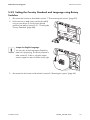
Setting the Country Standard and Display Language . . . . . . . 39
5.5.1
Checking the Country Standard . . . . . . . . . . . . . . . . . . . . . . . . . . . . . . . . . . 40
5.5.2
Setting the Country Standard and Language using Rotary Switches . . . . . . 43
5.6
Communication. . . . . . . . . . . . . . . . . . . . . . . . . . . . . . . . . . . . . 44
5.6.1
Multi-function relay . . . . . . . . . . . . . . . . . . . . . . . . . . . . . . . . . . . . . . . . . . . . 45
5.6.2
Communication module . . . . . . . . . . . . . . . . . . . . . . . . . . . . . . . . . . . . . . . . 48
5.6.3
Polynomial Characteristic Curve . . . . . . . . . . . . . . . . . . . . . . . . . . . . . . . . . . 49
6
6.1
Initial start-up . . . . . . . . . . . . . . . . . . . . . . . . . . . . . . . . . . . 50
Self-test according to DK 5940, ED. 2.2 (for Italy only). . . . . . 52
6.1.1
Starting the Self-Test by Tapping . . . . . . . . . . . . . . . . . . . . . . . . . . . . . . . . . . 52
6.1.2
6.1.3
Test Sequence . . . . . . . . . . . . . . . . . . . . . . . . . . . . . . . . . . . . . . . . . . . . . . . . 53
Interruption of the Self-Test . . . . . . . . . . . . . . . . . . . . . . . . . . . . . . . . . . . . . . 56
6.1.4
Restarting the Self-Test. . . . . . . . . . . . . . . . . . . . . . . . . . . . . . . . . . . . . . . . . . 57
6.2
6.3
Display Messages during Initialization . . . . . . . . . . . . . . . . . . . 57
Operating Conditions of the Inverter . . . . . . . . . . . . . . . . . . . . 58
7
7.1
7.2
Disconnecting the Inverter. . . . . . . . . . . . . . . . . . . . . . . . . 59
Safety . . . . . . . . . . . . . . . . . . . . . . . . . . . . . . . . . . . . . . . . . . . . 59
Disconnect the device from voltage sources . . . . . . . . . . . . . . . 59
8
Restarting the system . . . . . . . . . . . . . . . . . . . . . . . . . . . . . 62
9
9.1
Maintenance and Cleaning . . . . . . . . . . . . . . . . . . . . . . . . 65
Checking Heat Dissipation . . . . . . . . . . . . . . . . . . . . . . . . . . . . 65
9.1.1
9.1.2
Cleaning the Fan. . . . . . . . . . . . . . . . . . . . . . . . . . . . . . . . . . . . . . . . . . . . . . 65
Checking the Fans. . . . . . . . . . . . . . . . . . . . . . . . . . . . . . . . . . . . . . . . . . . . . 67
9.2
Checking the Electronic Solar Switch (ESS) for Wear . . . . . . . 68
4
WB36TL_50TL-IEN102011
Installation Guide
SMA Solar Technology AG
Table of Contents
10
Slot for SD card . . . . . . . . . . . . . . . . . . . . . . . . . . . . . . . . . 69
11
11.1
11.2
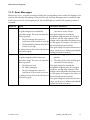
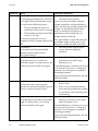
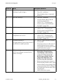
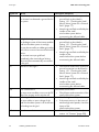
Messages . . . . . . . . . . . . . . . . . . . . . . . . . . . . . . . . . . . . . . 70
Event messages. . . . . . . . . . . . . . . . . . . . . . . . . . . . . . . . . . . . . 70
Error Messages. . . . . . . . . . . . . . . . . . . . . . . . . . . . . . . . . . . . . 71
12
12.1
12.2
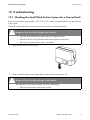
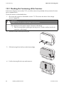
Troubleshooting . . . . . . . . . . . . . . . . . . . . . . . . . . . . . . . . . 77
Checking the Small Wind Turbine System for a Ground Fault . 77
Checking the Functioning of the Varistors . . . . . . . . . . . . . . . . . 80
13
13.1
13.2
13.3
13.4
Decommissioning . . . . . . . . . . . . . . . . . . . . . . . . . . . . . . . . 84
Dismantling the Inverter. . . . . . . . . . . . . . . . . . . . . . . . . . . . . . . 84
Packing the Inverter. . . . . . . . . . . . . . . . . . . . . . . . . . . . . . . . . . 84
Storing the Inverter . . . . . . . . . . . . . . . . . . . . . . . . . . . . . . . . . . 84
Disposing of the Inverter . . . . . . . . . . . . . . . . . . . . . . . . . . . . . . 84
14
14.1
14.2
Technical Data . . . . . . . . . . . . . . . . . . . . . . . . . . . . . . . . . . 85
Windy Boy 3600TL . . . . . . . . . . . . . . . . . . . . . . . . . . . . . . . . . 85
Windy Boy 5000TL . . . . . . . . . . . . . . . . . . . . . . . . . . . . . . . . . 88
15
Accessories . . . . . . . . . . . . . . . . . . . . . . . . . . . . . . . . . . . . . 91
16
Contact . . . . . . . . . . . . . . . . . . . . . . . . . . . . . . . . . . . . . . . . 92
Installation Guide
WB36TL_50TL-IEN102011
5
Table of Contents
6
WB36TL_50TL-IEN102011
SMA Solar Technology AG
Installation Guide
SMA Solar Technology AG
Notes on this Manual
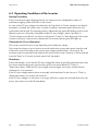
1 Notes on this Manual
This manual describes the assembly, installation, commissioning and maintenance of the following
SMA inverters:
• Windy Boy 3600TL (WB 3600TL-20)
• Windy Boy 5000TL (WB 5000TL-20)
Store this manual where it can be accessed at all times.
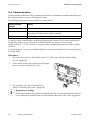
1.1 Validity
This manual is valid for the Windy Boy 3600TL and Windy Boy 5000TL.
1.2 Target Group
This manual is for qualified personnel. The tasks described in this manual may be performed by
qualified electrical technicians only.
1.3 Additional Information
You will find further information on special topics such as designing a line circuit breaker or the
description of the operating parameters in the download area at www.SMA.de/en.
Refer to the user manual for detailed information on operating the inverter.
Installation Guide
WB36TL_50TL-IEN102011
7
Notes on this Manual
SMA Solar Technology AG
1.4 Symbols Used
The following types of safety warnings and general information are used in this manual:
DANGER!
"DANGER" indicates a hazardous situation which, if not avoided, will result in death or
serious injury.
WARNING!
"WARNING" indicates a hazardous situation which, if not avoided, could result in death
or serious injury.
CAUTION!
"CAUTION" indicates a hazardous situation which, if not avoided, could result in minor or
moderate injury.
NOTICE!
"NOTICE" indicates a situation that can result in property damage if not avoided.
Information
Information provides tips that are valuable for the optimal installation and operation of
your product.
☑
8
This symbol indicates the result of an action.
WB36TL_50TL-IEN102011
Installation Guide
SMA Solar Technology AG
Safety
2 Safety
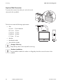
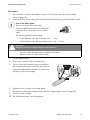
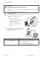
2.1 Appropriate Usage
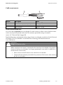
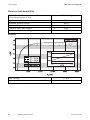
The Windy Boy is a wind power inverter, which converts rectified current of a small wind turbine system
into AC current and feeds this energy into the power distribution grid, domestic grid or the
Sunny Island system.
Principle of a small wind turbine system with Windy Boy
Furthermore, the Windy Boy can be used as an inverter for power conversion units based on the
permanent magnet generators (hydro power systems, combined heat and power plant,
diesel generator, etc.). The manufacturer of the small wind turbine system or the generators should
have his system set up for operation with the Windy Boy (see also the Windy Boy planning guidelines
in the download area at www.SMA.de/en).
SMA Solar Technology AG recommends to operate Windy Boy and a small wind turbine system
without neutral grounding.
When designing the system, ensure that the permitted operating range of all components is
maintained at all times. Also use appropriate protective measures to make sure that the maximum
permissible input voltage of the inverter is not exceeded. Use of the WBP-Box 500-11
Windy Boy Protection Box by SMA Solar Technology AG is obligatory.
Do not use the Windy Boy for purposes other than those described here. Alternative uses,
modifications to the Windy Boy or the installation of components not expressly recommended or sold
by SMA Solar Technology AG void the warranty claims and operation permission.
Installation Guide
WB36TL_50TL-IEN102011
9
Safety
SMA Solar Technology AG
2.2 Safety Precautions
DANGER!
Danger to life due to high voltages in the inverter.
• All work on the inverter may be carried out by qualified personnel only.
• The appliance is not to be used by children or persons with reduced physical, sensory
or mental capabilities, or lack of experience and knowledge, unless they have been
given supervision or instruction.
• Children should be supervised to ensure that they do not play with the appliance.
CAUTION!
Danger of burn injuries due to hot enclosure parts.
During operation, the upper lid of the enclosure and the enclosure body may become hot.
• Only touch the lower enclosure lid during operation.
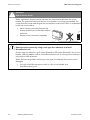
CAUTION!
Possible damage to health as a result of the effects of radiation.
• Do not stay closer than 20 cm to the inverter for any length of time.
10
WB36TL_50TL-IEN102011
Installation Guide
SMA Solar Technology AG
Safety
2.3 Explanation of Symbols
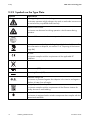
This section contains an explanation of all symbols found on the inverter and type label.
2.3.1 Symbols on the Inverter
Symbol
Explanation
Operation Display. Indicates the operation condition of the inverter.
An error has occurred. Read the installation guide and the user manual
to remedy the malfunction.
Bluetooth® Wireless Technology. Shows the status of Bluetooth
communication.
Tap to switch on the display light and switch to the next display message.
When the Electronic Solar Switch is plugged in, the DC circuit is closed.
To interrupt the DC circuit and disconnect the inverter securely under
load
, you must release the inverter as described in
section 7.2 ”Disconnect the device from voltage sources” (page 59).
Installation Guide
WB36TL_50TL-IEN102011
11
Safety
SMA Solar Technology AG
2.3.2 Symbols on the Type Plate
Symbol
Explanation
Warning: dangerous electrical voltage.
The inverter operates at high voltages. Any work on and at the inverter must
be carried out by a qualified electrician only.
Beware of hot surface.
The inverter can become hot during operation. Avoid contact during
operation.
Observe all documentation that accompanies the inverter.
The inverter must not be disposed of together with the household waste. For
more information on disposal, see section 13.4 ”Disposing of the Inverter”
(page 84).
CE mark.
The inverter complies with the requirements of the applicable EC
guidelines.
The inverter is transformerless.
Direct current (DC).
Alternating Current (AC).
Protection rating IP54.
The inverter is protected against dust deposits in the interior and against
splashes of water from all angles.
RAL quality mark for solar products.
The inverter complies with the requirements of the German Institute for
Quality Assurance and Labeling.
Device class label.
The inverter is equipped with a wireless component that complies with the
harmonized standards.
12
WB36TL_50TL-IEN102011
Installation Guide
SMA Solar Technology AG
Unpacking
3 Unpacking
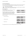
3.1 Packing List
Check the delivery for completeness and any visible external damage. Contact your dealer if anything
is damaged or missing.
Object
A
B
C
D
E
F
G
H
Number
1
1
8
8
1
1
1
1
Description
Inverter
Wall mounting bracket
DC plug connectors (4 x positive / 4 x negative)
Sealing plugs for DC plug connectors
Installation Guide
User Manual
Set of documents with explanations and certificates
Supplementary sheet with inverter factory settings
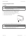
3.2 Identifying the Inverter
You can identify the inverter by the type plate. The type plate is on the right side of the enclosure.
The serial number (Serial No.) and the type (Type / Model) of the product, as well as device-specific
characteristics are specified on the type plate.
Installation Guide
WB36TL_50TL-IEN102011
13
Mounting
SMA Solar Technology AG
4 Mounting
4.1 Safety
DANGER!
Danger to life due to fire or explosion.
Despite careful construction, electrical devices can cause fires.
• Do not mount the inverter on flammable construction materials.
• Do not mount the inverter in areas where highly flammable materials are stored.
• Do not mount the inverter in areas with a risk of explosion.
CAUTION!
Danger of burn injuries due to hot enclosure parts.
• Mount the inverter in such a way that it cannot be touched inadvertently during
operation.
CAUTION!
Risk of injury due to the heavy weight of the inverter.
• Remember that the inverter weighs approx. 18 kg.
14
WB36TL_50TL-IEN102011
Installation Guide
SMA Solar Technology AG
Mounting
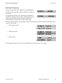
4.2 Selecting the Mounting Location
Consider the following points when selecting where to install:
• The mounting method and location must be suitable for the inverter's weight and dimensions
(see section 14 ”Technical Data” (page 85)).
• Mount on a solid surface.
• The mounting location must at all times be clear and have safe access without the use of
additional aids such as scaffolding or lifting platforms. Any possible service actions are
otherwise limited.
• Vertical installation or tilted backwards by max. 15°.
• Never mount the device with a forward tilt.
• Do not mount horizontally.
• The connection area must point downward.
• Mount at eye level to allow operating status to be read at all times.
• To ensure optimal operation, the ambient temperature should be below 40 °C.
• Do not expose the inverter to direct sunlight to avoid a power reduction due to excessive
heating.
• In a living area, do not mount the unit on plasterboard walls (or similar) in order to avoid audible
vibrations. The inverter can make noises when in use, which may be perceived as a nuisance in
a living area.
Installation Guide
WB36TL_50TL-IEN102011
15
Mounting
SMA Solar Technology AG
• Observe the minimum clearances to walls, other
inverters or objects as shown in the diagram in
order to ensure sufficient heat dissipation and
sufficient space for the removal of the Electronic
Solar Switch.
Multiple inverters installed in areas with high ambient temperatures
There must be sufficient clearance between the individual inverters to ensure that inverters
are not subjected to dissipated air from adjacent devices.
If necessary, increase the clearances and make sure there is enough ventilation to ensure
sufficient cooling of the inverters.
16
WB36TL_50TL-IEN102011
Installation Guide
SMA Solar Technology AG
Mounting
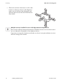
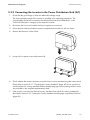
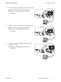
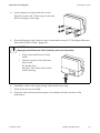
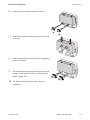
4.3 Mounting the Inverter with the Wall Mounting Bracket
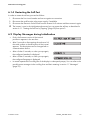
1. Use the wall mounting bracket as a drilling template and mark the positions of the drill holes.
Number of drill holes used
• When mounting on the wall, use one of the top holes on the left and right and the
bottom hole in the center.
• Use the two holes in the center when mounting the device to a pillar.
Installation Guide
WB36TL_50TL-IEN102011
17
Mounting
SMA Solar Technology AG
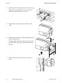
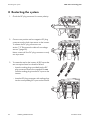
2. Attach the wall mounting bracket to the wall using
appropriate screws (diameter min. 6 mm) and
washers (outer diameter min. 18 mm).
3. Transport the inverter using the handles on the
sides.
4. Attach the inverter to the wall bracket slightly to the
left of its final position.
The right edge of the rear side of the inverter must
be flush with the right edge of the wall mounting
bracket.
5. Check both sides to ensure that it is correctly in
place.
18
WB36TL_50TL-IEN102011
Installation Guide
SMA Solar Technology AG
Mounting
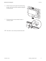
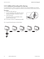
6. Push the inverter to the right on the wall mounting
bracket, until it locks into place with the locking bolt
on the back wall.
7. Check both sides to ensure that the inverter is
correctly in place.
☑ The inverter is now securely mounted to the wall.
Installation Guide
WB36TL_50TL-IEN102011
19
Mounting
SMA Solar Technology AG
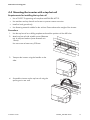
Optional Theft Protection
To protect the inverter from theft, you can lock it to the
rear panel with a padlock.
The lock must meet the following requirements:
• Size:
A: 6 mm … 10 mm diameter
B: 21 mm … 35 mm
C: 20 mm … 33 mm
D: 40 mm … 60 mm
E: 13 mm … 21 mm
• Stainless
• Hardened shackle
• Secured lock cylinder
Storage of the key
Keep the key safe in case required for servicing.
Outdoor Installation
Use a padlook suitable for outdoor use. Regularly check the correct function of the
padlock.
20
WB36TL_50TL-IEN102011
Installation Guide
SMA Solar Technology AG
Mounting
4.4 Mounting the inverter with a top hat rail
Requirements for installing the top hat rail
• Use a TH-35-7.5 supporting rail compliant with DIN EN 60715.
• Use stainless steel top hat rail and screws to prevent contact corrosion.
• Install on level ground only.
• Use fastening material suitable for the surface. Please observe the weight of the inverter.
Procedure
1. Use the top hat rail as a drilling template and mark the positions of the drill holes.
2. Attach top hat rail with suitable screws (diameter
min. 6 mm) and washers (outer diameter min.
18 mm).
Use one screw at least every 300 mm.
3. Transport the inverter using the handles on the
sides.
4. Suspend the inverter on the top hat rail using the
opening on its rear wall.
Installation Guide
WB36TL_50TL-IEN102011
21
Mounting
SMA Solar Technology AG
5. Check both sides to ensure that it is correctly in
place.
Securing the Inverter Against Excavation
Additionally secure the inverter in the wall using screws.
1. Remove the Electronic Solar Switch towards the bottom.
2. Loosen all six captive screws and remove lid.
3. Drill through the back wall of the enclosure.
4. Use a suitable drill bit at least 120 mm in length.
5. Insert suitable wall anchor.
22
WB36TL_50TL-IEN102011
Installation Guide
SMA Solar Technology AG
Mounting
6. Fasten the inverter.
The screw must meet the following requirements:
Length:
Diameter:
Screw head:
min. 100 mm
8 mm
Hex screws or slotted screws
not countersunk
☑ The inverter is protected against excavation.
Installation Guide
WB36TL_50TL-IEN102011
23
Electrical Connection
SMA Solar Technology AG
5 Electrical Connection
5.1 Safety
WARNING!
Electric shock resulting from short circuit.
If cables with a different voltage are routed in parallel, there is the risk of a short circuit in
the event of damage to the cable insulation.
• Route all cables separately.
CAUTION!
Electrostatic discharges can damage the inverter.
Internal components of the inverter can be irreparably damaged by static discharge.
• Ground yourself before touching a component.
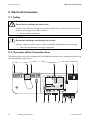
5.2 Overview of the Connection Area
The following figure shows the assignment of the individual connection areas, openings in the housing
and cable glands of the inverter.
24
WB36TL_50TL-IEN102011
Installation Guide
SMA Solar Technology AG
Electrical Connection
Object
A
Description
Input area A:
B
C
DC plug connectors to connect Windy Boy Protection Box (WBP‑Box 500-11)
Electronic Solar Switch (ESS) socket
Input area B:
D
E
F
G
H
I
K
L
M
N
O
DC plug connectors to connect Windy Boy Protection Box (WBP‑Box 500-11)
Connector for optional communication via RS485
Terminal for multi-function relay
Terminals for grid connection (AC)
Cable gland for grid connection (AC) (12 mm … 25 mm)
Cable gland for connection to multi-function relay (6 mm … 12 mm)
Jumper slot for setting the language to English
Rotary switch for the configuration of Bluetooth communication
Housing opening for optional communication via RS485
Rotary switch to set the country of installation and the display language
Slot for the SD card
Ground terminal to additionally ground the inverter
Installation Guide
WB36TL_50TL-IEN102011
25
Electrical Connection
SMA Solar Technology AG
5.3 Connection to the Power Distribution Grid (AC)
5.3.1 Conditions for the AC Connection
Observe all connection conditions of the utility operator for connecting to the power distribution grid!
Residual current breaker
The inverter is equipped with an integrated universal current sensitive residual-current monitoring unit.
The inverter can automatically differ between real fault currents and "normal" capacitive leakage
currents.
If an external RCD or residual current breaker is strictly required, you must use a switch that triggers
at a failure current of 100 mA or higher.
Cable Sizing
The grid impedance of the AC cable must not exceed 1 Ohm. Otherwise, the inverter will disconnect
at full feed capacity due to excessive voltage at the feed-in point.
The wire cross-section should be dimensioned so output losses do not exceed 1 % at nominal power.
The maximum cable lengths depending on the wire diameter are displayed in the following table.
Cross section of insulated
conductor
6.0 mm²
10.0 mm²
Maximum wire length
WB 3600TL
WB 5000TL
23.3 m
18.6 m
38.8 m
31.1 m
The conductor cross-sectional area required in individual cases depends on the following factors,
among others:
• Ambient temperature,
• Routing method,
• UV resistance,
• Conduction losses,
• valid installation requirements of the respective country (installation location).
26
WB36TL_50TL-IEN102011
Installation Guide
SMA Solar Technology AG
Electrical Connection
Cable requirements
Object
A
B
C
Description
External diameter
Cross section of insulated conductor
Strip insulation
value
12 mm … 25 mm
max. 10 mm²
Approx. 12 mm
Load Disconnection Unit
You must install a separate line circuit breaker for each inverter in order to ensure that the inverter
can be securely disconnected under load. The maximum permissible rating is located in
section 14 ”Technical Data” (page 85).
Detailed information and examples for the rating of a line circuit breaker can be found in the Technical
Information "Line Circuit Breaker" in the SMA Solar Technology AG download area at
www.SMA.de/en.
DANGER!
Danger to life due to fire.
When more than one inverter is connected to the same line circuit breaker, the protective
function of the line circuit breaker is no longer guaranteed. It can result in a cable fire or
the destruction of the inverter.
• Never connect several inverters to the same line circuit breaker.
• Comply with the maximum permissible fuse protection of the inverter when selecting
the line circuit breaker.
Installation Guide
WB36TL_50TL-IEN102011
27
Electrical Connection
SMA Solar Technology AG
DANGER!
Risk of electric shock.
When a generator (inverter) and a consumer are connected to the same line circuit
breaker, the protective function of the line circuit breaker is no longer guaranteed. The
current from the inverter and the grid can accumulate to overcurrent, which is not detected
by the line circuit breaker.
• Never connect consumers between the
inverter and the line circuit breaker without
protection.
• Always protect consumers separately.
CAUTION!
Damage to the inverter by using screw type fuse elements as a load
disconnection unit.
A screw type fuse element, e.g. D system (Diazed) or D0 system (Neozed) is not a circuit
breaker, and may not be used as a load disconnection unit. A screw type fuse element is
only used as cable protection.
When disconnecting under load using a screw type fuse element, the inverter can be
damaged.
• Use only a load disconnection switch or a line circuit breaker as a
load disconnecting unit.
28
WB36TL_50TL-IEN102011
Installation Guide
SMA Solar Technology AG
Electrical Connection
5.3.2 Connecting the Inverter to the Power Distribution Grid (AC)
1. Check that the grid voltage is within the admissible voltage range.
The exact operating range of the inverter is specified in the operating parameters. The
corresponding document is located in the download area at www.SMA.de/en, in the
"Technical Description" category of the respective inverter.
2. Disconnect the line circuit breaker and secure against re-connection.
3. Ensure that the small wind turbine system is stopped and secured so it will not restart.
4. Remove the Electronic Solar Switch.
5. Loosen all six captive screws and remove lid.
6. Check whether the inverter has been set to the correct country standard using the rotary switch.
Please refer to section 5.5.1 ”Checking the Country Standard” (page 40) for an overview of
switch positions for country standards and the display language. Factory settings of the inverter
are provided on the supplied supplementary sheet.
7. If the inverter is not set to the desired country standard, then adjust the country standard as
described in section 5.5.2 ”Setting the Country Standard and Language using Rotary Switches”
(page 43).
Installation Guide
WB36TL_50TL-IEN102011
29
Electrical Connection
SMA Solar Technology AG
8. Loosen the screw if the display until it can be flipped
upward to facilitate connection.
Flip up the display until it clicks into place.
9. Undo the lock not of the AC cable gland and
remove the filler plug from the cable gland.
Seal in the AC cable gland
There is a two-part seal in the cable gland.
Remove the inner insert of the seal if required.
This is necessary to route a thicker cable.
The following guideline values apply:
• Cable diameter with seal and insert: 12 mm … 16 mm
• Cable diameter with seal without insert: 15 mm … 21 mm
10. Pull the cable through.
11. Open all AC terminals.
CAUTION!
Risk of fire when connecting two wires to one terminal.
If 2 wires are connected to one terminal, a poor electrical contact can result in overheating
or a risk of fire.
• Never connect more than one conductor per terminal.
30
WB36TL_50TL-IEN102011
Installation Guide
SMA Solar Technology AG
Electrical Connection
12. Connect L, N and protective conductor (PE) to the
AC terminal in accordance with the labels.
To do this, the insulated PE conductor must be 5 mm
longer than the insulated L and N conductors!
L and N must not be swapped.
CAUTION!
Danger of crushing when terminals snap shut.
The terminals close by snapping down fast and hard.
• Press the terminals down with your thumb, do not grip the entire terminal on all sides.
• Keep fingers away from the terminals.
13. Close all terminals of the AC terminal again until they snap into place.
14. Fold display down again and screw in place.
15. Tighten the lock nut firmly to the cable gland.
DANGER!
Danger to life due to high voltages in the inverter.
• Do not switch on the line circuit breaker until the small wind turbine system has been
connected and the inverter is securely closed.
☑ The inverter is now connected to the power distribution grid (AC).
Installation Guide
WB36TL_50TL-IEN102011
31
Electrical Connection
SMA Solar Technology AG
5.3.3 Additional Grounding of the Housing
If a second protective conductor connection is required in the country of installation, you can also
ground the inverter using a second protective conductor on the connection terminal on the enclosure.
Procedure
1. Undo screw (A) by half way.
2. Insert the stripped grounding cable (D) under the
clamping clip (C) (max. cross-section 16 mm²).
3. Fasten terminal (C).
The toothing of the lock washer (B) must face
toward the terminal clamp.
☑ The inverter's enclosure is additionally grounded.
You can ground several inverters as shown below:
32
WB36TL_50TL-IEN102011
Installation Guide
SMA Solar Technology AG
Electrical Connection
5.4 Connecting Windy Boy Protection Box (DC)
5.4.1 Conditions for the DC Connection
CAUTION!
Destruction of the inverter by overvoltage.
If the voltage of the small wind turbine system exceeds the maximum input voltage of the
inverter, it can be destroyed by the overvoltage. All warranty claims become void.
• Exclusively connect a type "WBP-Box 500-11" Windy Boy Protection Box to the
inverter.
• The following limit values at the DC input of the inverter may not be exceeded:
maximum input voltage
550 V
Maximum input current
Input area A
Input area B
15 A
15 A
• Connection cables of the Windy Boy Protection Box must be equipped with plug connectors to
connect them to the inverter. The required DC plug connectors are included in delivery.
DANGER!
Risk of lethal electric shock or fire.
The maximum possible input current is limited by the plug connectors used. If the plug
connector is overloaded, an electric arc may occur and there is a fire risk.
• Ensure that the input current does not exceed the maximum flow current of the plug
connectors used.
• The inverter has two input areas "A" and "B" that work with one working point. Connect one
positive terminal and one negative terminal to each of the two input areas of the
Windy Boy Protection Box (WBP-Box 500-11). See section 5.4.4 ”Connecting the Windy Boy
Protection Box (DC)” (page 37).
• This inverter is not suitable for connection to the DC power grid.
• Do not connect the inverter to a DC source with a cable longer than 30 m.
Installation Guide
WB36TL_50TL-IEN102011
33
Electrical Connection
SMA Solar Technology AG
5.4.2 Assembling the DC Plug Connector
Connection cables of the Windy Boy Protection Box (WBP-Box 500-11) must be equipped the
included with DC plug connectors to connect them to the inverter.
To assemble the DC plug connectors, proceed as detailed below. Ensure the plug connectors have
the correct polarity. The DC plug connectors have the symbols "+" and " − ".
Cable requirements:
• Use a PV1-F cable.
Procedure
1. Insert stripped cable into the plug up to the limit.
2. Press the clamping clip down until it audibly snaps
into place.
3. Ensure the cable is correctly in place:
Result
☑ If the conductors are visible in the hollow
cavity of the clamping clip, the cable is in
the correct position.
34
WB36TL_50TL-IEN102011
Action
• Proceed to step 4.
Installation Guide
SMA Solar Technology AG
Electrical Connection
Result
Action
☑ If the conductor is not visible in the hollow • Loosen the clamping clip using a
cavity, the cable is not in the correct
screwdriver.
position.
• Remove cable and start again from step 1.
4. Push the threaded joint to the thread and screw into place.
☑ The DC plug connectors are now assembled and can be connected to the inverters, as
described in section 5.4.4 ”Connecting the Windy Boy Protection Box (DC)” (page 37).
Installation Guide
WB36TL_50TL-IEN102011
35
Electrical Connection
SMA Solar Technology AG
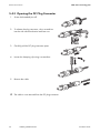
5.4.3 Opening the DC Plug Connector
1. Screw the threaded joint off.
2. To release the plug connector, slot a screwdriver
into the side catch mechanism and lever out.
3. Carefully pull the DC plug connector apart.
4. Loosen the clamping clip using a screwdriver.
5. Remove the cable.
☑ The cable is now removed from the DC plug connector.
36
WB36TL_50TL-IEN102011
Installation Guide
SMA Solar Technology AG
Electrical Connection
5.4.4 Connecting the Windy Boy Protection Box (DC)
DANGER!
Danger to life due to high voltages in the inverter.
• Before connecting the Windy Boy Protection Box (WBP-Box 500-11), ensure that the
small wind turbine system connected to the Windy Boy Protection Box has been
stopped and secured against restart.
1. Check the DC plug connectors for correct polarity.
2. Connect one positive and one negative DC plug
connector each to both input areas of the inverter.
To release the DC plug connectors see
section 7.2 ”Disconnect the device from voltage
sources” (page 59).
Never connect all 4 DC plug connectors to only
one input area!
Installation Guide
WB36TL_50TL-IEN102011
37
Electrical Connection
SMA Solar Technology AG
3. To create the seal on the inverter, all DC inputs that
are not required must be closed as follows:
– Insert the sealing plugs provided into the
DC plug connectors that are not needed.
Do not insert the blank plugs into the DC inputs
on the inverter.
– Insert the DC plug connectors with sealing plugs
into the corresponding DC inputs on the inverter.
☑ Windy Boy Protection Box has been connected.
You can now commission the inverter as described
in section 6 ”Initial start-up” (page 50). The
following connection options are optional.
38
WB36TL_50TL-IEN102011
Installation Guide
SMA Solar Technology AG
Electrical Connection
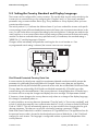
5.5 Setting the Country Standard and Display Language
The inverter can be configured for various countries. This can be done via two rotary switches in the
inverter prior to commissioning or by configuring the "CntrySet" and / or "Set country standard"
parameter using a communication device (e.g. Sunny WebBox or Sunny Explorer) after you have
commissioned the inverter.
The switch position 0 / 0 indicates the delivered state. If you have ordered the inverter with specific
country settings, these will have already been preset in the factory via a communication device. In this
case, you will not be able to recognize the setting by the switch position. If changes are made via the
rotary switches or via a communication device, these settings will be overwritten and cannot be easily
restored. For devices ordered without any specified country of installation, the standard setting is
"VDE0126-1-1" and the language is German.
Changes will be immediately accepted after switching the line circuit breaker on. If an
un‑programmed switch setting is selected, the inverter issues an error message.
Grid Guard Protected Country Data Sets
In some countries, the local power supply line requirements demand a mechanism which prevents the
parameters for grid feeding from being able to be changed. Some country data sets are therefore
protected and can only be unlocked with a personal access code, the so-called SMA Grid Guard Code.
Country data sets protected by Grid Guards are blocked automatically 10 feed-in hours after
commissioning or the last modification. If the country data set is changed after these 10 feed-in hours,
the inverter will not accept the changes and displays the error message "Grid parameter locked".
If, however, a later change to the country data set only relates to a change of the display language,
this change is immediately taken on.
It is also possible to set country data sets (parameter "CntrySet" and / or "Set country standard"), and
to lock or unlock these manually via a communication device. To lock, you have to set the Grid Guard
Code to "54321". This will automatically appear as an input window when changing the first gridrelevant parameter. The data set can only be unlocked by entering a personal, 10-digit
SMA Grid Guard Code which is valid for a maximum of 10 grid-feed hours. The application form for
the personal access code is located in the download area at www.SMA.de/en, in the "Certificate"
category for each inverter. The language is configurable without a password independent of the
country data set.
Installation Guide
WB36TL_50TL-IEN102011
39
Electrical Connection
SMA Solar Technology AG
Changing of parameters in grid guard protected country data sets
If the parameters within protected country data sets are changed, these are no longer
protected and instead of the standard, "ADJ" or "Special setting" is displayed. In this case,
the parameters are not changed automatically after 10 grid-feed hours, but have to be
manually locked. To manually lock the parameters, set the SMA Grid Guard Code to
"54321".
Further information on parameter settings
Detailed information on how to proceed with respect to setting and changing parameters
is available in the respective user manual for your software.
The last change (executed via switch or communication device) is always verified and activated if
applicable. Consequently, the switch position may not necessarily show the actual country
configuration.
5.5.1 Checking the Country Standard
Check whether the inverter is set to the installation country.
1. Check that the country standard is correct on the basis of the display message during
(re‑)commissioning (see section 6 ”Initial start-up” (page 50) or section 8 ”Restarting the
system” (page 62)) or by means of the "SMA grid guard" measuring channel via a
communication device.
2. If necessary, change the setting via the parameter "CntrySet" and / or "Set country standard"
using the communication device or the rotary switches (see section 5.5.2 ”Setting the Country
Standard and Language using Rotary Switches” (page 43)) according to the following table.
Display language
Once you have set the country standard, you can set the display language at any time
using rotary switch B. However, you have to then set the rotary switch A to "0" in order to
keep the country data set.
The settings of each country data set are specified in the operation parameters. The parameters can
be read out using a communication device. The description of the operating parameter is available
in the download area at www.SMA.de/en in the category "Technical Description" of the respective
inverter.
(A) (B) Country data set
Display language
0
0
Delivery state
Delivery state
0
1
Retained
English
0
2
Retained
German
40
WB36TL_50TL-IEN102011
Grid guard
protection
Dependent on
parameter set
Dependent on
parameter set
Dependent on
parameter set
Country
Dependent on
parameter set
Dependent on
parameter set
Dependent on
parameter set
Installation Guide
SMA Solar Technology AG
Electrical Connection
(A) (B) Country data set
Display language
0
3
Retained
French
0
4
Retained
Spanish
0
5
Retained
Italian
0
6
Retained
Not programmed**
0
7
Retained
Not programmed**
1
0
VDE0126-1-1
German
Grid guard
protection
Dependent on
parameter set
Dependent on
parameter set
Dependent on
parameter set
Dependent on
parameter set
Dependent on
parameter set
Yes
1
1
1
8
VDE0126-1-1 A a)
VDE0126-1-1
German
French
Yes
Yes
1
2
2
3
3
4
4
4
5
5
6
9
0
8
0
8
0
8
9
0
8
0
VDE0126-1-1 B b)
VDE0126-1-1
AS4777
DK5940E2.2
DK5940E2.2
RD1663
PPC
PPC*
Kepco guide
G 83/1
EN 50438
French
Italian
English
Italian
German
Spanish
Not programmed**
English
English
English
German
Yes
Yes
no
no
no
Yes
no
no
no
no
Yes
6
1
EN 50438
English
Yes
6
2
EN 50438
French
Yes
6
3
EN 50438
Italian
Yes
6
4
EN 50438
Spanish
Yes
6
5
EN 50438
Not programmed**
Yes
Installation Guide
Country
Dependent on
parameter set
Dependent on
parameter set
Dependent on
parameter set
Dependent on
parameter set
Dependent on
parameter set
Germany,
Switzerland,
Germany
Switzerland,
France
France
Switzerland
Australia
Italy
Italy
Spain
Greece
Greece
South Korea
England
various EU
countries
various EU
countries
various EU
countries
various EU
countries
various EU
countries
various EU
countries
WB36TL_50TL-IEN102011
41
Electrical Connection
SMA Solar Technology AG
(A) (B) Country data set
Display language
6
6
EN 50438
Not programmed**
Grid guard
protection
Yes
7
7
7
7
7
7
E
E
E
E
E
E
E
0
1
2
8
9
A
0
1
2
3
4
5
6
EN50438-CZ
EN50438-CZ
EN50438-CZ
C10/11*
C10/11*
C10/11*
Off-grid 60 Hz
Off-grid 60 Hz
Off-grid 60 Hz
Off-grid 60 Hz
Off-grid 60 Hz
Off-grid 60 Hz
Off-grid 60 Hz
Not programmed**
English
German
French
English
German
English
German
French
Spanish
Italian
Not programmed**
Not programmed**
Yes
Yes
Yes
Yes
Yes
Yes
no
no
no
no
no
no
no
Country
various EU
countries
Czech Republic
Czech Republic
Czech Republic
Belgium
Belgium
Belgium
Flexibility
Flexibility
Flexibility
Flexibility
Flexibility
Flexibility
Flexibility
a)
Special setting: parameter "VolCtl.Rpro" or "Voltage increase protection" = 244 V instead of 253 V
b)
Special setting: Bluetooth transmission power reduced (in accordance with French standards)
*)
Availability on request
**)
Currently unavailable. The previously configured display language remains set.
Should the inverter not be set to the installation country, configure it using the 2 rotary switches as
described in section 5.5.2 ”Setting the Country Standard and Language using Rotary Switches”
(page 43).
Alternatively you can adjust the settings via the parameter "CntrySet" and / or "Set country standard"
using a communication device.
If you require adjusted parameter settings for you installation location, you can change these using a
communication device.
42
WB36TL_50TL-IEN102011
Installation Guide
SMA Solar Technology AG
Electrical Connection
5.5.2 Setting the Country Standard and Language using Rotary
Switches
1. Disconnect the inverter as described in section 7 ”Disconnecting the Inverter” (page 59).
2. Set the arrows on both rotary switches (A and B)
using a screw driver (2.5 mm) to the desired
positions (see table in section 5.5.1 ”Checking the
Country Standard” (page 40)).
Jumper for English language
You can also set the language to English by
means of a jumper (e.g. for service purposes in
other countries). To do so, plug the jumper
onto the upper two pins as shown on the right.
3. Re-commission the inverter as described in section 8 ”Restarting the system” (page 62).
Installation Guide
WB36TL_50TL-IEN102011
43
Electrical Connection
SMA Solar Technology AG
5.6 Communication
Communication via Bluetooth with a communication device is activated as standard. Networking via
Bluetooth with other inverters is deactivated ex works.
The following setting options are possible via a rotary switch.
Switch position
(NetID)
0
1
2…F
Setting
Off
Communication via Bluetooth with communication device possible, no
networking with other inverters (factory setting)
Networking with other inverters
In order to restrict communication via Bluetooth between the inverters of your system and those of
neighboring systems, you can assign an individual NetID to the inverters of your system
(switch position 2 … F). This, however, is only necessary if neighboring systems are within a radius
of 500 m.
So that all inverters in your system are detected by your communication device, all inverters must have
the same NetID.
Procedure
1. Disconnect the inverter as described in section 7.2 ”Disconnect the device from voltage
sources” (page 59).
2. Set the arrow on the rotary switches to the required
position using a screwdriver (2.5 mm).
3. Re-commission the inverter as described in
section 8 ”Restarting the system” (page 62).
Acceptance of settings
The Bluetooth settings will only be activated after the line circuit breaker has been switched
on, the Windy Boy Protection Box connected and the Electronic Solar Switch plugged in.
44
WB36TL_50TL-IEN102011
Installation Guide
SMA Solar Technology AG
Electrical Connection
5.6.1 Multi-function relay
The inverter is equipped with a multi-function relay as standard. This can be activated, for instance,
simultaneously with the red error LED beside the display. Other functions are being planned can be
later retrofitted via a firmware update.
Here you can connect separate loads both in the event of errors and for trouble-free operation.
The following table gives you the maximum permissible voltages and currents:
AC
DC
Voltage
max. 240 V
max. 30 V
Current
max. 1.0 A
max. 1.0 A
Description
Cable type
External diameter
Cross section of insulated conductor
Strip insulation
Stripping length
Value
Double insulated
5 mm … 12 mm
0.08 mm² … 2.5 mm²
max. 8 mm
max. 15 mm
Cable requirements
Position
A
B
C
D
E
The cable type and cable-laying method must be appropriate to the application and location.
Line circuit breaker
If you are connecting the multi-function relay to the public grid, it must be protected with a separate
line circuit breaker.
Installation Guide
WB36TL_50TL-IEN102011
45
Electrical Connection
SMA Solar Technology AG
Connection plan
46
WB36TL_50TL-IEN102011
Installation Guide
SMA Solar Technology AG
Electrical Connection
Procedure
1. Disconnect the inverter as described in section 7.2 ”Disconnect the device from voltage
sources” (page 59).
2. Undo the lock nut of the cable gland a little and remove the filler plug from the cable conduit.
Seal in the cable gland
There is a two-part seal in the cable
connection. Remove the inner insert of the seal,
if required. This is required to route a thicker
cable.
The following guideline values apply:
• Cable diameter with seal and insert: 5 mm … 7 mm
• Cable diameter with seal and without insert: 7 mm …13 mm
DANGER!
Danger to life due to high voltages in the inverter.
• Use only cables that have been insulated several times.
• Remove a max. of 15 mm cable sheath.
3. Pull the cable through.
4. Strip a max. of 8 mm off the insulated wires.
5. Connect wires to the terminal using a screwdriver.
The connection plan shows where the wires must be
connected, depending on whether you require an
operating or an error message.
6. Tighten the lock nut firmly to the cable gland.
7. Re-commission the inverter as described in section 8 ”Restarting the system” (page 62).
8. Switch on supply voltage.
☑ The multifunction relay is now operational.
Installation Guide
WB36TL_50TL-IEN102011
47
Electrical Connection
SMA Solar Technology AG
5.6.2 Communication module
The inverter can be equipped with a communication module in order to engage in wire-linked
communication with special data acquisition devices (e.g. Sunny WebBox) or a PC with
corresponding software (e.g. Sunny Data Control).
A detailed circuit diagram and installation description can be found in the communication module
manual.
48
WB36TL_50TL-IEN102011
Installation Guide
SMA Solar Technology AG
Electrical Connection
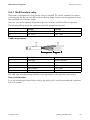
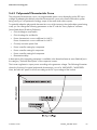
5.6.3 Polynomial Characteristic Curve
The polynomial characteristic curve is a programmable power curve depending on the DC input
voltage. By adapting the default polynomial characteristic curve to the small wind turbine system
being used, you can optimize the energy output of the small wind turbine system.
To optimally adapt the polynomial characteristic curve of the inverter to the wind turbine system being
used, you can change the following parameters on the PC with the "Sunny Explorer" software
(www.SMA.de/en/Products/Software):
• Critical voltage to start feed-in
• Critical voltage for end feed-in
• Power characteristic curves coefficient for Udc^0 …
Power characteristic curves coefficient for Udc^3
• Currently set active power limit
• Power controller settings kp component
• Power controller settings ki component
• Power controller settings kd component
• Deactivation delay
A description of the operating parameter is available in the download area at www.SMA.de/en in
the category "Technical Description" of the respective inverter.
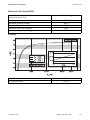
The inverter regulates its output power according to the generator voltage. The following illustration
shows the function of a typical polynomial characteristic curve of a WB 3600TL / WB 5000TL.
Here, the fed-in AC power is shown according to the DC input voltage of the inverter.
Installation Guide
WB36TL_50TL-IEN102011
49
Initial start-up
SMA Solar Technology AG
6 Initial start-up
Self test in accordance with DK 5940, Ed. 2.2 for initial start-up
(applies to Italy only)
The Italian DK 5940 standard requires that an inverter must only be connected to the
public grid if the disconnection times for overvoltage, undervoltage, minimum frequency
and maximum frequency have been checked.
If you have configured country standard DK5940E2.2, start the self-test as described in
section 6.1 ”Self-test according to DK 5940, ED. 2.2 (for Italy only)” (page 52). The test
takes approx. 3 minutes.
1. Check the following requirements before commissioning:
– Correct mounting and correct connection of the inverter
– The Windy Boy Protection Box (WBP-Box-500-11) is installed between
small wind turbine system and inverter
– Unnecessary DC inputs are closed with the corresponding DC plug connectors and sealing
plugs
– The line circuit breaker is laid out correctly
– Correct country configuration
– Correct grounding of the small wind turbine system in accordance with the instructions of the
manufacturer
– All housing passages are closed
2. Lock the bottom housing lid with the 6 screws.
Tighten the screws with 1.4 Nm torque in the order
shown in the figure on the right.
50
WB36TL_50TL-IEN102011
Installation Guide
SMA Solar Technology AG
Initial start-up
CAUTION!
The Electronic Solar Switch can be damaged if it is inserted incorrectly.
• Firmly connect the Electronic Solar
Switch.
• Check firm position of the Electronic
Solar Switch.
The handle of the
Electronic Solar Switch must be flush
with the housing.
3. Switch on the line circuit breaker.
4. Commission the small wind turbine system in accordance with the instructions of the
manufacturer.
5. If available, connect the supply voltage of the multi-function relay.
6. Check whether the display and LEDs are indicating a normal operating state.
LED
A
Color
Green
B
C
Red
Blue
Description
Glowing: operation
Flashing: network
connection conditions not
yet reached. The inverter
only switches to network if
the conditions are met.
Disturbance
Bluetooth communication is
active
☑ Successful commissioning is indicated by a glowing or blinking green LED.
The meaning of the illuminated red LED and the meaning of the event numbers on the display
are described in section 11.2 ”Error Messages” (page 71).
Installation Guide
WB36TL_50TL-IEN102011
51
Initial start-up
SMA Solar Technology AG
6.1 Self-test according to DK 5940, ED. 2.2 (for Italy only)
6.1.1 Starting the Self-Test by Tapping
You can start the self-test by tapping on the enclosure lid. Prerequisite here is that the country
configuration of the inverter has been set to Italy (DK5940E2.2) or a reconfiguration based on the
DK5940E2.2 country standard DK5940E2.2 has been performed. In addition, an undisturbed feedin operation must be possible.
Display Language during the Self-Test
Independent of the configured language (German or Italian), the display messages for the
self-test will always be displayed in Italian.
Procedure
1. Commission the inverter as described in section 6 ”Initial start-up” (page 50).
☑ The inverter is now in the initialization phase.
– Firstly, the firmware version of the internal processors appears in the text lines.
– After 5 seconds or after tapping the enclosure lid, the serial number or the description of
the inverter appears. The description of the inverter can be changed with a
communication device.
– After a further 5 seconds, or when you tap
again, the configured standard is displayed.
2. In order to start the self-test, tap the enclosure lid
within 10 seconds.
☑ The message shown on the right appears in the
display.
3. Now activate the self-test within 20 seconds by tapping on the enclosure lid again.
☑ Once you have started the test sequence, the inverter checks the disconnection times for
overvoltage, undervoltage, maximum frequency and minimum frequency on after the other.
During the tests, the inverter shows the values in the display which are described in
section 6.1.2 ”Test Sequence” (page 53). When the inverter has carried out the 4 tests, it
switches to normal operation. The original calibration values are reset.
52
WB36TL_50TL-IEN102011
Installation Guide
SMA Solar Technology AG
Initial start-up
6.1.2 Test Sequence
Note the values which are displayed during the test sequence. These values must be entered into a
test protocol. The test results of the individual tests are displayed 3 times one after the other.
Current values in the Display
During the self-test the actual voltage, the feed-in current and the frequency is displayed
above the text rows independent of the test values.
Overvoltage Test
The inverter begins with the overvoltage test and shows
the adjacent display message for 5 seconds.
During the test sequence, the voltage limit applied is
shown in the display of the inverter. The voltage limit is
reduced successively until the shut-down threshold is
achieved and the inverter disconnects from the grid.
Once the inverter has disconnected from the grid, the display successively shows the following values,
each for 10 seconds:
• Disconnection value,
• Calibration value,
• Reaction time.
The change between the first and second display takes places every 2.5 seconds.
Installation Guide
WB36TL_50TL-IEN102011
53
Initial start-up
SMA Solar Technology AG
Undervoltage Test
The undervoltage test follows the overvoltage test and the
inverter issues the adjacent display message for
5 seconds.
During the test sequence, the voltage limit applied is
shown in the display of the inverter. The voltage limit is
increased successively until the shutdown threshold is
reached and the inverter disconnects from the grid.
Once the inverter has disconnected from the grid, the display successively shows the following values,
each for 10 seconds:
• Disconnection value,
• Calibration value,
• Reaction time.
The change between the first and second display takes places every 2.5 seconds.
54
WB36TL_50TL-IEN102011
Installation Guide
SMA Solar Technology AG
Initial start-up
Maximum Frequency
The maximum frequency test follows the undervoltage test
and the inverter issues the adjacent display message for
5 seconds.
During the test sequence, the frequency limit applied is
shown in the display of the inverter. The frequency limit is
reduced successively until the shutdown threshold is
reached and the inverter disconnects from the grid.
Once the inverter has disconnected from the grid, the display successively shows the following values,
each for 10 seconds:
• Disconnection value,
• Calibration value,
• Reaction time.
The change between the first and second display takes places every 2.5 seconds.
Installation Guide
WB36TL_50TL-IEN102011
55
Initial start-up
SMA Solar Technology AG
Minimum Frequency
After the maximum frequency test, the minimum frequency
test takes place and the inverter shows the adjacent
display message for 5 seconds.
During the test sequence, the frequency limit applied is
shown in the display of the inverter. The frequency limit is
increased successively until the shutdown threshold is
reached and the inverter disconnects from the grid.
Once the inverter has disconnected from the grid, the display successively shows the following values,
each for 10 seconds:
• Disconnection value,
• Calibration value,
• Reaction time.
The change between the first and second display takes places every 2.5 seconds.
6.1.3 Interruption of the Self-Test
If, during the self-test, an unexpected disconnection requirement occurs, the self-test is interrupted. The
same applies if the DC voltage is so low that the feed-in can not be continued.
• The inverter then shows the adjacent display
message for 10 seconds.
• Restart the self-test as described in the following section 6.1.4 ”Restarting the Self-Test”
(page 57).
56
WB36TL_50TL-IEN102011
Installation Guide
SMA Solar Technology AG
Initial start-up
6.1.4 Restarting the Self-Test
In order to restart the self-test, proceed as follows:
1. Disconnect the line circuit breaker and secure against re-connection.
2. Disconnect the multi-function relay power supply, if available.
3. Disconnect the Electronic Solar Switch from the inverter for 5 minutes and then connect it again.
☑ The inverter is now in the initialization phase and you can restart the self-test, as described in
section 6.1.1 ”Starting the Self-Test by Tapping” (page 52) from point 3.
6.2 Display Messages during Initialization
• Firstly, the firmware version of the internal
processors appears in the text lines.
• After 5 seconds or after tapping the enclosure lid,
the serial number or the description of the inverter
appears. This description can be changed with a
communications device.
• After a further 5 seconds, or when you tap again,
the configured standard is displayed.
• After a further 5 seconds, or when you tap again,
the configured language is displayed.
• In normal operation the scrolling line of the display is subsequently empty. You can refer to the
possible event messages in the scrolling lines and their meaning in section 11 ”Messages”
(page 70).
Installation Guide
WB36TL_50TL-IEN102011
57
Initial start-up
SMA Solar Technology AG
6.3 Operating Conditions of the Inverter
Startup Procedure
If the inverter has enough voltage and power, the startup process is displayed by means of
simultaneous lighting of the three LEDs on the inverter.
As soon as the DC input voltage value defined in the "Vpv-Start" or "Critical voltage to start feed‑in"
parameter is reached, the inverter starts a number of self-tests and measurement processes and
synchronizes with the grid. This operating mode is indicated by the green LED flashing on the inverter.
When the tests are successfully completed and the DC input voltage is above "Vpv-Start" or
"Critical voltage to start feed-in", for the time configured in "T-Start" or "Start delay input" the inverter
connects to the grid, connects to the characteristic curve mode and the green LED lights up.
Characteristic Curve Operation
The inverter controls the input current depending on the alternator voltage.
The inverter then begins to put a load on the small wind turbine system, takes power from the small
wind turbine system according to the present input voltage and then feeds it into the grid. The
maximum output corresponds to the maximum AC power of the inverter. However, it can be reduced
using the "Pmax" or "Currently set active power limit" parameter.
Shutdown
If the wind strength is so low that the DC input voltage falls below an internally calculated value, then
the inverter stops feeding power into the mains grid for the period defined in "T‑Stop" or
"Deactivation delay". When the DC input voltage increases again, the inverter switches back to
characteristic curve operation.
If the DC input voltage remains below an internally calculated value for the time set in "T‑Stop" or
"Deactivation delay", the inverter will switch off.
If the DC input voltage is so low that it is no longer sufficient to supply the on-board electronics with
power, the inverter turns itself off immediately.
58
WB36TL_50TL-IEN102011
Installation Guide
SMA Solar Technology AG
Disconnecting the Inverter
7 Disconnecting the Inverter
7.1 Safety
DANGER!
Danger to life due to high voltages in the inverter.
The inverter operates at high voltages.
• Disconnect the inverter as described in the following section.
7.2 Disconnect the device from voltage sources
1. Stop the small wind turbine system and secure against restart.
2. Disconnect the line circuit breaker and secure against re-connection.
3. Disconnect the multi-function relay, if available.
4. Remove the Electronic Solar Switch.
5. Wait until LEDs, display and if applicable the fault indicator have gone off.
DANGER!
Danger to life due to high voltages in the inverter.
The capacitors in the inverter require 5 minutes to discharge.
• Wait 5 minutes before opening the inverter.
Installation Guide
WB36TL_50TL-IEN102011
59
Disconnecting the Inverter
SMA Solar Technology AG
6. Loosen all six captive screws and remove the
bottom housing lid.
7. Ensure there is no current at any DC cables using a
clip-on ammeter.
☑ If there is a current present, check the
installation.
8. Unlock the connected DC plug connectors using a
screwdriver:
– Insert a screwdriver into one of the slits on the
sides (1).
– Lever the screwdriver upward (2) and pull out
the plug connector (3).
60
WB36TL_50TL-IEN102011
Installation Guide
SMA Solar Technology AG
Disconnecting the Inverter
9. Verify the absence of voltage L with respect to N at
the AC terminal with an appropriate meter.
☑ If there is a voltage present, check the
installation.
10. Verify the absence of voltage L with respect to PE at
the AC terminal with an appropriate meter.
☑ If there is a voltage present, check the
installation.
11. Verify the absence of voltage to ground at the
multifunction relay.
☑ If there is a voltage present, check the
installation.
Installation Guide
WB36TL_50TL-IEN102011
61
Restarting the system
SMA Solar Technology AG
8 Restarting the system
1. Check the DC plug connector for correct polarity.
2. Connect one positive and one negative DC plug
connector each to both input areas on the inverter.
To release the DC plug connectors see
section 7.2 ”Disconnect the device from voltage
sources” (page 59).
Never connect all four DC plug connectors to only
one input area!
3. To create the seal on the inverter, all DC inputs that
are not required must be closed as follows:
– Insert the sealing plugs provided into the DC
plug connectors that are not needed. Do not
insert the sealing plugs into the DC inputs on the
inverter.
– Insert the DC plug connectors with sealing plugs
into the corresponding DC inputs on the inverter.
62
WB36TL_50TL-IEN102011
Installation Guide
SMA Solar Technology AG
Restarting the system
4. Lock the bottom housing lid with the 6 screws.
Tighten the screws with 1.4 Nm torque in the order
shown in the figure on the right.
5. Check the Electronic Solar Switch for wear, as described in section 9.2 ”Checking the Electronic
Solar Switch (ESS) for Wear” (page 68).
CAUTION!
Damage to the Electronic Solar Switch by incorrect connection.
• Firmly connect the Electronic Solar
Switch.
• Check firm position of the Electronic
Solar Switch.
The handle of the
Electronic Solar Switch must be flush
with the housing.
6. If available, switch on the supply voltage of the multi-function relay.
7. Switch on the line circuit breaker.
8. Commission the small wind turbine system in accordance with the instructions of the
manufacturer.
Installation Guide
WB36TL_50TL-IEN102011
63
Restarting the system
SMA Solar Technology AG
9. Check whether the display and LEDs are indicating a normal operating state.
LED
A
Color
Green
B
C
Red
Blue
Description
Glowing: operation
Flashing: network
connection conditions not
yet reached. The inverter
only connects to the grid if
conditions have been met.
Disturbance
Bluetooth communication is
active
☑ The green LED flashes or lights up in the event of successful recommissioning and the inverter
starts initialization (see section 6.2 ”Display Messages during Initialization” (page 57)).
The meaning of the illuminated red LED and the meaning of the event numbers on the display
are described in section 11.2 ”Error Messages” (page 71).
64
WB36TL_50TL-IEN102011
Installation Guide
SMA Solar Technology AG
Maintenance and Cleaning
9 Maintenance and Cleaning
9.1 Checking Heat Dissipation
If the inverter regularly reduces its output due to too high warming (temperature symbol on the display
illuminates), this can be caused by various factors. Please see the following table for the various
causes and measures.
Cause
Action
The cooling fins on the rear side of the enclosure • Clean the cooling fins with a soft brush.
are clogged with dirt.
The ventilation ducts at the top are clogged with • Clean the ventilation ducts with a soft brush.
dirt.
The fan is clogged with dirt.
• Clean fan as described in the following
section.
9.1.1 Cleaning the Fan
If the fan enclosure is soiled with loose dust, it can be cleaned using a vacuum cleaner. If you do not
achieve satisfactory results with a vacuum cleaner, dismantle the fans for cleaning.
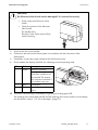
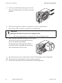
Procedure
1. Disconnect the inverter as described in section 7 ”Disconnecting the Inverter” (page 59).
2. Wait for the fan to stop rotating.
3. Unlock and remove fan plugs (A).
4. Push both fastening clips of the fan (B) towards the
fan and remove the housing with the fan.
Installation Guide
WB36TL_50TL-IEN102011
65
Maintenance and Cleaning
SMA Solar Technology AG
5. Push the top and bottom fastening clip on the fan
(C) to the outside and press out of the housing from
the back.
6. Clean the housing with a soft brush, a paint brush, a cloth or compressed air.
7. Clean the fan with a soft brush, a paint brush, or a damp cloth.
CAUTION!
Damage to the fan due to the use of compressed air.
• Do not use compressed air to clean the fan. This can damage the fan.
8. After cleaning, reassemble everything in reverse order.
The arrows on the fan housing and the fan must
point to the right during assembly.
The fastening clips on the right side of the fan
housing must catch underneath the housing wall
when inserting them into the inverter.
9. Re-commission the inverter as described in section 8 ”Restarting the system” (page 62).
☑ The fan has been cleaned and the inverter is back in operation.
10. Check the functioning of the fans as described in the following section.
66
WB36TL_50TL-IEN102011
Installation Guide
SMA Solar Technology AG
Maintenance and Cleaning
9.1.2 Checking the Fans
Checking the Fan
To test the fans you will need a special data logging device (e.g. Sunny WebBox) or a PC
with appropriate software (e.g. Sunny Explorer) in order to change the parameters of the
inverter.
You will also require the installer password to access installer mode.
1. Request installer password from the SMA Serviceline (contact see page 92).
2. Set parameters "CoolSys.FanTst" and / or "Fan test" to "On" in installer mode.
3. Check the air-flow of the fan.
The inverter takes in air at the bottom and it comes out again at the top. Listen for any unusual
noise that could indicate incorrect installation or that the fan is faulty.
4. Set parameters "CoolSys.FanTst" and / or "Fan test" to "Off" again.
☑ The fan test has been completed.
Installation Guide
WB36TL_50TL-IEN102011
67
Maintenance and Cleaning
SMA Solar Technology AG
9.2 Checking the Electronic Solar Switch (ESS) for Wear
Check the Electronic Solar Switch for wear before plugging it in.
Result
☑ The metal tongues inside the
connector are not damaged or
discolored.
Action
• Insert the handle of the Electronic Solar Switch
securely in the socket on the underside of the
enclosure.
• Re-commission the inverter as described in
section 8 ”Restarting the system” (page 62).
The Electronic Solar Switch can no longer safely
☑ The metal tongues inside the
connector have a brown
disconnect the DC side.
discoloration or are burned through. • Replace the Electronic Solar Switch handle before
attaching it again (for the order number see
section 15 ”Accessories” (page 91).
• Re-commission the inverter as described in
section 8 ”Restarting the system” (page 62).
68
WB36TL_50TL-IEN102011
Installation Guide
SMA Solar Technology AG
Slot for SD card
10 Slot for SD card
The inverter is equipped with an SD card slot. The slot is on the left below the display.
There are a number of cases which require an SD card to be read in, such as:
• Under consultation with the SMA Serviceline, a firmware update is necessary.
SMA Solar Technology AG will send you a file with the firmware update per e-mail.
You will find the description of the Firmware update in the download area at www.SMA.de/en.
• You require adjusted parameter settings for you installation location.
Request these from SMA Solar Technology AG. SMA Solar Technology AG will then send you
a file with the relevant settings and instructions on how to install these per e-mail.
• Enter the Grid Guard Code to set a new country standard with the rotary switch or to be able
to change parameters. If required, request a manual on the procedure from
SMA Solar Technology AG or it is shipped with the necessary data.
Properties of the SD Card
Use an SD card with a maximum capacity of 2 GB.
Use the SD card exclusively for this inverter. Do not save any multimedia files or other
unsuitable files on the SD card.
Installation Guide
WB36TL_50TL-IEN102011
69
Messages
SMA Solar Technology AG
11 Messages
11.1 Event messages
During an update, the relevant display message is shown in the text line of the display.
Display
< Inst. code valid >
Description
The Grid Guard Code entered is valid.
The configured country data set is now unblocked
and can be changed.
< No new update SDcard >
< Grid param.unchanged >
< Parameters set successfully >
< SD card is read >
< Set parameter >
< Update completed >
< Update Bluetooth >
< Update display >
< Update main CPU >
< Update communication >
< Update RS485I module >
< Upd. language table >
< Update file OK >
70
WB36TL_50TL-IEN102011
If the configured country data set is protected, the
unlocking is valid for a maximum of 10 feed-in
hours.
There is no update relevant for this inverter on the
SD card or the present update has already been
installed.
The selected switch setting is not programmed or
there is no country data set available on the SD
card.
A new country data set has been configured.
The inverter is currently reading the SD card.
The inverter sets the adjusted parameters.
The inverter has successfully completed the
update.
Successful update of the Bluetooth components.
Successful display update.
Successful update of inverter component.
Successful update of communication component.
Successful update of communication interface.
Successful update of language table.
The file found is valid.
Installation Guide
SMA Solar Technology AG
Messages
11.2 Error Messages
When errors occur, a display message including the corresponding event number will appear in the
text line of the display. By tapping on the enclosure lid, multi-line messages can be switched further.
If the error persists for a prolonged period, the red LED lights on and the fault signaling contact is
activated.
Event no. Cause
1
< Grid fault >
2
Corrective measures
• Check the grid voltage and grid
connection on the inverter.
The grid voltage has exceeded the
permissible range. This error can have the If the grid voltage lies outside the
acceptable range because of local grid
following causes:
conditions, ask the utility operator if the
• The grid voltage at the point of
connection of the inverter is too high. voltage can be adjusted at the feed-in point
or if he agrees to changes in the values of
• Grid impedance at the terminal of the
the monitored operational limits.
inverter is too high.
If the grid voltage lies within the tolerance
For safety reasons, the inverter disconnects
range, yet this error is still being displayed,
itself from the grid.
contact the SMA Serviceline.
• Check the triggering of the line circuit
< Grid fault >
breaker.
The grid voltage has fallen below the
permissible range. This error can have the
following causes:
• Check the grid current and the grid
connection on the inverter.
If the grid voltage lies outside the
acceptable range because of local grid
• AC cable damaged
conditions, ask the utility operator if the
• The grid voltage at the point of
voltage can be adjusted at the feed-in point
connection of the inverter is too low.
or if he agrees to changes in the values of
For safety reasons, the inverter disconnects the monitored operational limits.
itself from the grid.
If the grid voltage lies within the tolerance
range, yet this error is still being displayed,
contact the SMA Serviceline.
• Grid disconnected
Installation Guide
WB36TL_50TL-IEN102011
71
Messages
SMA Solar Technology AG
Event no. Cause
3
< Grid fault >
4
5
Corrective measures
• Check the grid voltage at the point of
connection of the inverter:
The average grid voltage over 10 minutes
is no longer within the permissible range. If due to local grid conditions the grid
voltage exceeds the configured limiting
This can have the following causes:
value, ask the utility operator whether the
• The grid voltage at the point of
voltage can be adjusted at the feed-in
connection of the inverter is too high.
point, or whether he will agree to a
• Grid impedance at the terminal of the modification of the limiting value for
inverter is too high.
voltage quality monitoring.
The inverter disconnects to assure
If the grid voltage is continually within the
compliance with the voltage quality of the acceptable range, and this error is still
grid.
displayed, contact the SMA Serviceline.
< Grid fault >
• Check the power supply line for
strong, short-term frequency
The inverter has left the grid parallel
variations.
operation and for safety reasons
interrupted feeding-in.
< Grid fault >
• If possible, check the grid frequency
and observe how often major
deviations occur.
The grid frequency is not within the
permissible range. For safety reasons, the
inverter disconnects itself from the grid.
If repeated frequency variations occur and
as a result this error occurs, ask the grid
operator if it would agree to modify the
operating parameter.
6
< Grid fault >
The internal inverter monitoring has
detected an impermissibly high proportion
of direct current in the grid current.
7
< Frq. not permitted >
The grid frequency has left the allowable
range. For safety reasons, the inverter
disconnects itself from the grid.
Discuss the proposed parameters with the
SMA Serviceline.
• Check the power supply line for
direct current.
• If this is a recurrent phenomenon,
check with the grid operator whether
it is possible to raise the limiting value
of monitoring.
• As far as possible, check the grid
frequency and observe how often
major fluctuations occur.
If repeated frequency variations occur and
as a result this error occurs, ask the grid
operator if it would agree to modify the
operating parameter.
Discuss the proposed parameters with the
SMA Serviceline.
72
WB36TL_50TL-IEN102011
Installation Guide
SMA Solar Technology AG
Event no. Cause
8
< Grid failure >
9
• Check AC installation.
< PE conn. missing >
• Check whether there is a general
black-out.
• Check AC installation.
< L / N swapped >
11
< Installation fault >
< 2nd phase conn. to N >
< Unstable operation >
The supply at the DC input of the inverter is
not sufficient for stable operation.
34
Corrective measures
• Check fuse.
< Waiting for grid voltage >
10
33
Messages
< DC overvoltage >
The DC input voltage connected to the
inverter is too high.
• Connect the PE cable to the AC
terminal as described in
section 5.3.2 ”Connecting the
Inverter to the Power Distribution
Grid (AC)” (page 29).
• Adjust the connection as described in
section 5.3.2 ”Connecting the
Inverter to the Power Distribution
Grid (AC)” (page 29).
• Adjust the connection as described in
section 5.3.2 ”Connecting the
Inverter to the Power Distribution
Grid (AC)” (page 29).
• Wait for higher and more constant
wind speeds.
• If the event reoccurs in the event of
medium-high and more constant
wind speeds, check the layout of the
small wind turbine system.
• Disconnect inverter from
Windy Boy Protection Box
immediately as described in
section 7.2 ”Disconnect the
device from voltage sources”
(page 59)! Otherwise, the
inverter may be destroyed.
• Before reconnecting the inverter to
the Windy Boy Protection Box, check
that the maximum input voltage of the
inverter and check the DC voltage of
the Windy Boy Protection Box when
operating the
small wind turbine system.
Installation Guide
WB36TL_50TL-IEN102011
73
Messages
SMA Solar Technology AG
Event no. Cause
35
< Insulation resist. >
Corrective measures
• Check small wind turbine system for
ground fault as described in
The inverter has detected a ground fault in
section 12.1 ”Checking the Small
the system.
Wind Turbine System for a Ground
Fault” (page 77).
36
< High discharge curr. >
The leakage current of the inverter and the
small wind turbine system is too high.
This can be caused by a sudden grounding
fault, failure current or an actual fault in the
device.
37
The inverter interrupts grid feed
immediately after exceeding a limiting
value and then automatically re-connects
to the grid.
< Resid.curr.too.high >
• Have the ground fault rectified by the
installer of the small
wind turbine system before
reconnecting the affected cable.
• Check small wind turbine system for
ground fault as described in
section 12.1 ”Checking the Small
Wind Turbine System for a Ground
Fault” (page 77).
• Have the ground fault rectified by the
installer of the
small wind turbine system before
reconnecting the affected cable.
• Check small wind turbine system for
ground connection as described in
section 12.1 ”Checking the Small
Wind Turbine System for a Ground
Fault” (page 77).
• Have the ground fault rectified by the
installer of the small
wind turbine system before
reconnecting the affected cable.
If this event occurs often:
38
< DC overcurrent >
39
An overcurrent condition occurs on the DC
side of the inverter and it switches off.
< Waiting for DC start conditions >
• Check layout and connections of the
small wind turbine system.
• Wait for higher wind speeds.
The input cable or input voltage of the
small wind turbine system is still insufficient
for feeding into the grid.
• If the event reoccurs in the event of
medium-high wind speeds, check the
layout of the
small wind turbine system.
• Contact the SMA Serviceline (see
section 16 ”Contact” (page 92)).
60 - 64
< Interference device >
74
WB36TL_50TL-IEN102011
Installation Guide
SMA Solar Technology AG
Event no. Cause
65
< Overtemperature >
Inverter switches off due to excess
temperature.
66
< Overload >
67
< Comm. disturbed >
68 - 70
A fault has occurred in the internal
communication of the inverter. However,
the inverter continues feeding into the grid.
< Interference device >
71
< SD card defective >
< Parameter file not found or defective >
< Param. setting failed >
< Update file defect. >
< No update file found >
72
< Data stor. not poss. >
Internal device fault: however, the inverter
continues to feed in.
Installation Guide
Messages
Corrective measures
• Ensure sufficient ventilation.
• Check heat dissipation, as described
in section 9.1 ”Checking Heat
Dissipation” (page 65).
• Contact the SMA Serviceline (see
section 16 ”Contact” (page 92)).
If this event occurs often:
• Contact the SMA Serviceline (see
section 16 ”Contact” (page 92)).
• Contact the SMA Serviceline (see
section 16 ”Contact” (page 92)).
Re-format the SD card.
• Re-save the files to the SD card.
• Copy the parameter file into the card
drive:\PARASET directory.
• Check the parameters for valid
values.
• Ensure authentication for
modification with Grid Guard Code.
• Re-format the SD card.
• Re-save the files to the SD card.
• Copy the update file into the SD card
drive:\UPDATE directory.
• If this fault occurs often, contact the
SMA Serviceline (see
section 16 ”Contact” (page 92)).
WB36TL_50TL-IEN102011
75
Messages
SMA Solar Technology AG
Event no. Cause
73
< Update main CPU failed >
Internal device fault.
< Update RS485I module failed >
Internal device fault: however, the inverter
continues to feed in.
< Update BT failed >
Corrective measures
• Contact the SMA Serviceline (see
section 16 ”Contact” (page 92)).
• Retry update.
• If this fault occurs again, contact the
SMA Serviceline (see
section 16 ”Contact” (page 92)).
Internal device fault: however, the inverter
continues to feed in.
< Upd. display failed >
Internal device fault: however, the inverter
continues to feed in.
< Update language table failed >
74
Internal device fault: however, the inverter
continues to feed in.
< Varistor defective >
80
< Derating occurred >
The delivered power of the inverter was
reduced below nominal power due to a
too-high temperature for more than
10 minutes.
90
< Inst. Code invalid >
The entered installer code (personal) is
invalid.
< Grid param. locked >
The actual country data set is locked.
< Waiting for main CPU >
• DC voltage at the DC input is not
sufficient to run the main computer.
• The selected rotary switch setting for
the country configuration is not
programmed.
• Check the varistors as described in
section 12.2 ”Checking the
Functioning of the Varistors”
(page 80).
If this event occurs often:
• Ensure sufficient ventilation.
• Check heat dissipation, as described
in section 9.1 ”Checking Heat
Dissipation” (page 65).
• Enter valid Grid Guard Code.
• Enter valid Grid Guard Code to
change the country data set.
• Ensure sufficient DC voltage (green
LED lights up or flashes).
• Check the setting of the rotary
switches (see section 5.4.2).
• Enter Grid Guard Code.
• The parameters to be changed are
protected.
76
WB36TL_50TL-IEN102011
Installation Guide
SMA Solar Technology AG
Troubleshooting
12 Troubleshooting
12.1 Checking the Small Wind Turbine System for a Ground Fault
If the inverter displays event numbers "35", "36" or "37", there is a high probability of a ground fault
in the system.
Check the small wind turbine system for ground connection as described below:
DANGER!
Danger to life due to high voltages in the inverter.
• Stop the small wind turbine system and secure against restart.
• Disconnect the line circuit breaker and secure against re-connection.
• Disconnect the multi-function relay, if available.
1. Remove the Electronic Solar Switch.
2. Wait until LEDs, display and if applicable the fault indicator have gone off.
DANGER!
Danger to life due to high voltages in the inverter.
The capacitors in the inverter require 5 minutes to discharge.
• Wait 5 minutes before opening the inverter.
Installation Guide
WB36TL_50TL-IEN102011
77
Troubleshooting
SMA Solar Technology AG
3. Loosen all six captive screws and remove the
bottom housing lid.
4. Unlock the connected DC plug connectors using a
screwdriver:
– insert a screwdriver into one of the slits on the
sides (1).
– Lever the screwdriver upward (2) and pull out
the plug connector (3).
5. Verify the absence of voltage L with respect to N at
the AC terminal with an appropriate meter.
☑ If there is a voltage present, check the
installation.
78
WB36TL_50TL-IEN102011
Installation Guide
SMA Solar Technology AG
Troubleshooting
6. Verify the absence of voltage L with respect to PE at
the AC terminal with an appropriate meter.
☑ If there is a voltage present, check the
installation.
7. Verify the absence of voltage to ground at the
multifunction relay.
☑ If there is a voltage present, check the
installation.
8. Disconnect L1, L2 and L3 of the small wind turbine system from the Windy Boy Protection Box.
9. Measure the resistance between L1 of the small wind turbine system and the ground potential.
10. Measure the resistance between L2 of the small wind turbine system and the ground potential.
11. Measure the resistance between L3 of the small wind turbine system and the ground potential.
Result
The measured resistance is virtually infinite.
☑ There is no ground fault at the small
wind turbine system.
The measured resistance is very small
(< 10 Ω ).
☑ There is no ground fault at the small
wind turbine system.
Installation Guide
Action
The his probably a ground fault in the
Windy Boy Protection Box or in the supply
cables to the inverter.
• Disconnect the Windy Boy Protection Box
from the inverter and measure resistance
of all connectors and the ground
potential.
• Have the ground fault rectified by the
installer of the small wind turbine system
before reconnecting the small wind
turbine system to the Windy Boy
Protection Box.
WB36TL_50TL-IEN102011
79
Troubleshooting
SMA Solar Technology AG
12.2 Checking the Functioning of the Varistors
If the inverter displays event number "74", one of the varistors has probably lost its protective function
due to repeated stress.
Check the varistors as described below:
1. Disconnect the inverter as described in section 7.2 ”Disconnect the device from voltage
sources” (page 59).
DANGER!
Danger to life due to high voltages in the inverter.
The capacitors in the inverter require 5 minutes to discharge.
• Wait 5 minutes before opening the housing cover, in order to allow time for the
capacitors to discharge!
2. Undo the screws of the top housing lid.
3. Pull the housing lid to the front at the bottom edge.
4. Push the housing lid to the top and remove it.
80
WB36TL_50TL-IEN102011
Installation Guide
SMA Solar Technology AG
Troubleshooting
CAUTION!
Electrostatic discharges can damage the inverter.
Components on the inside of the inverter may be irreparably damaged due to electrostatic
discharge.
• Ground yourself before touching a component.
Position of Varistors
See the following illustration to determine the position of the varistors.
Observe the following allocation of the
terminals:
• Terminal A: outer terminal
(Varistor connection with loop [crimp])
• Terminal B: middle terminal
• Terminal C: outer terminal
(Varistor connection without loop
[crimp])
5. Use a Multimeter to ensure that all of the varistors
in the installed state have a conducting connection
between connectors B and C.
Event
Action
☑ There is a conductive connection. There is probably a different fault in the inverter.
• Continue with point 9.
• Contact the SMA Serviceline (see
section 15 ”Accessories” (page 91)).
Installation Guide
WB36TL_50TL-IEN102011
81
Troubleshooting
SMA Solar Technology AG
Event
☑ There is no conductive
connection.
Action
The respective varistor is defective and must be replaced.
Varistor failure is generally due to influences which affect
all varistors similarly (temperature, age, induced
overvoltage). SMA Solar Technology AG recommends
that you replace both varistors.
The varistors are specially manufactured for use in the
inverter and are not commercially available. Spare
varistors must be ordered directly from
SMA Solar Technology AG (see
section 15 ”Accessories” (page 91)).
• To replace the part, proceed to step 6.
6. Insert an insertion tool into the openings of the
terminal contacts (1).
☑ This releases the terminals.
If you do not receive an insertion tool for operating
the terminal clamps with your replacement
varistors, contact SMA Solar Technology AG. As
an alternative, the terminal contacts can be
operated using a 3.5 mm wide screwdriver.
7. Remove the varistor (2).
8. Insert new varistor (3).
The pole with the small loop (crimp) must be fitted
to terminal A when remounting (3).
9. Align the housing lid vertically.
82
WB36TL_50TL-IEN102011
Installation Guide
SMA Solar Technology AG
Troubleshooting
10. Fasten the screws and the washers half way.
11. Press the housing lid onto the housing until it catches
at the top.
12. Fasten both screws of the housing lid to a tightening
torque of 2.4 Nm.
13. Close the bottom housing lid and recommission the
inverter as described in section 8 ”Restarting the
system” (page 62).
☑ The check and replacement of the varistors is
completed.
Installation Guide
WB36TL_50TL-IEN102011
83
Decommissioning
SMA Solar Technology AG
13 Decommissioning
13.1 Dismantling the Inverter
1. Disconnect the inverter and open the bottom housing lid as described in section 7.2 ”Disconnect
the device from voltage sources” (page 59).
2. Remove all cables from the inverter.
CAUTION!
Danger of burn injuries due to hot enclosure parts.
• Wait 30 minutes for the housing to cool down.
3. If mounted with top hat rail: undo screw between wall and housing.
4. Disconnect the anti-theft protection, if applicable.
5. Push the inverter to the left and remove from the wall-mount or the top hat rail.
13.2 Packing the Inverter
If possible, always pack the inverter in its original packaging. If it is no longer available, you can also
use an equivalent carton. The box must be capable of being closed completely and made to support
both the weight and the size of the inverter.
13.3 Storing the Inverter
Store the inverter in a dry place where ambient temperatures are always between
− 25 °C and +60 °C.
13.4 Disposing of the Inverter
Dispose of the inverter at the end of its service life in accordance with the disposal regulations for
electronic waste which apply at the installation location at that time. Alternatively, send it back to SMA
Solar Technology AG with shipping paid by sender, and labeled "ZUR ENTSORGUNG"
("FOR DISPOSAL") (contact see section 16 ”Contact” (page 92)).
84
WB36TL_50TL-IEN102011
Installation Guide
SMA Solar Technology AG
Technical Data
14 Technical Data
14.1 Windy Boy 3600TL
DC Input
Maximum DC voltage
MPP input voltage range
Maximum open circuit voltage to activate "Turbine Mode"
DC nominal voltage
Maximum input current
Maximum DC power
Voltage ripple
550 V
80 V … 440 V
125 V
400 V
2 x 15 A
3,800 W
< 10 % of the input voltage
AC Output
Nominal AC power
Maximum AC power
Nominal AC current
Maximum output current
Maximum fuse protection
Harmonic distortion of output current at
3,600 W
3,600 W
15.7 A
22 A
32 A
<3%
AC THD voltage < 2 %,
AC power > 0.5 AC nominal power
Nominal AC voltage
AC voltage range, extended operating range*
AC grid frequency*
Tolerance at AC grid frequency
Power factor at nominal AC power
Overvoltage category
Test voltage at 50 Hz
(1 s routine testing / 5 s type testing)
Surge testing voltage
Serial interface
Internal consumption in standby
220 V / 230 V / 240 V
180 V … 280 V
50 Hz / 60 Hz
± 5 Hz
1
III
1.4 kV
4 kV
6 kV
< 0.5 W
* Depends on country configuration
Installation Guide
WB36TL_50TL-IEN102011
85
Technical Data
SMA Solar Technology AG
Mechanical Data
Width x height x depth
Weight
470 mm x 445 mm x 180 mm
25 kg
Climatic Conditions
Extended temperature range *
Extended humidity range *
Extended air pressure range *
Temperature range **
Operating temperature range
Maximum operating altitude above mean sea level
− 25 °C … +60 °C
0 % … 100 %
79.5 kPa … 106 kPa
− 25 °C … +70 °C
− 25 °C … +60 °C
2,000 m
* according to DIN EN ISO 50178:1998-04, installation type C, class 4K4H
** according to DIN EN ISO 50178:1998-04, transport type E, class 2K3
Features
Topology
Cooling concept
Transformerless
OptiCool
General data
Electronics protective rating*
Connection area protection rating*
Protection class
Noise emission (typical)
IP65
IP54
I
≤ 25 dB(A)
* according to IEC 60529
Protective Devices
All-pole DC disconnection unit
DC overvoltage protection
Personal protection (Riso > 1 M Ω )
Reverse-polarity protection
AC short circuit protection
All-pole AC disconnection unit
Electronic Solar Switch,
DC plug system SUNCLIX
Thermally monitored varistors
Insulation monitoring
Short-circuit diode
Current control
Automatic disconnection device
SMA Grid Guard 3
Communication Interfaces
RS485, galvanically isolated
Bluetooth® Wireless Technology
86
WB36TL_50TL-IEN102011
optional
Standard
Installation Guide
SMA Solar Technology AG
Technical Data
Electronic Solar Switch (ESS)
Electrical service life in the event of a short circuit, with a
nominal current of 35 A
Maximum switching current
Maximum switching voltage
Maximum PV power
Protection rating when plugged
Protection rating when unplugged
A minimum of 50 switching operations
35 A
800 V
12 kW
IP65
IP21
Efficiency
Peak efficiency
European efficiency
Installation Guide
97.0 %
96.3 %
WB36TL_50TL-IEN102011
87
Technical Data
SMA Solar Technology AG
14.2 Windy Boy 5000TL
DC Input
Maximum DC voltage*
MPP input voltage range
Minimum open circuit voltage to activate "Turbine Mode"
DC nominal voltage
Maximum input current
Maximum DC power
Voltage ripple
550 V
80 V … 440 V
125 V
400 V
2 x 15 A
5,300 W
< 10 % of the input voltage
* The maximum open circuit voltage, which can occur at a cell temperature of −10 °C, may not exceed the maximum input voltage.
AC Output
AC nominal output*
Maximum AC power
Nominal AC current
Maximum output current
Maximum fuse protection
Harmonic distortion of output current at
4,600 W / 5,000 W
5,000 W
20 A
22 A
32 A
<3%
AC THD voltage < 2 %,
AC power > 0.5 AC nominal power
Nominal AC voltage
AC voltage range, extended operating range*
AC grid frequency*
Tolerance at AC grid frequency
Power factor at nominal AC power
Overvoltage category
Test voltage at 50 Hz
(1 s routine testing / 5 s type testing)
Surge testing voltage
Serial interface
Internal consumption in standby
220 V / 230 V / 240 V
180 V … 280 V
50 Hz / 60 Hz
± 5 Hz
1
III
1.4 kV
4 kV
6 kV
< 0.5 W
* Depends on country configuration
88
WB36TL_50TL-IEN102011
Installation Guide
SMA Solar Technology AG
Technical Data
Mechanical Data
Width x height x depth
Weight
470 mm x 445 mm x 180 mm
25 kg
Climatic Conditions
Extended temperature range*
Extended humidity range *
Extended air pressure range *
Temperature range **
Operating temperature range
Maximum operating altitude above mean sea level
− 25 °C … +60 °C
0 % … 100 %
79.5 kPa … 106 kPa
− 25 °C … +70 °C
− 25 °C … +60 °C
2,000 m
* according to DIN EN ISO 50178:1998-04, installation type C, class 4K4H
** according to DIN EN ISO 50178:1998-04, transport type E, class 2K3
Features
Topology
Cooling concept
Transformerless
OptiCool
General data
Electronics protection rating
Protection rating of connection area
Protection class
Noise emission (typical)
IP65
IP54
I
≤ 29 dB(A)
* according to IEC 60529
Protective Devices
All-pole DC disconnection unit
DC overvoltage protection
Personal protection (Riso > 1 M Ω )
Reverse-polarity protection
AC short circuit protection
All-pole AC disconnection unit
Electronic Solar Switch,
DC plug system SUNCLIX
Thermally monitored varistors
Insulation monitoring
Short-circuit diode
Current control
Automatic disconnection device
SMA Grid Guard 3
Communication Interfaces
RS485, galvanically isolated
Bluetooth® Wireless Technology
Installation Guide
optional
Standard
WB36TL_50TL-IEN102011
89
Technical Data
SMA Solar Technology AG
Electronic Solar Switch (ESS)
Electrical service life in the event of a short circuit,
with a nominal current of 35 A
Maximum switching current
Maximum switching voltage
Maximum PV power
Protection rating when plugged
Protection rating when unplugged
A minimum of 50 switching operations
35 A
800 V
12 kW
IP65
IP21
Efficiency
Peak efficiency
European efficiency
90
WB36TL_50TL-IEN102011
97.0 %
96.5 %
Installation Guide
SMA Solar Technology AG
Accessories
15 Accessories
You will find the corresponding accessories and replacement parts for your inverter in the following
overview. If required, you can order these from SMA Solar Technology AG or your dealer.
Description
Replacement varistors
ESS holder
RS485 upgrade kit
SUNCLIX DC plug
connector
Installation Guide
Brief description
Set of thermally monitored varistors
Electronic Solar Switch holder as spare
part
RS485 interface
Field plug for conductor cross sections of
2.5 mm² … 6 mm²
SMA order number
MSWR-TV8 (3 units)
ESS-HANDLE:05
DM-485CB-10
SUNCLIX-FC6-SET
WB36TL_50TL-IEN102011
91
Contact
SMA Solar Technology AG
16 Contact
If you have technical problems concerning our products, contact the SMA Serviceline. We require the
following information in order to provide you with the necessary assistance:
• Inverter type
• Inverter serial number
• Type of connected small wind turbine system
• Optional equipment, e.g. communication devices
• Type of multi-function relay connected, if applicable
SMA Solar Technology AG
Sonnenallee 1
34266 Niestetal, Germany
www.SMA.de
SMA Serviceline
Inverters:
Communication:
Fax:
E-mail:
92
+49 561 9522 1499
+49 561 9522 2499
+49 561 9522 4699
[email protected]
WB36TL_50TL-IEN102011
Installation Guide
SMA Solar Technology AG
Legal Restrictions
The information contained in this document is the property of SMA Solar Technology AG. Publishing its content, either partially or
in full, requires the written permission of SMA Solar Technology AG. Any internal company copying of the document for the
purposes of evaluating the product or its correct implementation is allowed and does not require permission.
Exclusion of liability
The general terms and conditions of delivery of SMA Solar Technology AG shall apply.
The content of these documents is continually checked and amended, where necessary. However, discrepancies cannot be
excluded. No guarantee is made for the completeness of these documents. The latest version is available online at www.SMA.de
or from the usual sales channels.
Guarantee or liability claims for damages of any kind are excluded if they are caused by one or more of the following:
• Damages during transportation
• Improper or inappropriate use of the product
• Operating the product in an unintended environment
• Operating the product whilst ignoring relevant, statutory safety regulations in the deployment location
• Ignoring safety warnings and instructions contained in all documents relevant to the product
• Operating the product under incorrect safety or protection conditions
• Altering the product or supplied software without authority
• The product malfunctions due to operating attached or neighboring devices beyond statutory limit values
• In case of unforeseen calamity or force majeure
The use of supplied software produced by SMA Solar Technology AG is subject to the following conditions:
• SMA Solar Technology AG rejects any liability for direct or indirect damages arising from the use of software developed by
SMA Solar Technology AG. This also applies to the provision or non-provision of support activities.
• Supplied software not developed by SMA Solar Technology AG is subject to the respective licensing and liability agreements
of the manufacturer.
SMA Factory Warranty
The current guarantee conditions come enclosed with your device. These are also available online at www.SMA.de and can be
downloaded or are available on paper from the usual sales channels if required.
Trademarks
All trademarks are recognized even if these are not marked separately. Missing designations do not mean that a product or brand
is not a registered trademark.
The Bluetooth® word mark and logos are registered trademarks owned by Bluetooth SIG, Inc. and any use of such marks by SMA
Solar Technology AG is under license.
SMA Solar Technology AG
Sonnenallee 1
34266 Niestetal
Germany
Tel. +49 561 9522-0
Fax +49 561 9522-100
www.SMA.de
E-Mail: [email protected]
© 2004 to 2010 SMA Solar Technology AG. All rights reserved
Installation Guide
WB36TL_50TL-IEN102011
95
4."4PMBS5FDIOPMPHZ"(
XXX4."EF