1
WinStorm 3.0
User’s Manual
Overview
WinStorm models storm drainage systems using a drainage network comprised of three
basic drainage components:
1. Drainage Areas
2. Nodes
3. Links
The user describes the components of the system by proceeding through a series of
dialogue windows defining each portion of the drainage components.
The computational features within WinStorm include the following:
•
•
•
•
•
•
•
Computing peak discharges associated with the drainage areas
Designing and/or analyzing 7 types of storm drain inlets
Designing and/or analyzing various conveyance elements (links) including pipes,
box culverts, arch-pipes, elliptical pipes, semicircular arches, and ditches
Optionally, junction loss computations can be performed at the nodes
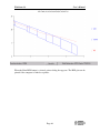
Graphical visualization of the hydraulic grade line for a selected reach
Runoff computations using SCS TR20 method or the Rational method are
provided for
WinStorm is capable of designing and analyzing a system simultaneously when
sizes of features are specified. Additionally, two frequency storms can be run
simultaneously in order to evaluate the performance of a system during different
events, or design a system based on one event and analyze the design under a
different event.
Design Procedure
The input and computation features within WinStorm are designed to follow the typical
progression of urban storm drain design. An understanding of this procedure is beneficial
in developing the systems, describing it within WinStorm, and evaluating the results.
Storm drainage design is an iterative procedure. Design modifications are made
throughout the project development process to arrive at an economical and hydraulically
suitable solution. These modifications often require extensive recalculations of initial
designs and it is this repetitive, yet necessary, step that the true benefits of WinStorm can
be realized.
The following describes the typical design steps of both manual storm drainage design
and the steps recommended for the input of the system into WinStorm:
1. Locate tentative surface collection features (e.g., inlets).
2. Determine contributing drainage areas and define relevant runoff parameters.
3. Compute runoff associated with each drainage area.
Page 3