1
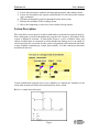
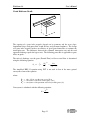
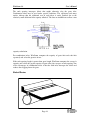
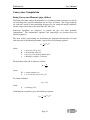
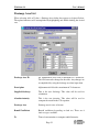
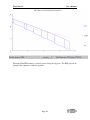
WinStorm 3.0 User’s Manual Introduction WinStorm 3.0 represents the newest release of the WinStorm program by TxDOT. The program itself, while having much of the same look and feel of previous versions, has had its GUI (Graphical User Interface) and hydraulic engine redone to provide for more speed, flexibility, computational capability, and robustness. Also, WinStorm 2.0 limitations regarding installation and data input have been eliminated. New features in v3.0 include: • • • • • • • • Independent computation of runoffs and inlets without being incorporated into a drainage network Allows for the creation of a network with all or only a partially selected number of nodes and links Allows the computation of a system tailwater using normal depth as calculated within an input cross section of the outfall channel Graphic representation of HGL computations Includes the ability to use the SCS TR20 methodology for runoff computations for drainage areas not suitable for the rational method Allows for the conversion of units of measure within an existing project Carryover or bypass flow at an inlet can be defined by a specific discharge or as a percentage of incoming discharge Utilization of standard Windows help files Credits for the development and testing of the program are represented below. Principal Developer: Michael (Mihai) Stan, P.E. (ISD) Contributors: David Stolpa, P.E. (Bridge Division) Amy Ronnfeldt (Bridge Division) Ken Mullin, P.E. (Bridge Division) Stewart Molina, P.E. (Bridge Division) Jim Thompson,P.E (Thompson Professional Group, Houston TX) Review: Houston District, Austin District Fort Worth District, & Dallas District Jim Thompson,P.E (Thompson Professional Group, Houston TX) Support: Judy Skeen, P.E. (ISD) Mary Lou Ralls, P.E. (Bridge Division) Leah Coffman, P.E. (ISD) Page 1 WinStorm 3.0 User’s Manual This Seminar document has been prepared using much of the information and exhibits provided within the Help files of WinStorm 3.0. Acknowledgement is hereby given to the above individuals for their contribution in these regards. Editing and additional information regarding the various computational procedures has been added for further explanation by James F. Thompson, P.E. of Thompson Professional Group, Inc. Page 2 WinStorm 3.0 User’s Manual Overview WinStorm models storm drainage systems using a drainage network comprised of three basic drainage components: 1. Drainage Areas 2. Nodes 3. Links The user describes the components of the system by proceeding through a series of dialogue windows defining each portion of the drainage components. The computational features within WinStorm include the following: • • • • • • • Computing peak discharges associated with the drainage areas Designing and/or analyzing 7 types of storm drain inlets Designing and/or analyzing various conveyance elements (links) including pipes, box culverts, arch-pipes, elliptical pipes, semicircular arches, and ditches Optionally, junction loss computations can be performed at the nodes Graphical visualization of the hydraulic grade line for a selected reach Runoff computations using SCS TR20 method or the Rational method are provided for WinStorm is capable of designing and analyzing a system simultaneously when sizes of features are specified. Additionally, two frequency storms can be run simultaneously in order to evaluate the performance of a system during different events, or design a system based on one event and analyze the design under a different event. Design Procedure The input and computation features within WinStorm are designed to follow the typical progression of urban storm drain design. An understanding of this procedure is beneficial in developing the systems, describing it within WinStorm, and evaluating the results. Storm drainage design is an iterative procedure. Design modifications are made throughout the project development process to arrive at an economical and hydraulically suitable solution. These modifications often require extensive recalculations of initial designs and it is this repetitive, yet necessary, step that the true benefits of WinStorm can be realized. The following describes the typical design steps of both manual storm drainage design and the steps recommended for the input of the system into WinStorm: 1. Locate tentative surface collection features (e.g., inlets). 2. Determine contributing drainage areas and define relevant runoff parameters. 3. Compute runoff associated with each drainage area. Page 3 WinStorm 3.0 User’s Manual 4. Locate and size/analyze each inlet for interception capacity and ponding criteria. 5. Locate and size/analyze the capacity and hydraulics of each conveyance element (pipe or channel). 6. Calculate the hydraulic grade line through the storm drain system. 7. Evaluate the suitability of the resulting system. 8. Revise the components as necessary to meet defined design criteria. System Description The storm drain system must be described sufficiently to perform the requested analysis. Data verification is provided throughout the program, but a layout or description of the system is difficult to ascertain. A storm drain system is a series of ditches, inlets, and enclosed conduits that are connected to collect runoff from drainage area to an outfall. It can be represented by a network of nodes (inlets and junctions) interconnected with links or runs (conduits) terminating at a single point (outfall). It is this connectivity that must be defined by the user. Certain identification protocols have been established to simplify the definition of the storm drain network and define the interconnectivity of the system. Below is a simple network layout: Page 4 WinStorm 3.0 User’s Manual Special Considerations and Limitations • • • • • Pumps are not supported. Other commonly utilized pump routines and other available programs should be utilized and the results integrated with WinStorm. Weirs and orifices must be modeled as equivalent length conduits or as losses applied to junctions (manholes). Multiple incoming links to a node allowed, but only one outgoing link. Only one outfall per network. Diversions and looped systems must be split up and modeled as separate networks. Network Don’ts Networks must be split-up that violate basic computational engine rules. Examples of these scenarios are illustrated below: Page 5 WinStorm 3.0 User’s Manual WinStorm Design Algorithms This section indicates the methods and equations used internally by WinStorm. All of the equations are given in their English form. All metric units are in meters, except area and intensity which are given in hectares and millimeter per hour, respectively. Refer to the metric release of the Hydraulic Volume of the Design Manual for the metric version of these equations and FHWA, Urban Drainage Design Manual, Hydraulic Engineering Circular 22 (Nov. 1996). Runoff Calculation WinStorm models runoff using the Rational Method and the SCS TR-20 Method. The Rational Method is expressed as: Q = CIA where: Q C I A = = = = discharge (cfs) runoff coefficient (cfs⋅hr/ac⋅in) rainfall intensity (in/hr) drainage area (acre) The rainfall intensity is a function of frequency, geography, climatology, and the specific time of concentration for the watershed. The time of concentration describes the longest time it takes for runoff from the most remote part of the watershed to travel to the outfall of the watershed. TxDOT uses the following equation for rainfall intensity: I= b ( t c + d )e where: I = rainfall intensity (in/hr) tc = time of concentration (min) b, d, e = empirical factors that characterize the intensity-duration-frequency (IDF) curves for Texas counties The SCS TR-20 Method is intended for larger contributing drainage areas (generally greater than 200 acres). The basis for computing direct runoff in TR-20 is the equation: Q= ( P − .2 S ) 2 P + .8 S Page 6 WinStorm 3.0 User’s Manual where: Q = actual runoff (inches) S = potential maximum retention (inches) P = rainfall (inches) The potential maximum retention, P, may be expressed as 1.2S. As such, Q = 0 if P is less than or equal to .2S. The value of S is more directly related to the SCS runoff curve number: S= 1000 − 10 CN where: CN = SCS curve number Determination of the SCS curve number is based upon land use, soil type, and other parameters. Most readily available hydrologic reference books have tabulations of various CN values. Another factor included in the SCS TR-20 Method includes antecedent moisture content (AMC) which is a representative value of relative soil moisture valued as 1 for dry, 2 for average, and 3 for wet conditions. The recommended value is 2. If an AMC value of 1 or 3 is chosen, then the CN value is modified accordingly: For AMC = 1; CN1 = 4.2CN / (10 – 0.058CN) For AMC = 3; CN3 = 23CN / (10 + 0.13CN) WinStorm will provide the value of P, or rainfall depth, in inches for 24-hour storms from NWS TP-40 relating to the County and storm event previously selected. Six storm frequencies are supported. Alternately, a value of P may be input by the user directly. The manner in which the storm is distributed is based upon various SCS distribution tables. Again, the user may use many different distributions; however, in Texas for 24hour storms, it is common to use a Type II or III 24-hour distribution. It is recommended that NRCS (formerly the SCS) reference material be obtained to determine what distribution is appropriate for each County. From these data, WinStorm produces a runoff hydrograph using the TR-20 methodology, and a peak discharge is provided in conjunction with the time-to-peak. Gutter Flow Calculations There are two important considerations regarding the gutter approach flow: the ponded width (how far the water extends into the street), and the ponded depth (the depth of water in the gutter). The ponded depth affects the interception rate of on grade inlets. Page 7 WinStorm 3.0 User’s Manual WinStorm calculates the ponded depth and the ponded width by an iterative process using a modified Manning equation for spread flow conditions: Q = (Kg / n)(Sx1.67 )(So0..5)(T2.67) T= y Sx where: Q n Kg Sx So T y = = = = = = = flow rate in gutter (cfs) Manning’s roughness coefficient 0.56 (English) and 0.376 (metric) transverse slope (or cross slope) (ft/ft) longitudinal slope (ft/ft) ponded width (ft) ponded depth (ft) Ponded Width - allowable distance water may accumulate into the roadway. WinStorm reports a warning if gutter flow exceeds this ponding width measured from the curb face [ft or m]. Ponded Depth - allowable depth water may accumulate over a grate or curb at a sag inlet. WinStorm uses this as the default depth to size grates and curbs at sag [ft or m]. When there is a change to the measurement units, the inlet control data must be updated accordingly; otherwise, the system is using the previous inlet control data stored into the database. Inlet Calculations Curb Inlets On-Grade Calculations The computation of on-grade curb opening inlets involves a determination spread or ponded width characteristics, computation of length required for total interception, and consideration of inlet efficiency. Page 8 WinStorm 3.0 User’s Manual T W a Curb Opening Inlet Pavement The hydraulics of Curb Inlets On Grade is derived from HEC-12. The applicable equations are as follows: The length of curb inlet required for total interception using equation: L r = 0.60 Q 0.42 0.3 S 1 n Se 0.6 where: Coefficient 0.6 for English and 0.817 for metric. Lr = length of curb inlet required (ft) Q = flowrate in gutter(cfs) S = longitudinal slope (ft/ft) n = Manning’s roughness coefficient Se = equivalent cross slope (ft/ft) for non depressed inlets The equivalent cross slope (Se) for a depressed curb-opening inlet using equation: Se = S x + a Eo W where: Se SX a W Eo = = = = = equivalent cross slope (ft/ft) cross slope of the road (ft/ft) gutter depression depth (ft) gutter depression width (ft) ratio of depression flow to total flow The ratio of depression flow to total flow is determined using the following equation: W E o = 1 - 1 T 8/ 3 = KW KW + KO The simplified HEC-12 equation using W/T is not used in lieu of the more general conveyance form of the equation. Page 9 WinStorm 3.0 User’s Manual where: Eo = ratio of depression flow to total flow Kw = conveyance of the depressed gutter section (ft3/s) Ko = conveyance of the gutter section beyond the depression (ft3/s) Conveyance is calculated with equation: K= A 5/ 3 n P2 / 3 where: K A n P = = = = conveyance of cross section (cfs) area of cross section (ft2) x 1.486 for English Manning’s roughness coefficient wetted perimeter (ft) Inlet interception capacity is then defined by: Qint ercepted = Qtotal × Efficiency where: Qi = intercepted discharge (cfs) Qt = total inlet discharge (cfs) Efficiency = inlet efficiency defined below Efficiency = 1 − (1 − L 1.8 ) Lr where: Lr = length of curb inlet required for 100% interception (ft) L = length of curb inlet provided (ft) Curb Inlets in a Sag A curb inlet operates as a weir to depths equal to the curb opening height, and as an orifice at depths greater than 1.4 times the opening height. At depths between 1.0 and 1.4 Page 10 WinStorm 3.0 User’s Manual times the opening height, flow is in a transition stage and should be based on the lesser of the weir and orifice capacity computed. The following equation describes the inlet length required for a curb inlet in a sag operating as a weir: L= Q Cw h 1.5 - 1.8 W WinStorm reports the capacity by rearranging the previous equation: Q = C w (L + 1.8*W) h 1.5 where: L Q Cw h W = = = = = length of curb inlet opening (ft) total flow reaching inlet (cfs) weir coefficient = 3.087 (English) and 1.25 (metric) head at inlet opening (allowed ponded depth at inlet not computed) lateral width of depression The equation for capacity of curb openings operating under orifice conditions is the following: Q = Co do L 2 g h where: Q = total flow reaching the inlet (cfs) Co = orifice coefficient = 0.67 do = depth of curb opening. This is the physical depth of the opening including depression depth. L = length of curb opening inlet (ft) g = acceleration due to gravity ft/s2 h = effective head at the center of the orifice throat. Allowed ponded depth – 0.5do The depth of opening (do) will vary with the type of inlet used. The user must input the allowed ponded depth as design criteria for curb inlet in sag calculations. Page 11 WinStorm 3.0 User’s Manual Grate Inlets on Grade The capacity of a grate inlet on-grade depends on its geometry and the cross slope, longitudinal slope, total gutter flow, depth of flow, and pavement roughness. The design of a grate inlet on-grade involves an analysis of given grate dimensions to estimate the interception rate. The difference between the estimated interception rate and the total approach discharge equals the bypass rate. The following procedure is applicable to grate inlets on-grade: The ratio of discharge over the grate (Frontal Flow) to flow to total flow is determined using the following equation: W Eo = 1 - 1 T 8/ 3 = KW KW + KO The simplified HEC-12 equation using W/T is not used in lieu of the more general conveyance form of the equation. where: EO = ratio of flow over the grate to total flow KW = conveyance of the area over the grate (ft3/s) KO = conveyance of the pavement section beyond the grate (cfs) Conveyance is calculated with the following equation: K= A 5/ 3 n P2 / 3 Page 12 WinStorm 3.0 User’s Manual where: K A n P = = = = conveyance of cross section (cfs) area of cross section (ft2) Manning’s roughness coefficient wetted perimeter (ft) The ratio of frontal flow intercepted to total frontal flow: R f = 1 - 0.3 ( V - Vo ) , if V > Vo R f = 1.0, if V < Vo where: Rf = ratio of frontal flow intercepted to total frontal flow V = approach velocity of flow in gutter (ft/s) Vo = minimum velocity that will cause splash over grate (ft/s) The splash over velocity is of the form of Vo = ALN factor 1− N where: Vo = A = N = L = factor is splash over velocity constant for different grate type a power coefficient for different grate type grate length = 1 for English and .3048 for metric Grate Type Coefficient A Coefficient N Parallel 5.74872 0.5038679 Narrow 4.54822 0.5058875 Curved Vane 3.92812 0.5954068 45 Tilt Bar 3.35159 0.5926234 30 Tilt Bar 2.67291 0.7567052 Transverse 3.01181 0.6454720 Reticuline 2.48235 0.7659749 Page 13 WinStorm 3.0 User’s Manual The ratio of side flow intercepted to total side flow: 0.083 zV1.8 R S = 1+ L2.3 ( ) −1 where: 0.083 for metric and 0.15 for English units RS = ratio of side flow intercepted to total flow z = inverse of transverse slope V = approach velocity of flow in gutter (A/s) L = length of grate (ft) The efficiency of grate, Ef, using the equation: [ ] E f = R f E o + R s (1- E o ) The interception capacity of the grate, Qi, using the equation: [ ] Q i = Ef Q = Q R f E o + R s (1- Eo ) The bypass flow rate or carryover is: CO = Q - Q i Grate Inlets in a Sag Sag inlets operate as a weir at low ponding depths and as an orifice at high ponding depths. WinStorm uses an iterative process to calculate the inlet size needed for the existing flow regime. The following equations describe capacity for a grate inlet when operating as a weir and as an orifice, respectively: (weir flow) Q = 3 P y 1 .5 3 for metric and 1.66 for English units (orifice flow) Q = 0 .6 7 A ( 2 g y ) Page 14 0 .5 WinStorm 3.0 User’s Manual where: 0.67 is the Orifice coefficient (metric and English) Q = flow rate (cfs) P = weir perimeter (ft) y = allowed ponded depth on grate (ft) A = clear opening grate area available for flow (ft2) g = acceleration due to gravity (ft/s2) Area or perimeter reduction to account for clogging is not included. The designer should consider the factor when input area and perimeter. WinStorm selects the minimum of weir or orifice flow for the given ponded depth as the controlling discharge. The capacity of a grated inlet in a sag is based on the minimum flow calculated from weir and orifice conditions. The figure below demonstrates the relationship between weir and orifice flow. If Qo is greater than Qw (to the left of the intersection in the figure), then the capacity would be that calculated with the weir equation. If, however, Qo is less than Qw (to the right of the intersection), then the capacity as determined with the orifice equation would be used. Inlet Capacity (Q) Weir (Qw∝h1.5 ) Orifice (Qo ∝h0.5 ) Weir Control Orifice Control Effective Head (h) Combination Inlets Combination inlets consist of a curb opening inlet and a grate inlet placed side-by-side. A combination inlet is sometimes used with a part of curb opening placed upstream of the grate and is called a "sweeper" inlet. Page 15 WinStorm 3.0 User’s Manual The curb opening intercepts debris that might otherwise clog the grate inlet. Combination inlets may be used under special conditions. The experience and many studies indicate that the additional cost of such inlets is rarely justified due to the relatively small additional inlet capacity afforded. The data are insufficient to allow a true capacity calculation. For combination inlets, WinStorm computes the capacity of grate inlet and curb inlet separately and select the greatest of two. If the curb opening length is greater than grate length, WinStorm computes the sweeper's capacity and selects the greater capacity of grate inlet plus sweeper or curb opening. One of the advantages of combination inlets is that the curb inlet intercepts the debris and reduces the clogging factor for grate. Slotted Drains Page 16 WinStorm 3.0 User’s Manual The following equation describes the slotted drain length required for total interception of the flow: (weir flow equation) Lr = 0.706 Q 0.442 S E z 0.849 n 0.384 where: 0.706 for English and 1.04 for metric units. Lr = length of drain required for total interception of flow (ft) Q = flowrate in gutter (cfs) S = gutter longitudinal slope (ft/ft) E = an exponent of the longitudinal slope S. E is a function of S and z as shown. z = reciprocal of transverse slope (ft/ft) n = concrete gutter roughness coefficient (usually about 0.015) The equation for slotted drain is limited to the following ranges of pertinent variables: • • • total discharge ≤ 5.5 cfs longitudinal gutter slope ≤ 0.09 roughness coefficient (n) in the curb and gutter: 0.011 ≤ n ≤ 0.017 The longitudinal slope exponent (E) is determined with the equation: E = 0.207 -19.084S 2 + 2.613S - 0.0001z 2 + 0.007z - 0.049Sz WinStorm calculates carryover for slotted drain as follows: L Q c = 0.918 Q 1 - a Lr 1.769 where: Qc Q La Lr Note: = = = = carryover (cfs) total gutter flow rate (cfs) design length of slotted drain inlet (ft) length of slotted drain inlet required to intercept the total flow (ft) Regarding carryover or bypass flow for any type of inlet on grade that allowed a carryover flow (or bypass), the approach flow to design the inlet is reduced with the amount of carryover. Page 17 WinStorm 3.0 User’s Manual Conveyance Computation Sizing Conveyance Elements (pipe, ditches) WinStorm will either analyze the hydraulics of a described conduit or channel, or size the run according to the specified maximum size and type of element. The design discharge for each run is based on the contributing drainage area, the composite runoff coefficient, and the longest travel time to the upstream node of the run. Numerous algorithms are employed to perform the pipe and ditch hydraulic computations. The fundamental equations and terminology are presented here for reference purposes. The most widely used formula for determining the hydraulic characteristics of storm drain networks is the Manning Formula, expressed by the following equation: V= 1 2/3 1/2 R S n where: V R S n = = = = mean rate of flow (ft/s) the hydraulic radius (ft) the slope of hydraulic gradeline (ft/ft) Manning's roughness coefficient The hydraulic radius (R) is defined as follows: R= A WP where: WP = wetted perimeter (ft) A = cross sectional area of flow (A2) To satisfy continuity, Q = AV where: Q = discharge (m3/s) Combining these equations gives the following equation: Q= 1 2/3 1/2 AR S n Page 18 WinStorm 3.0 User’s Manual Conveyance describes the geometric carrying capacity of a hydraulic conduit and is described by the following equation: K= Q S 1 2 2 1 = AR 3 n Friction Slope is that slope (S) in Manning’s formula required to convey a specified discharge under uniform flow conditions given a depth, roughness, and shape. Under uniform flow, depth and flow area are constant, and the friction slope, actual slope, and energy slope are all equal. After sizing a run, WinStorm calculates the uniform flow depth, the flow area, and the velocity through the conduit. The time of travel to the downstream node is computed by adding the longest travel time to the upstream node and the travel time through the conduit. As the time of travel increases downstream, the design rainfall intensity decreases. It is possible that the cumulative value of CA does not increase in proportion to the inverse of the design rainfall intensity. This is most likely when junctions introduce either no additional drainage area or just a small increase in CA. The result can be a drop in the calculated discharge from upstream to downstream. If this situation occurs, WinStorm will use the higher discharge for design and analysis. Similarly, if the slope of a downstream run is higher than the preceding upstream run such that Manning’s equation would indicate a smaller conduit size downstream, when designing, WinStorm will flag the downstream conduit size such that the user may adjust the size. Hydraulic Grade Line Calculation The methodology employed by WinStorm to compute the water surface profiles though a storm drain network is typical of any open channel water surface procedure. A backwater analysis is performed through the system beginning at the most downstream point (outlet) and progressing upstream to the most remote nodes. WinStorm will compute the hydraulic grade line using gradually varied flow analysis in free surface flow conditions and pressure flow computations under full flow conditions. The resulting hydraulic grade line represents the locus of elevations to which the water would rise if open to atmospheric pressure (e.g., piezometer tubes) along a pipe run and can be used to evaluate the adequacy of the design and identify areas where flooding occurs. Page 19 WinStorm 3.0 User’s Manual Hydraulic = Water Level Grade Line Piezometers The difference in elevation of the water surface in successive pipes usually represents the friction loss in conduits. If the conduit has a slope equal to the friction slope, then the HGL would be parallel to the top of the conduit. If the conduit is placed on a slope less than friction slope, then the HGL gradient would be steeper than conduit slope. If the HGL rises above the top of the conduit (soffit), this would mean that the conduit is under pressure until at some point upstream the HGL is once again at or below the soffit elevation. An analysis is usually necessary to determine the flow characteristics of the outfall channel. The tailwater level occurring in the outfall to the storm drain system will be used in the development of a hydraulic grade line. Hydraulic Gradeline The hydraulic gradeline (HGL) procedure begins at the most downstream node (outlet) and proceeds upstream through each link in the same fashion. A starting HGL at this downstream point elevation must be defined. The procedure for developing the HGL through a link of the network from downstream node to upstream node is as follows: ∆X Energy Gradeline (EGL) ∆E 2 2 v hv 1 = 1 2g hv 2 = v2 2g Hydraulic Gradeline (HGL) Uniform Depth Critical Depth Pipe 2 1 Page 20 WinStorm 3.0 User’s Manual 1. Beginning with the HGL at the downstream node (HGL1), the Energy Gradeline (EGL1) is computed from: EGL = HGL + v2 2g where: v g HGL = = = velocity of flow (ft/s) gravity due to acceleration (32.2 ft/sec2) elevation of hydraulic gradeline Assuming a very small change in the energy and depth (an increment termed ∆y), compute HGL2 from: HGL2 = HGL1+ ∆y. 2. The increment in length, ∆x, corresponding to an assumed increment in depth of water surface profile is describe by the relation: ∆x = (HGL2 - HGL1 ) / (So - Sf ) where: So Sf = = = Slope of the conduit (pipe). Average friction slope for the two adjacent depths under consideration. (Sf1 + Sf2 )/2 Friction slope at depth 1 and 2 is computing using Manning’s equation. This procedure of computing HGL2 and the curve length along the pipe proceeds until one of two things occurs: 1) If the total length of the calculated curve equals or exceeds the length of conduit, then the HGL is the depth in the pipe at the entrance; or 2) If the current depth of the water profile is equal or less than uniform depth, then the HGL is the uniform depth at the entrance. 3. The resulting upstream HGL is subsequently used on the next upstream pipe as its starting downstream HGL. 4. If junction losses are desired, then they are computed prior to progressing upstream and added to the hydraulic grade line. Special Considerations • • If the starting HGL is less than critical depth or uniform depth, then minimum of critical or uniform depth will be assumed. If the HGL converges to equal the uniform depth, the computations proceed to the upstream end at uniform depth. Page 21 WinStorm 3.0 • • • User’s Manual Once the HGL reaches the soffit of the pipe, full flow conditions begin. Hydraulically steep pipes where uniform depth is less than the critical depth are checked with a backwater profile to verify if the resulting upstream HGL drowns out critical depth at the upstream end. If it does, then the backwater profile is accepted. If the backwater curve does not exceed the critical depth, then a forewater profile is generated for this supercritical condition. A forewater profile uses the same procedure as above, but progresses from the upstream end towards the downstream end. It begins at critical depth at the upstream end and converges towards uniform depth as the calculations proceed downstream. The energy grade line computation is not included in WinStorm. Junction Loss Calculation Three junction loss methodologies are discussed: 1. Manhole/junction losses 2. Bend losses 3. Absolute junction losses Manhole/Junction Loss Ht = Kt ( V2 ) 2g where: V = Velocity at the upstream node of conveyance Kt = Loss Coefficient for manhole/junction For manhole losses please reffer to “Modern Sewer Design” Bend Losses Bend losses may be estimated from the equation: 2 H b = Kb V 2g Where Kb can be estimated from the following table. K - Bend Loss Coefficient Degree of Turn at Bend 0.19 15 0.35 30 0.47 45 0.56 60 0.64 75 Page 22 WinStorm 3.0 User’s Manual 0.70 90 Page 23 WinStorm 3.0 User’s Manual Input & Computation Naming Conventions and Input Rules There are a few rules and conventions that apply to identifications of various system components. Below are some basic fundamentals that apply to WinStorm input. • Input Fields or controls labeled with blue text are optional entries. All other input fields and controls are either required or recommended (e.g. for documentation). • Drainage areas and Nodes should have an identification containing a maximum 8 alphanumeric characters. • Project names are limited to 32 characters and Job names to 16 characters. • Project descriptions are limited to 64 characters. Other descriptions are limited to 32 characters. • A drainage area and the respective node to which the discharge is to be applied must have the same identification in order to establish connectivity. For example, drainage area “A-1” flow will enter through inlet “A-1. • Conveyance elements or links (e.g., pipes, boxes, or ditches) are identified by a single numeric identification (e.g., 1, 765, 3), and the respective upstream and downstream nodes are entered in exactly the same manner used to define the inlet/junction or outfall. • Shortcut methods of entering identifications are provided to assist in maintaining the consistency of the ID. WinStorm 3.0 is case sensitive. Two inlets named a1 and A1 would not be considered the same identification; therefore, caution must be used in naming nodes. • All dimensions are in feet for English units and meters for metric units. Exceptions to this are drainage areas, which is measured in acres (English) and hectares (metric), and intensity, which is measured in inches per hour (English) and millimeter per hour (metric). Each input data has a label indicating the measurement units. • All WinStorm project files are binary, with *.stm extension. • WinStorm project files created with an old version can be opened with version 3.0. A dialog box is prompted asking Yes/No for the old *.stm file conversion. Page 24 WinStorm 3.0 User’s Manual Error Checking All input data windows contain an OK, Update, Add, or Cancel button that performs data checking as each element is entered. If the window is closed using the X or Cancel option, then the data will not be checked. It is recommended to select the OK or Update button in order to ensure data is correctly entered. Whenever WinStorm determines an error in the input, a message will be displayed in a message box, specifying the type of error and the field in which the error exists. A typical error message box is displayed below. Page 25 WinStorm 3.0 User’s Manual Starting WinStorm WinStorm is typically run from the Windows Start button or from a shortcut saved to your desktop. Once WinStorm is started, the following screen appears on the desktop. Menu Bar The menu bar consists of six options: Project, Run, Print Reports, Convert, Help, and About. Project Options New This option creates a new WinStorm File. Prior to opening the new file, WinStorm will close the original file. If any changes were previously made to the original file and not saved, a dialog appears prompting to save or ignore the changes. Page 26 WinStorm 3.0 User’s Manual Open This accesses an existing WinStorm project file. If another project is already open, WinStorm will close the original project. If any changes were previously made to the original file and not saved, then a dialog appears prompting to save or ignore the changes. Save This operation saves the current contents to the currently active WinStorm project. Any changes made on the dialog are not recorded in the WinStorm project file unless a File > Save or File > Save As operation is executed. Hence, any power interruption or malfunction will result in loss of data that can be avoided through the judicious use of the File > Save tool. Save As Utilize this option to save the current settings to a new file name. Exit Utilize this option to close and exit the WinStorm application. If the current project has not been saved, a message is displayed. Run Options Run Project This option performs a complete WinStorm computation, including Runoff, Inlets and Network. Compute Runoff Utilize this option to compute runoff only. Compute Inlets Utilize this option to compute inlets only. Print Reports Options (Not Currently Available) Convert Option This option will convert the project measurement unit, from English to Metric and vice versa. Help Opens the WinStorm help file. About Gives information on the Version of WinStorm. Page 27 project WinStorm 3.0 User’s Manual Preferences When the Preferences tab is selected, the dialog dynamically changes to reflect the selection, as depicted below. It is recommended that Project Preferences and Project Information be entered first because data is automatically stored and used for the other inputs. English Units Metric Units Only one unit may be selected by activating the toggle of the desired units. Once selected, the option is utilized to display the associated standard units within each dialog box. Storm frequency Design / Analysis Storm frequency must be indicated by selecting the appropriate toggle button. At least one option is required. If both Design and Analysis frequencies are used, then Design is always the first event computed by the system. Default Values Metric /English units The system is using a list of defaulted values depending on measurement units. These values must be set up at the beginning of the project. If the values are changed for an Page 28 WinStorm 3.0 User’s Manual existing project, then only the new drainage components are using the new input. Option for pipes elevation connection Soffit elevation option (default) or Flowline is available to connect the links at nodes. Default Runoff Coefficients Defaulted values for runoff coefficients. Maximum 6 land use type. Junction Loss computation Option to perform junction loss computation at each upstream node. Several computation options are available. Prefix for ID Option for the prefix for Drainage area ID. Maximum 4 characters Project Information When the Project Information tab is selected, the dialog dynamically changes to reflect the selection, as depicted below. Project Name Alphanumeric field with a maximum of 32 characters. Job Alphanumeric field with a maximum of 16 characters. Description Alphanumeric field with a maximum of 64 characters Page 29 WinStorm 3.0 User’s Manual Outlet ID Any alphanumeric, maximum 8 characters County A Texas county name, to get e, b, d, values for the intensity calculation. e, b, d values Rainfall intensity coefficients based on county and frequency event. This field can be filled by selecting a county name or key in the values. These values and Tc are used to compute the rainfall intensity. Absolute Intensity Intensity to be used in lieu of computed intensity. Using combination of absolute and computed intensity may result in unexpected flow in conduits. Input Tail water Selecting this option, a dialog box with Design tailwater elevation and Analysis tailwater elevation shows up. Compute Tail water Selecting this option, a panel containing required data to compute tailwater shows up. The user may input the out fall channel cross section, up to maximum 50 X,Y points. Manning n value for channel and slope are required. The tailwater is computed based on the channel’s uniform depth, using the fall discharge. No Tail water A text shows up when this option selected. Out fall channel’s Manning n-value and slope Additional Q Data required to compute tail water using uniform depth at the out fall channel. X, Y table Channel cross section X, Y coordinates, up to a maximum 100 points. Browse… This command button will open a dialog box to import an existing text file containing the X, Y values. The values must be stored in the file as X, Y (comma separator). SaveXY This command button will open a dialog box to save the X, Y coordinates from table to a text file. The values will be stored in the file as X, Y (comma separator). Plot This command will plot the X, Y coordinates. This Q and the discharge from the drainage network are used for tailwater computation. Page 30 WinStorm 3.0 User’s Manual Drainage Components When the Drainage Components tab is selected, the dialog dynamically changes to reflect the selection, as depicted below. Drainagee Area List List of drainage area included into project. Node List Node, includes Junctions, Manholes, Inlets. Link List Any valid convey type, pipe, ditch. Add, Edit, Update For each drainage component list, add, edit, and update buttons are available. The same functions can be used by double clicking the line. Page 31 WinStorm 3.0 User’s Manual Drainage Area List When selecting Add or Update, a Drainage Area dialog box appears as depicted below. The update function can be accomplished by highlighting and double clicking the desired row. Drainage Area ID An alphanumeric field with a maximum of 8 characters. The field cannot be changed in the table. Any changes are accomplished by using the drainage area data input form. Description Alphanumeric field with a maximum of 32 characters. Supplied discharge This is the user discharge. This value will be used for calculation. Absolute intensity This is the user intensity. This value will be used to compute the runoff in the CIA equation. Drainage Area Drainage area in acre or hectare. Runoff Coefficient Runoff coefficient depending on land use. There are 6 land use types available. Tc Time of concentration to compute rainfall intensity. Page 32 WinStorm 3.0 User’s Manual Sub area Land Use Definition There are 6 land use types are available with the corresponding C value. SCS TR20 This command will open a Windows for runoff computation using SCS TR20 method. Regression Equations This option is not available Compute Tc If the Compute Tc button is selected, then the dialog widow below appears. After the user enters the C Value, Slope, and Length, click on the Travel Time column to calculate Tc. Land Use The type of land used in the drainage area. Flow regime Type of flow typical for the drainage area. C value Run off coefficient for the overland part of the drainage area. Slope Average water course Slope of the overland flow path Length The length of the flow path for the overland area. Velocity Flow velocity for concentrated flow. Page 33 WinStorm 3.0 User’s Manual Travel Time Travel time for the specific portion of the area. Total Tc Computed travel time. Compute Runoff Using SCS TR20 Method When the SCS TR20 button is selected, then the widow dialog box below appears. Drainage area Drainage area in square miles or square kilometer. Time of concentration The average time of concentration in hour. Curve number SCS curve number, depending on soil characteristics and land use. Antecedent Moisture Condit. A number representing the moisture conditions. 1 Dry, 2 Medium, and 3 Wet. Hydrograph start time Time when hydrograph starts. Hydrograph time increment It is the time interval in which the hydrographs are generated, in fraction of hour. Rainfall depth The rainfall depth for the project area. The number can be computed using the county name and the frequency. Page 34 WinStorm 3.0 User’s Manual Base flow A constant flow from which the hydrograph starts. SCS Rainfall distribution Table Rainfall distribution based on location of watershed. For Texas, two types of rainfall distribution are considered. Type II and Type III. Node List When you select the Add Node or Edit Node icon from the Node List area of the Drainage Components tab, the dialog box below appears. The Edit Node function can also be accomplished by double clicking on the desired row. Node ID Any alphanumeric characters, maximum 8. The ID should be selected from the drainage area list to have connectivity. Select Drainage Area List of the drainage area ID available for connectivity. Description Any maximum 32 characters. Critical or Top Elevation The elevation to flag when the HGL in the node is above this value (usually the lip-of-gutter elevation = Top Elev.). Page 35 WinStorm 3.0 User’s Manual Default Soffit or Flowline The elevation to connect the pipes in the node. Default is soffit elevation Elevation Node Type List List with all available node type. Additional Discharge Additional discharge in the node from outside the system. Junction Loss Calculation Junction Type A list of various junction loss calculations is depicted. Ke Value This field is used for the Ke value, bend angle, or Absolute loss. Approach Gutter on Grade N gutter value Manning “n” value for the gutter. Longitudinal gutter slope The slope along the roadway. Transverse gutter slope The cross slope of the gutter. Transverse gutter width The gutter width, usually the lip of gutter. Page 36 WinStorm 3.0 User’s Manual Max. allowed ponded width. Transverse slope 2 The maximum allowed ponded width for traffic safety. Transverse width 2 Additional cross width. Additional cross slope to compute ponded width (spread). Approach Gutter in Sag (Left and Right) The information required is the same as with the previously described Gutter on Grade plus the following term: Percent Discharge/100 The percent of flow coming from left and right side of the sag inlet. Curb on Grade Curb Length The length of the curb inlet. If null, then the inlet will be designed. Gutter Depression Gutter depression. The ‘a’ value, from 0 to 6 inches. Page 37 WinStorm 3.0 Depression Width User’s Manual The width of depression in front of opening. Usually the lip of gutter. Curb in Sag Curb Length The length of the curb inlet. If null, then the inlet will be designed. Gutter Depression Width The width of depression in front of opening. Usually it is the lip of gutter. Max. Allowed Ponded Depth The maximum allowed ponded depth for inlet calculation. Inlet Opening Height The inlet opening height, including the depression. Grate on Grade Grate Type List of grate type available. Grate Width The grate width. Page 38 WinStorm 3.0 Grate length User’s Manual The grate length. Grate in Sag Grate Type List of grate type available. Grate Area The effective grate area. Bar sizes should not be included. Grate Perimeter The effective grate perimeter. Bar sizes should not be included. The perimeter should be computed for 3 side or 4 side, depending on the grate location. Maximum Ponded Depth The maximum allowed ponded depth for inlet calculation. %Safety Reduction Factor The inlet capacity will be reduced with this percent. Curb and Grate on Grade (combination inlet) Grate Type List of grate type available. Grate Width The effective grate width. Bar sizes should not be included. Page 39 WinStorm 3.0 User’s Manual Grate length The effective grate length. Bar sizes should not be included. Curb Length The length of the curb inlet. Gutter Depression Gutter depression. The ‘a’ value, from 0 to 6 inches. Depression Width The width of depression in front of opening. Usually it is the lip of gutter. Curb and Grate in Sag (combination inlet) Grate Type List of grate type available. Grate Area The effective grate area. Bar sizes should not be included. Grate Perimeter The effective grate perimeter. Bar sizes should not be included. The perimeter should be computed for 3 side or 4 side, depending on the grate location. Maximum Ponded Depth The maximum allowed ponded depth for inlet calculation. Curb Length The length of the curb inlet. Gutter depression Width The width of depression in front of opening. Usually it is the lip of gutter. The maximum allowed ponded depth for inlet calculation. Maximum Allowed Ponded Depth Inlet Opening Height The inlet opening height, including the depression. Page 40 WinStorm 3.0 User’s Manual Slotted Drain Slotted Drain length The length of the slotted drain. Carry Over (or bypass) Carry Over to Inlet The inlet ID to carry over the flow. Allowable Q to Bypass The discharge to be carried over to other inlet. Percent of Q The discharge to be carried over to other inlet, computed as a percentage of the total flow at the inlet. Link List When you select the Add Link or Edit Link icon from the Link List area of the Drainage Components tab, the dialog box below appears. The Edit Link function can also be accomplished by double clicking on the desired row. Page 41 WinStorm 3.0 User’s Manual Run # Run number. If null, will be generated. From Node ID Upstream node ID. Click the text box and select from the list. To Node ID Downstream node ID. Select Node list List with available node to create the network. Soffit or Flowline elevation Soffit or flowline elevation at upstream node. upstrem Soffit or Flowline elevation Soffit or flowline elevation at downstream node. downstream Length The length of the conveyance link. Shape list List with available conveyance shape. Material List List with available material list or Manning “n” value. Compute size option Option to compute the conveyance size. Max. Rise Required Maximum rise required when compute size option Page 42 WinStorm 3.0 User’s Manual selected. Nuber of barrels Number of barrels. Default 1. Type Options include Box, Circular, PipeArch, Arch, Ellipse and Ditch. The desired option is selected from the shape list. Span The span of the selected shape. For ditch span, it is the bottom of the ditch. Rise The rise or the selected shape or the diameter of circular shape pipe. Left / right side slope Side slope horizontal value (horizontal/vertical) for ditches. Bottom Width Options include Box, Circular, PipeArch, Arch, Ellipse and Ditch. The desired option is selected from the shape list. Ditch Depth The depth of ditch is the rise. Span is the ditch bottom. For ditches, the soffit elevation is the water surface in the ditch. When designing ditches, run once to compute the water depth (rise) in the ditch, then adjust the soffit elevation such that the flow line matches the control elevation, usually the ground. Page 43 WinStorm 3.0 User’s Manual Computation When the Computation tab is selected, the dialog box dynamically changes to reflect the selection as depicted below. Compute Options Several computation options are supported within this tab. To select the desired results, simply click the Option. Project Compute Runoff, Inlets and Network. Runoff Runoff computation only. Inlets Runoff and Inlets computation only. Plot HGL Plot Hydraulic Grade Line for a selected reach. View Save Output View the computation text using Notepad windows and Save it. Page 44 WinStorm 3.0 User’s Manual Plotting the HGL When the Plot HGL button is selected, another dialog box appears such that the desired reach may be defined. Reach HGL From node list A list with all available node to create a reach. Reach HGL to node list A list with all available node to create a reach. Set Flow Reach Define the reach based on list selection. Define the path of flow. From: Upstream node reach ID. To: Downstream node reach ID. Plot HGL Pressing the Plot HGL button dynamically changes the dialog as depicted below. The complete path of the flow is shown on the top of the window. Use X top right window button to hide the window. Page 45 WinStorm 3.0 User’s Manual When the Print HGL button is selected, printer dialog box appears. The HGL plot can be printed if the computer is linked to a printer. Page 46