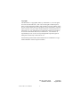
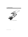
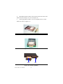
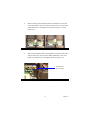
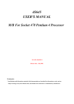
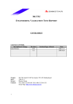
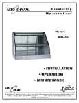
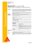
1
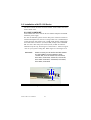
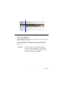
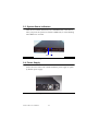
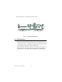
ACP-1120
19" RACKMOUNT 1U HEIGHT
INDUSTRIAL CHASSIS
with IDE DATA MIRRORING
Users Manual
i
Copyright
This document is copyrighted, 2002, by Advantech Co., Ltd. All rights
are reserved. Advantech Co., Ltd. reserves the right to make improvements to the products described in this manual at any time without notice.
No part of this manual may be reproduced, copied, translated or transmitted in any form or by any means without the prior written permission of
Advantech Co., Ltd. Information provided in this manual is intended to
be accurate and reliable. However, Advantech Co., Ltd. assumes no
responsibility for its use, nor for any infringements upon the rights of
third parties which may result from its use.
All brand and product names mentioned herein are trademarks or registered trademarks of their respective holders.
Part No. 2002112000
Printed in Taiwan
ACP-1120 User’s Manual
ii
1st Edition
August 2002
Contents
Chapter
1 General Information ........................................2
1.1
1.2
1.3
1.4
1.5
1.6
Introduction ....................................................................... 2
General Specifications....................................................... 2
Passive Backplane Options ............................................... 3
Power Supply Options....................................................... 3
System Regulation.............................................................4
Dimensions........................................................................ 5
1.7
Exploded Diagram............................................................. 6
Figure 1.1:Dimensions.................................................... 5
Figure 1.2:Exploded Diagram......................................... 6
Chapter
2 System Setup.....................................................8
2.1
System Installation ............................................................ 8
2.1.1
2.1.2
2.1.3
2.1.4
2.2
Removing the top cover.................................................. 8
Chassis Front and Rear Sections..................................... 8
Figure 2.1:Front Chassis ................................................. 8
Figure 2.2:Rear Chassis .................................................. 9
Drive Bay Installation..................................................... 9
Figure 2.3:Slim-type CD-ROM and 3.5" FDD............. 10
Figure 2.4:Location of driver bay ................................. 10
Figure 2.5:HDD Holder ................................................ 11
Figure 2.6:Location of 3.5" HDD ................................. 11
Figure 2.7:IDE H/S Drawer .......................................... 12
Figure 2.8:H/S Drawer w/HDD .................................... 12
Figure 2.9:Location of IDE 0/1..................................... 12
CPU Card and Add-On Cards Installation.................... 13
Figure 2.10:................................................................... 13
Figure 2.11:................................................................... 13
Figure 2.13:PCI and SBC card installation................... 14
Figure 2.14:PCI and SBC cardholder ........................... 14
Figure 2.12:................................................................... 14
Figure 2.15:Location of SBC and PCI card holder....... 15
Figure 2.16:Fixed SBC by SBC Holder........................ 15
Installation of ACP-1120 Series...................................... 16
2.2.1
2.2.2
ACP-1120P2-20Z ......................................................... 16
Figure 2.17:SBC Side of BP ......................................... 16
ACP-1120X2-20Z......................................................... 17
Figure 2.18:PCI Side of BP .......................................... 17
2.3
System Status Indicators ................................................. 18
2.4
Power Supply .................................................................. 18
Figure 2.19:LED Indicator............................................ 18
1
Figure 2.20:AC 110/240V P/S...................................... 18
Figure 2.21:DC48V P/S................................................ 19
2.5
Cooling Fan ..................................................................... 19
Figure 2.22:................................................................... 20
Figure 2.23:................................................................... 20
Chapter
3 IDE Data Mirroring Board ...........................20
3.1
3.2
IDE HDD Installation...................................................... 20
Functions and Features.................................................... 21
3.3
LED Indicator.................................................................. 22
3.4
Compatibility List............................................................24
Figure 3.1:IDE RAID BD Layout................................. 22
Figure 3.2:LED Indicator of HDD Drawer................... 23
Appendix A Backplane Layout...........................................26
Appendix B Safety Instructions .........................................28
B.1
Safety Instructions........................................................... 28
ACP-1120 User’s Manual
2
CHAPTER
1
General Information
1
Chapter 1
Chapter 1 General Information
1.1 Introduction
APC-1120 is a rack-optimized server that offers superior performance
and scalability for customers who want to growth their business without
increasing their data center space. It is an ideal server for infrastructure
and Web-hosting applications with up to two-way processors, dual hotswappable IDE hard rivers for data mirroring backup and two PCI fulllength 64-bit I/O slot. The best streamline & efficiency cooling system
design to minimize the system down time and the low total cost of ownership of ACP-1120, which provides the best choice for fast-growing Internet service providers and corporate enterprise customers use the ACP1120 as e-server platforms for their internet/intranet or file and print
server. The ultra-thin server with 1U form factor delivers rack space optimization without sacrificing performance, expandability, serviceability,
or manageability
1.2 General Specifications
General
• Construction: Heavy duty steel chassis
• Drive bay: Front accessed one slim CD-ROM & 3.5" driver bay; dual
hot-swap 3.5" disk driver bay and one 3.5" internal driver.
• Cooling system: Three easy-to-replace 10CFM cooling fan inside
chassis and one easy-to-replace 10CFM cooling fan on rear of chassis.
• Controls: Power momentary switch (ATX switch), reset switch which
are behind the door
• System LED Indicator: Power: Single-color LED for system power,
HDD: Single-color LED (orange) for HDD activity, both are on front
bezel of door
• Rear panel: D-SUB 9-pin bracket
• Paint Color: Pantone 4C 2X Black, textured
• Operating temperature: 0°C ~ +40°C (32°F ~ 104°F)
• Storage temperature: -40° to +60°C (-40° to +140°F)
• Relative Humidity: 10 ~ 95%@40°C, non-condensing
• Vibration: 5Hz ~ 500Hz, 0.5Grms (Operating), 2G (non-operating)
ACP-1120 User’s Manual
2
• Shock (operating): 30 G with 11m Sec duration, 1/2 sine wave
• Acoustic Noise: Less than 52 dB sound pressure at +5°C to +28°C
(+41°F to +82°F)
• Altitude: 0 to 3048m (0 to 10,000 ft)
• Slide rails: Optional
• Dimensions: 482mm(W) x 44mm(H) x 629mm(D) or 19"(W) x
1.7"(H) x 24.76"(D)
• Weight: 14kg. (30.8lbs.)
• Safety: CE compliant, UL/cUL approved
1.3 Passive Backplane Options
Backplane models (refer to appendix for details)
• PCA-6103P2V: CPU/ 2-PCI
• PCA-6103P2VX: CPU/ 2-PCI(64-bit)
1.4 Power Supply Options
Model name
Specification
Watt
Input
Output
Mini-load
Safety
MTBF
1757920000
(ATX,PFC)
200
W
100 ~
240Vac(
Fullrange)
+5V@ 16A
+3.3V@14A
+12V@9A
[email protected]
[email protected],
[email protected]
+5V@2A
+12V@1A
[email protected]
[email protected]
+3.3V@1A
[email protected]
ULCE
EN61000
-3-2
Class
DTUV
100,000
hours
@25°C
1757918000
(ATX)
180
W
-40VDC
~
-56VDC
+5V@ 20A
+3.3V@12A
+12V@7A
-12V@1A
[email protected]
[email protected]
+5V@2A
+12V@1A
[email protected]
[email protected]
+3.3V@1A
[email protected]
ULTUV
100,000
hours
@25°C
3
Chapter 1
1.5 System Regulation
Ordering Information
Model name
With Power Supply
With Backplane
Regulation
ACP-1000P2-20Z
With 200W ATX PFC
Power Supply
With PCA-6103P2V(Two 32bit PCI slot for expansion)
UL,cUL,CE
ACP-1000X2-20Z
With 200W ATX PFC
Power Supply
With PCA-6103P2XVFor
PCA-6278, PCA-6183
only(Two 64-bit PCI slot for
expansion)
UL,cUL,CE
ACP-1120P2-18D
With 180W DC48V
Power Supply
With PCA-6103P2V(Two 32bit PCI slot for expansion)
UL,cUL,CE
ACP-1120X2-18D
With 180W DC48V
Power Supply
With PCA-6103P2VX For
PCA-6183, PCA-6278
only(Two 64-bit PCI slot for
expansion)
UL,cUL,CE
Optional Device
Ordering P/N
Descriptions
SCD-ROM
Slim-type CD-ROM Kit
9684000014
3.5" FDD with Black Bezel
9689000535
1U Slide Rail for ACP-1000
1759209201
Low profile CPU cooler for ACP-1000
1759252100
Low profile P4 CPU cooler for ACP-1000 series
P-DI256GBSNECD1
Low profile 256MB DRAM for ACP-1000
ACP-1120 User’s Manual
4
1.6 Dimensions
Figure 1.1: Dimensions
5
Chapter 1
1.7 Exploded Diagram
Figure 1.2: Exploded Diagram
ACP-1120 User’s Manual
6
CHAPTER
2
System Setup
7
Chapter 2
Chapter 2 System Setup
2.1 System Installation
WARNING:
Before starting the installation process, be sure
to shut down all power from the chassis. Do this
by turning off the power switch, and unplugging
the power cord from the power outlet. When in
doubt, consult with an experienced technician.
2.1.1 Removing the top cover
The first installation step is removing the chassis cover. You will need a
Phillips screwdriver. Top cover is fixed to the chassis with five (6) M3
sink-flat screws. To remove the top covers:
1.
Detach the six sink-flat screws on the top of chassis.
2.
Lift off the top cover.
2.1.2 Chassis Front and Rear Sections
The control switches located behind the door are used for system power
switch and system reset. On the right side of system power switch, there
are IDE 0 and IDE 1 hot-swappable HDD drawer. On the top of IDE 0,
there are Power LED and HDD LED. Refer the Figure 2-1..
IDE 0
Figure 2.1: Front Chassis
ACP-1120 User’s Manual
8
IDE 1
Momentary Switch: Use this switch and by way of ATX(PS_ON) function to turn on system power. Please use system shutdown to turn off system power automatic or press momentary switch for a while to turn off
system power
System Reset Switch: Press this switch to reinitialize the system. This is
the same as the hardware reset button. The rear section of chassis
includes: 3-slot I/O bracket, and a DB-9 bracket. Refer the Figure 2-2.
Figure 2.2: Rear Chassis
2.1.3 Drive Bay Installation
The ACP-1120 standard drive bay can hold one slim-type CD-ROM, two
3.5" driver bay and dual hot-swappable 3.5" HDD drawer.
Installation disk drives
a.
Remove the Top Front Cover
b.
Undo the three screws fixing the standard drive bay.
c.
Lift off the standard drive bay.
d.
Install slim-type CD-ROM and 3.5" driver as Figure 2-3
e.
Insert the drives into their proper locations as Figure 2-4 and secure
them with the screws provided.
f.
Connect the disk drive power and signal cables.
9
Chapter 2
.
Figure 2.3: Slim-type CD-ROM and 3.5" FDD
Figure 2.4: Location of driver bay
g.
Lift off the internal 3.5" HDD holder by undo the four screws.
h.
Install 3.5" HDD into HDD holder. See Figure 2-5
i.
Insert the 3.5" HDD holder with HDD into their proper location.
See Figure 2-6
j.
Connect the disk driver power and signal cables
ACP-1120 User’s Manual
10
Figure 2.5: HDD Holder
Figure 2.6: Location of 3.5" HDD
k.
Take out two hot-swappable drawers from front chassis.
l.
For each H/S drawer, undo two screws to release HDD interface
board from rear of drawer and install 3.5" IDE HDD into H/S drawer as
Figure 2-7.
11
Chapter 2
m. Back HDD interface board to the original location and connect with
HDD well, then fixed by two screws as Figure 2-8.
n.
Please plug IDE 0 and IDE 1 two hot-swappable drawers within
HDD into chassis as Figure 2-9.
Figure 2.7: IDE H/S Drawer
Figure 2.8: H/S Drawer w/HDD
IDE 0
IDE 1
Figure 2.9: Location of IDE 0/1
ACP-1120 User’s Manual
12
2.1.4 CPU Card and Add-On Cards Installation
Regarding ACP-1120 is 1 U super slim chassis, it will be difficult to
install slot board computers and other PCI add-on boards if you do not
follow the below installation guide.
1.
Remove the chassis cover.
2.
By detaching two screws from rear chassis showed on Figure 2-10
and detaching one screw inside chassis showed on Figure 2-11 to
take out the backplane holder with backplane showed as Figure 212.
Figure 2.10:
Figure 2.11:
13
Chapter 2
Figure 2.12:
3.
Insert the CPU card from the right-hand side and insert PCI add-on
card from the left-hand side into the vacant slot as Figure 2-13.
Please don't forget to align and fix the screw to tight the card to a
fixed position.
Figure 2.13: PCI and SBC card installation
Figure 2.14: PCI and SBC cardholder
ACP-1120 User’s Manual
14
4.
Before returning the backplane holder with backplane, with CPU
card or PCI add-on cards to the chassis, please move away the CPU
card holder or PCI card holder first, showed as Figure 2-14 and
Figure 2-15.
Figure 2.15: Location of SBC and PCI card holder
5.
Return the backplane holder, with backplane, with CPU card or PCI
add-on cards to the chassis and use SBC cardholder or PCI cardholder to fix SBC or PCI card tightly. Refer the Figure 2-16.
SBC Holder with
rubber to fix SBC
Figure 2.16: Fixed SBC by SBC Holder
15
Chapter 2
2.2 Installation of ACP-1120 Series
The ACP-1120 can be of the two basic models, ACP-1120P2 series and
ACP-1120X2 series.
2.2.1 ACP-1120P2-20Z
ACP-1000P2-20Z comes with the PCA-6103P2V backplane and 200W
ATX PFC power supply.
For ACP-1120P2-20Z, please connect ATX power connector with PCA6103P2V backplane first, then use a orange-white wire (1700030500) to
connect between ATX feature-CN1 (5VSB_GND_PSON) of Backplane
and "ATX feature connector" (CN20) of SBC, finally connect POWER
SW wire with "ATX soft power switch"(CN21) of SBC to finish the
installation. By the way, don't forget to connect FAN1 ~ FAN5 to support
+12V for your system cooling fans. Refer Figure 2-17 and Figure 2-18.
WARNING:
Please consult your AE before the SBC installation. Most SBCs can be installed to ACP1120P2-20Z, such as PCA-6178, PCA-6276,
PCA-6277, PCA-6180, PCA-6181, PCA-6184,
PCA-6186. PCA-6001, PCA-6002, PCA-6003,
PCA-6004, PCA-6005
Fan 3
Fan 4
CN 1
ATX Connector
Figure 2.17: SBC Side of BP
ACP-1120 User’s Manual
16
Fan 1
Fan 2
Figure 2.18: PCI Side of BP
2.2.2 ACP-1120X2-20Z
ACP-1120X2-20Z comes with the PCA-6103P2VX 64-bit backplane and
200W ATX PFC power supply.
For ACP-1120X2-20Z, the cabling connection are complete same as
ACP-1120P2-20Z but ACP-1120X2-20Z is available for 64-bit CPU
cards only.
WARNING:
Please consult your your technical engineer
first. For 64-bit PCI backplane, some of SBC
could be installed to ACP-1120X2-20Z, such as
PCA-6278, PCA-6183, PCA-6185.
17
Chapter 2
2.3 System Status Indicators
There are two LED on front bezel, one is POWER LED, it will turn on
when you power the system on, another is HDD LED, it will be blinking
when HDD to be accessed
Power
HDD
Figure 2.19: LED Indicator
2.4 Power Supply
ACP-1120 series comes with a 200W ATX PFC power supply or option
by DC48V power supply.
Figure 2.20: AC 110/240V P/S
ACP-1120 User’s Manual
18
Figure 2.21: DC48V P/S
2.5 Cooling Fan
There are four (4) cooling fans located inside the chassis. The cooling
fans are easy maintenance and provide adequate cooling to the system by
blowing air inward. There are three cooling fans located on the middle of
19
Chapter 2
chassis to get the fresh air; one cooling fan is located on the rear of chassis to draw the thermal out. Refer the Figure 2-22 and Figure 2-23
Figure 2.22:
Figure 2.23:
ACP-1120 User’s Manual
20
CHAPTER
3
IDE Data Mirroring
Board
19
Chapter 3
Chapter 3 IDE Data Mirroring Board
3.1 IDE HDD Installation
Warning:
Before starting the IDE HDDs installation process, please read the descriptions bellow in
detail. When in doubt, consult with an experienced technician.
• When Booting: The LED of both IDE 0 and IDE 1 will blink once and
Buzzer of IDE Data Mirroring Board will alert once. Now IDE RAID
level 1 data mirror function already operates. This will synchronize the
two hard disk drives, protecting your operating system and important
data on time.
• Data mirroring: Recommend using two new hard disks with same
brand and model for data mirroring
• Hard Disk Setup: Please setup both of two hard disk drivers in "Master Mode". Normally the default factory-setting mode is " Cable
Select".
• System Installation: If you want to install operating system into here,
recommend user may install operating system on one hard disk first,
and then copy to another one by using "Auto Rebuild". ACP-1120 system is with mobile IDE drawer "0" and inside within one IDE hard disk
(IDE 0), then user could install operating system by way of slim type
CD-ROM. User could plug in mobile IDE drawer "1" which is within
one IDE hard disk (IDE 1) inside after finishing the operating system
installation. Now IDE data mirror board will auto rebuild after IDE 1
plug in well.
• Install New HDD: If you want to use a new HDD to replace the original HDD for some reason, the new HDD's capacity must be equal or
larger than the original one's.
• Using FDISK: If you want to reinstall OS in two used hard disk drivers
synchronously, please first FDISK to delete partitions of the two hard
disk driver respectively
• One HDD Failure: The buzzer will alert, you may know which hard
disk driver is failure by the status LED of IDE 0 and IDE 1.
ACP-1120 User’s Manual
20
• Auto-Rebuild: When one hard disk driver is failure, user may replace
it with a good one. The system will go into " Auto-Rebuild" mode
when IDE data mirroring board detecting a new hard disk driver plugging in well and you may know the system in "Auto-Rebuild" model
from the status LED of IDE 0 and IDE 1.
3.2 Functions and Features
• Data mirroring: RAID Level 1. Backup data from one hard disk driver
to another one automatically.
• Plug and Play: No need to install any device driver
• OS Independence: Supports all operating system
• Auto Rebuild: Under system execution, if one hard disk driver is
replaced, IDE data mirroring board will rebuild data to new hard disk
right away.
• Hot-Swap: When one HDD failure, you could remove out the failure
HDD without system power off or shutdown.
• High Capacity: Hard disk driver capacity is limited in 128G Bytes for
S/W version 1.0
• System Indicators: Show system status by status LED of IDE 0 and IDE
1
• Hard Disk Compatibility: Supports most of all major brand's IDE hard
disk drivers, refer compatibility list
• Multi-boot System: Support System Commander, IBM OS/2 Boot
Manager,°Ketc.
• RAID Manager: Optional software that operates with RAID system and
allow user to monitor and remote monitor the status of RAID system
• JP3 Pin Definition:
Pin 1-2: Short=Master (Default) Open= Slave
Pin 3-4: Short=Mirror (Default) Open= No Function
Pin 5-6: Short=Enable Buzzer (Default) Open= Disable Buzzer
Pin 7-8: Short=Upgrade F/W Mode Open= Normal Mode (Default)
21
Chapter 3
Refer the Figure 3-1 to find out the jumper location.
Figure 3.1: IDE RAID BD Layout
3.3 LED Indicator
• Power LED: IDE 0 and IDE 1 both are with a "Power LED" on front
bezel, refer the figure 3-2. When system is power on and "Power LED"
is turning off if there is no HDD inside. When system is power on and
" Power LED" is turning on if there is HDD inside.
• Status LED: IDE 0 and IDE 1 both are with a "Status LED" which is on
the top of Power LED. The Status LED is BLUE color blinking for
HDD data access. The Status LED turns RED color for HDD failure.
ACP-1120 User’s Manual
22
The Status LED turns PURPLE (BLUE+RED) blinking for system
data is under construction (rebuilt). Find the location from Figure 3-2.
Power LED
Status LED
Power LED
IDE 0
Figure 3.2: LED Indicator of HDD Drawer
23
Chapter 3
3.4 Compatibility List
Fujitsu
Model
Size (GB)
Model
Size (GB)
(1) MPG3307AT
30.7
(3) MPD3064AT
6.4
(2) MPD3091AH
9.1
(4) MPD3043AT
4.3
Model
Size (GB)
Model
Size (GB)
(1) LM20500AT
20.5
(6) KA9100A
9.1
(2) AS20000AT
20.0
(7) CR8400A
8.4
(3) LM15000AT
15.0
(8) CX6400A
6.4
(4) CX10200A
10.2
(9) CR6400A
6.4
(5) EL10A013
10.0
Quantum
Seagate
Model
Size (GB)
Model
Size (GB)
(1) ST340824A
40.0
(4) ST328040A
28.0
(2) ST330620A
30.0
(5) ST320414A
20.0
(3) ST330631A
30.0
(6) ST315320A
15.0
Model
Size (GB)
Model
Size (GB)
(1) MPG3307AT
30.7
(3) MPD3064AT
6.4
(2) MPD3091AH
9.1
(4) MPD3043AT
4.3
Fujitsu
ACP-1120 User’s Manual
24
IBM
Model
Size (GB)
Model
Size (GB)
(1) DTLA-307075
76.8
(7) DJNA-371800
18.0
(2) DTLA-307045
46.0
(8) DJNA-371350
13.5
(3) DPTA-353750
37.5
(9) DJNA-371010
10.1
(4) DTLA-307030
30.0
(10) DJNA-351010
10.1
(5) DJNA-372200
22.0
(11) DJNA-370910
9.1
(6) DTLA-307030
20.0
(12) DJNA-350640
6.4
Samsung
Model
Size (GB)
(1) SV2042N
20.0
25
Chapter 3
ACP-1120 User’s Manual
26
Appendix
A
Backplane Layout
25
Chapter A
Appendix A Backplane Layout
PCA-6103P2V
PCA-6103P2VX
ACP-1120 User’s Manual
26
Appendix
B
Safety Instructions
27
Chapter B
Appendix B Safety Instructions
B.1 Safety Instructions
1. Read these safety instructions carefully.
2. Keep this User's Manual for later reference.
3. Disconnect this equipment from any AC outlet before cleaning. Use a damp
cloth. Do not use liquid or spray detergents for cleaning.
4. For plug-in equipment, the power outlet socket must be located near the
equipment and must be easily accessible.
5. Keep this equipment away from humidity.
6. Put this equipment on a reliable surface during installation. Dropping it or letting it fall may cause damage.
7. The openings on the enclosure are for air convection. Protect the equipment
from overheating. DO NOT COVER THE OPENINGS.
8. Make sure the voltage of the power source is correct before connecting the
equipment to the power outlet.
9. Position the power cord so that people cannot step on it. Do not place anything
over the power cord.
10. All cautions and warnings on the equipment should be noted.
11. If the equipment is not used for a long time, disconnect it from the power
source to avoid damage by transient overvoltage.
12. Never pour any liquid into an opening. This may cause fire or electrical shock.
13. Never open the equipment. For safety reasons, the equipment should be
opened only by qualified service personnel.
14. If one of the following situations arises, get the equipment checked by service
personnel:
a. The power cord or plug is damaged.
b. Liquid has penetrated into the equipment.
c. The equipment has been exposed to moisture.
d. The equipment does not work well, or you cannot get it to work according
to the user's manual.
e. The equipment has been dropped and damaged.
f. The equipment has obvious signs of breakage.
15. DO NOT LEAVE THIS EQUIPMENT IN AN ENVIRONMENT WHERE
THE STORAGE TEMPERATURE MAY GO BELOW -20° C (-4° F) OR
ABOVE 60° C (140° F). THIS COULD DAMAGE THE EQUIPMENT. THE
EQUIPMENT SHOULD BE IN A CONTROLLED ENVIRONMENT.
Th sound pressure level at the operator’s position according to IEC 704-1:1982 is
no more than 70dB(A).
DISCLAIMER: This set of instructions is given according to IEC 704-1. Advantech disclaims all responsibility for the accuracy of any statements contained
herein.
ACP-1120 User’s Manual
28
16. Any insulation on conductors inside EQUIPMENT which connect ACCESSIBLE METAL PARTS or other PROTECTIVELY EARTHED parts with a protective functio to the PROTECTIVE EARTH TERMINAL shall be identified
by the colrs green and yellow at lease at the termination of the conductors.
17. CAUTION: The computer is provided with a Battery-powered Real-Time
Clock Circuit. There is a danger of explosion if battery is incorrectly
replaced. Replace only with same or equivalent typed recommended by the
manufacturer. Discard use batteries according to the manufacturer’s instructions.
18. The computer is provided with appropriate safety standards including lec
60826.
CLASS 1 LASER PRODUCT
KLASSE 1 LASER PRODUCT
19 Install the computer. Before your begin make sure the Green/Yellow wire reliable connection between metal part of computer and earthing of final system.
29
Chapter B
ACP-1120 User’s Manual
30