1
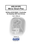
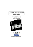
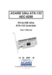
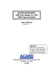
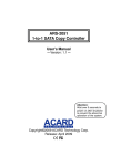
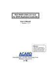
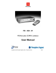
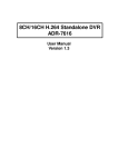
ARS-2012PEL
Mirror Smart Plus
User’s Manual
Version: 1.0
Copyright © 2002 ACARD Technology Corp.
Release: August 2002
Copyright and Trademarks
The information of the products in this manual is subject to change without
prior notice and does not represent a commitment on the part of the vendor,
who assumes no liability or responsibility for any errors that may appear in
this manual.
ACARD and SCSIDE are the trademarks of ACARD Technology Corp. IBM
is the trademark of International Business Machine Corporation. Microsoft
and the Windows Logo are the registered trademarks, and Windows is the
trademark of Microsoft Corporation. All brands and trademarks are the properties of their respective owners.
This manual contains materials protected under International Copyright Conventions. All rights reserved. No part of this manual may be reproduced in
any form or by any means, electronic or mechanical, including photocopying, without the written permission of the manufacturer and the author. All
inquiries should be addressed to ACARD Technology Corp.
Table of Contents
Chapter 1 About SCSIDE .................................. 4
1.1 Revolutionary Technology ..................................... 4
1.2 SCSIDE® Design .................................................... 5
Chapter 2 Introduction ...................................... 6
2.1
2.2
2.3
2.4
2.5
2.6
Overview .................................................................. 6
Features .................................................................... 6
Quick Start ............................................................... 7
Package .................................................................... 7
Specifications .......................................................... 7
Compatibility ........................................................... 8
Chapter 3 The Control Panel .......................... 10
Chapter 4 Hardware Installation ..................... 13
4.1 Installing a SCSI Adapter ..................................... 13
4.2 Installing ARS-2012PEL ....................................... 13
4.2.1 Preparation .............................................................................13
4.2.2 IDE Hard Drive Connection ................................................14
4.2.3 External Power Connection ...............................................16
4.2.4 External Cable Connection ................................................17
4.2.5 DIP Switch Setting ................................................................18
Chapter 5 Troubleshooting ............................. 21
5.1 Basic Troubleshooting ......................................... 21
5.2 Advanced Troubleshooting ................................. 22
5.2.1 Verify the SCSI Adapter .......................................................22
5.2.2 Verify ARS-2012PEL .............................................................25
Appendix 1 SCSI Adapter Compatibility........ 27
Appendix 2 Mirror Smart Utility...................... 28
ARS-2012PEL User’s Manual
Chapter 1 About SCSIDE
1.1 Revolutionary Technology
SCSIDE® is a revolutionary technology developed by ACARD Technology Corp. It
can not only transform IDE data into SCSI type, but also save the expenditures.
Through this technology any cheap IDE device can have high-performance SCSI
applications. The following examples are simply a little portion of SCSIDE®
applications.
1. To transform an IDE hard disk into an external SCSI one for notebook and desktop
PC users to back up data.
2. To transform a 50X IDE CD-ROM into a 50X LVD SCSI one. It is an unprecedented
technology.
3. To transform your favorite IDE DVD-ROM into LVD SCSI one.
4. To daisy chain multiple SCSIDE® DVD-ROMs to create a DVD-ROM server.
5. To transform a DMA33/66/100/133 hard drive of 5400rpm or 7200rpm into
an LVD SCSI one for PC workstations, servers and Unix workstations, servers.
The basic structure of SCSIDE® is a “RAID On Chip” which highly integrates multiple
CPUs. This ROC design is resulting from ACARD’s years of experiences in the
design of IDE, SCSI and RISC CPU chips. The block diagram on the next page
shows that ROC has multiple CPUs. Its ROM, RAM, DMA controllers and external
ROM interface can be used as the firmware update of flash ROM. ACARD has a
perfect firmware technology, too. It makes the transformation of IDE to SCSI really
“plug and play”. The firmware has been tested on almost all brands of IDE DMA33/
66/100/133 HDDs, ATAPI CD-ROMs, DVD-ROMs. Whether your IDE device is an
ATA hard drive, CD-ROM, CD-RW or DVD-ROM, you can all plug it and enjoy the
advantages of SCSI. With the intelligent firmware design, you don’t need to install a
4
ARS-2012PEL User’s Manual
driver into the operating system so as to use SCSIDE® products. In the operating
system it is just like a SCSI device.
Figure 1-1
1.2 SCSIDE® Design
The objectives of SCSIDE® design are given as follows:
1. Save the expenses of SCSI by using an inexpensive IDE device.
2. Create applicaions like 50X SCSI CD-ROM and high speed SCSI DVD-ROM.
3. Apply ”plug and play” to the transformation of IDE device to SCSI one. It is not
necessary to install a driver.
We welcome you to be a new member of SCSIDE® and have a good time.
5
ARS-2012PEL User’s Manual
Chapter 2 Introduction
2.1 Overview
ARS-2012PEL LVD (Low Voltage Differential) SCSI RAID 1 System is particularly
designed for disk mirroring. It consists of two hard disk drives for duplicating data as
Figure 2-1 shows. However, the computer still regards them as a single drive. Via
the built-in microcontroller, ARS-2012PEL makes high-level applications more flexible
and stable. It can easily transform any IDE device into an LVD SCSI one.
LVD SCSI-to-SCSI RAID 1 Controller
D0
D1
D0
D1
Dn
Dn
Identical data is recorded on both HDDs
Figure 2-1
2.2 Features
ARS-2012PEL Mirror Smart Plus has the following features.
n
n
n
n
n
n
n
n
Is a standalone LVD SCSI-to-SCSI RAID 1 controller.
Has an auto-eject handle on the cabinet to eject a failed hard drive.
Has aluminum & steel heat sink frame design.
Has an alarm-off resetting button.
Supports “Big Drives” technology.
Supports cross-platform operation.
Supports HOT SWAP.
Supports multitasking.
6
ARS-2012PEL User’s Manual
n
n
Has lower CPU system loading.
Has a built-in SOC SCSIDE® engine.
2.3 Quick Start
Please follow the 7 steps given below to use ARS-2012PEL Mirror Smart Plus.
Step 1: Make sure that all cables are connected well to your PC.
Step 2: Take the cabinet out of the Mirror Smart Plus.
Step 3: Put a hard drive into the cabinet and connect it with the internal cable.
Step 4: Replace the cabinet to the Mirror Smart Plus.
Step 5: Make sure that the auto-eject handle on the cabinet is closed.
Step 6: Power on the system.
Step 7: Use the Mirror Smart Plus as a new hard drive device.
2.4 Package
Upon receiving the package of ARS-2012PEL unpack it and check its contents.
n
n
n
n
n
n
ARS-2012PEL
A CD containing the driver and the Mirror Smart Utility
A user’s manual
LVD cable (optional)
LVD terminator (optional)
AEC-67160 Ultra 160 SCSI Adapter (optional)
**Please refer to Appendix 2 for the Mirror Smart Utility.
2.5 Specifications
1.ARS-2012PEL Mirror Smart Plus
Materials
Aluminum & steel base, cover, ABS shell and front panel
7
ARS-2012PEL User’s Manual
Temperature
0°C to 70°C for operation
-20°C to 85°C for storage
Humidity
15% to 90%
Dimension
Length: 28cm
Width: 18cm
Height: 16cm
2.AEC-67160 SCSI Adapter (optional)
Please refer to the user’s manual of AEC-67160 SCSI Adapter.
2.6 Compatibility
ARS-2012PEL is especially designed for DMA hard drives. It fully supports the
following brands of DMA33/66/100/133 hard drives. Besides, it is compatible with
various kinds of SCSI cards, and can operate well in Mac or Linux.
n
n
n
n
n
n
IBM HDD
MAXTOR HDD
QUANTUM HDD
SEAGATE HDD
Fujitsu HDD
WESTERN DIGITAL HDD
For details please see the next page.
8
ARS-2012PEL User’s Manual
IBM HDD
DTLA series, DPTA series, DTTA series, DJNA series, 60 GXP, 75 GXP.
MAXTOR HDD
54098U8, 52049U4, 91366U4, 94098U8, 91020U3, 98196H8, 5T020H2.
QUANTUM HDD
FireBall LM series, LC series, LB series, LD series.
FireBall KX series, KA series.
FireBall CX series, CR series, EX series.
FireBall EL series.
SEAGATE HDD
Barracuda IDE series.
Barracuda ATA II 100 series.
ST320430A, ST313620A, ST3240AT, ST38422A, ST36531A.
Fujitsu HDD
MPF-3204AT, MPD-3173AT, MPD-3084AT.
WESTERN DIGITAL HDD
Expert 13BA, Caviar AC14300, Caviar 300BB, Caviar 600AB
Please visit www.acard.com for the newest information.
9
ARS-2012PEL User’s Manual
Chapter 3 The Control Panel
ARS-2012PEL has a control panel composed of 6 LEDs and an alarm-off resetting
button. They are defined as follows.
Fan Failure LED: It lights when the fan cannot work properly.
Hard Drive Error or Malfunction LED: It lights when the hard drive is failed.
Hard Drive Access LED: It lights when the system is busy in reading/writing.
Hard Drive Power LED: It indicates if the hard drive is normal.
Rebuilding LED: It lights when you replace a failed hard drive and the data in
another drive is being copied into the new drive.
Alarm-Off Resetting Button: Push it to stop buzzing when alarm is activated.
System Power LED: It indicates if the system is normal.
handle
Fan Failure LED
Alarm-Off Resetting Button
Hard Drive Error or
Malfunction LED
Rebuilding LED
System Power LED
Hard Drive Access LED
Hard Drive Power LED
Figure 3-1
10
ARS-2012PEL User’s Manual
NOTICE: Place the handle back to “Close” after installing all devices
otherwise the “Alarm” will be activated when power is on.
The control panel of ARS-2012PEL is described in details below.
A
C
B
Figure 3-2
l
During normal operation, if the system detects a failed hard drive, the
failed drive LED
will glitter 10 seconds in alarm. Then, it will keep lighting
with handle ejecting. It indicates that the failed drive needs to be replaced.
l
After the new drive is installed and plugged, the system will check the new
drive. At this moment, LED A
,B
currently checked new drive LED
l
and C
will keep lighting. The
will glitter to indicate the hard drive.
When the new drive is ready, LED A
,B
and C
will keep lighting, and
the new drive LED
will keep glittering. Yet, LED A
,B
and C
will light
to indicate that the system is rebuilding data to the new drive.
11
ARS-2012PEL User’s Manual
l
When there is only one hard drive in the system, the Mirror Smart will sound
a short beep twice in every 8 seconds with LED
glittering until another hard
drive is supplied.
l
If the fan can not work properly, the fan failure LED
will glitter with alarm in
every second until the “Alarm-Off Resetting Button” is pressed for 0.5 second.
Under the circusmstances, please contact the dealer or ACARD distributor.
12
ARS-2012PEL User’s Manual
Chapter 4 Hardware Installation
The hardware installation includes two parts. The first part is the installation of a
SCSI adapter, and the second part that of ARS-2012PEL Mirror Smart Plus.
4.1 Installing a SCSI Adapter
The installation of a SCSI adapter is quite easy. If you don’t have a SCSI adapter
and like to buy the AEC-67160 SCSI Adapter, you may contact with a salesperson
of ACARD. According to the manual you can quickly install the SCSI adapter. Then,
you need to install its driver, which is contained in the supplied CD.
4.2 Installing ARS-2012PEL
The installation of ARS-2012PEL is divided into several parts such as IDE hard
drive connection, internal connection, external power connection, external cable
connection, DIP switch setting, etc.
4.2.1 Preparation
Before installing ARS-2012PEL, you need to understand the following important
things.
l
In the initial installation, if the two hard drives are different in capacity,
ARS-2012PEL will take the smaller drive as the standard.
l
If the two hard drives are the same in capacity, ARS-2012PEL will take the
drive on the upper cabinet as the standard.
l
l
Both hard drives support HOT SWAP.
In rebuilding, the source drive cannot be removed, but the destination drive
can be when Hard Drive Error or Malfunction LED is on.
13
ARS-2012PEL User’s Manual
l
l
When rebuilding finishes, ARS-2012PEL will produce a long beep alarm.
When HOT SWAP is progressing, the system of ARS-2012PEL must be
in the state of “Power On”.
l
Use Ultra DMA33/66/100/133 HDD to let ARS-2012PEL perform better.
4.2.2 IDE Hard Drive Connection
Before connecting an IDE hard drive to the cabinet of ARS-2012PEL, you have to
set the hard drive as “Master” mode by adjusting the jumper setting. In addition, if
the hard drive has contained data or installed with a certain version of OS, you had
better back up your data first, and install the OS again after connection. The hard
drive cannot work without installing the OS again. After connection just treat the IDE
hard drive as a new one.
12345678
DIP switch
The auto-eject handle
SCSI connectors
on the cabinet ejects a
failed hard drive
HDD Cabinet
Figure 4-1
14
ARS-2012PEL User’s Manual
Prior to connecting an IDE hard drive to the cabinet , you have to take the following
two steps to open the cabinet.
Step 1: Power off the system, and use a driver to open the handle.
Step 2: Hold the handle to pull out the cabinet.
Handle
push to open the handle
Figure 4-2
NOTICE: The handle is a switch to control the hard drive power, so do
not open it arbitrarily during operation.
Follow the 5 steps to connect an IDE hard drive to the cabinet. Please do the job
according to Figure 4-3 on page 16.
Step 1: Find out pin 1 of the 40-pin connector on the IDE hard drive.
Step 2: Find out the color line of the IDE cable inside the cabinet, which indicates
pin 1 of the 40-pin connector.
Step 3: Connect the IDE cable to the IDE hard drive by pin 1 to pin 1.
Step 4: Connect the 4-pin power connector inside the cabinet to the IDE hard
drive’s 4-pin connector.
Step 5: Finally put the cabinet back to ARS-2012PEL.
15
ARS-2012PEL User’s Manual
IDE HDD
Power
Connector
IDE Connector
Figure 4-3
4.2.3 External Power Connection
After connecting the IDE hard drive to the cabinet of ARS-2012PEL, you can connect the power cord as shown in Figure 4-4.
1 2 3 4 5 6 7 8
Power Cord
Figure 4-4
16
ARS-2012PEL User’s Manual
4.2.4 External Cable Connection
Now you can follow the directions below to connect your ARS-2012PEL(s).
Step 1: Identify the LVD SCSI cable.
Step 2: Insert one end of the LVD SCSI cable into the host adapter’s LVD connec
tor.
Step 3: Insert the other end of the LVD SCSI cable into ARS-2012PEL’s external
SCSI connector.
Step 4: Enable the terminator of ARS-2012PEL. Please see Figure 4-5 for the whole
process.
Step 5: If you want to connect more ARS-2012PELs, you can take another SCSI
cable, insert it into the present ARS-2012PEL’s second SCSI connector.
Step 6: Insert the other end of the SCSI cable into the next ARS-2012PEL’s first
SCSI connector. Repeat step 5 to 6 to connect other ARS-2012PELs.
Step 7: Remember to enable the terminator of the last ARS-2012PEL. Please see
Figure 4-6 for the whole process.
Connection of one device
1 2 3 4 5 6 7 8
Power Cord
Connect to SCSI Adapter
Figure 4-5
17
ARS-2012PEL User’s Manual
Connection of more than one devices
1
2
1 2 3 4 5 6 7 8
1 2 3 4 5 6 7 8
Power Cord
Connect to SCSI
Adapter
Power Cord
LVD SCSI Cable
Figure 4-6
4.2.5 DIP Switch Setting
The DIP switch setting includes two parts: enabling the terminator of ARS-2012PEL;
giving a unique SCSI ID number to the Mirror Smart Plus.
1 2 3 4 5 6 7 8
ON
1
2
3
4
5
6
7
8
Figure 4-7
18
ARS-2012PEL User’s Manual
Please follow the instructions below to set DIP switch properly.
1. Enable/Disable the Terminator: Enable the terminator of ARS-2012PEL or that of
the last one in a daisy chain. The default is ON.
ON
7
2. SCSI ID Number: Give a unique SCSI ID number to each ARS-2012PEL in a
daisy chain according to the following figure. Even if there is only one ARS-2012PEL,
you still need to give it an ID number.
ON
ON
1
2
3
4
5
6
7
8
OFF
Default: All OFF (ID=0)
1 èON-SCSI ID 1
2 èON-SCSI ID 2
3 èON-SCSI ID 4
4 èON-SCSI ID 8
5 èReserve
6 èReserve
7 èON-Terminator Enable
8 èReserve
Figure 4-8
For the illustration of SCSI ID number for ARS-2012PEL, please see Figure 4-9 on
the next page.
19
ARS-2012PEL User’s Manual
ID=0
(Default)
ON
1
ID=2
7
8
ID=3
2
3
4
5
6
7
3
4
5
6
7
8
3
4
5
6
7
1
3
4
5
6
7
3
4
5
6
7
8
3
4
5
6
7
8
ID=15
2
3
4
5
6
7
7
8
2
3
4
5
6
7
8
2
3
4
5
6
7
8
8
20
3
4
5
6
7
8
2
3
4
5
6
7
8
2
3
4
5
6
7
8
2
3
4
5
6
7
8
ON
ON
1
Figure 4-9
2
ON
1
ON
1
6
ON
1
ID=13
2
5
N/A
1
8
ID=11
2
4
8
ID=9
2
3
ON
ID=7
2
2
ON
1
8
ID=5
2
ON
1
ON
1
ID=14
6
ON
1
ID=12
5
ON
1
ID=10
4
ON
1
ID=8
3
ON
1
ID=6
2
ON
1
ID=4
ID=1
ARS-2012PEL User’s Manual
Chapter 5 Troubleshooting
This chapter is divided into two main sections: basic troubleshooting and advanced
troubleshooting.
5.1 Basic Troubleshooting
When your ARS-2012PEL cannot function normally, please examine it according
to the points listed below.
1. Check the power status
Check if the power status is ON.
2. Check the IDE HDD
Check if the IDE hard drives are in the Master mode.
3. Check the host adapter
Check if the host adapter, AEC-67160, is inserted securely onto the motherboard.
4. Check all connectors and cables
Check if ARS-2012PEL’s power connector, SCSI connectors, the IDE hard drives’
IDE connectors and power connectors have good quality. Their pins are not bent.
Then, check if power cords and SCSI cables are connected se-
21
ARS-2012PEL User’s Manual
5.2 Advanced Troubleshooting
Let’s explain the troubleshooting of ARS-2012PEL in the operating system Windows 2000. At first, set the ID number of the SCSI adapter, AEC-67160, as 0.
5.2.1 Verify the SCSI Adapter
Check if the displayed device on the list of devices is just the installed SCSI adapter.
The steps of entering “Device Manager” are as follows.
Step 1. Double click “My Computer”. Select “Control Panel”.
Figure 5-1
22
ARS-2012PEL User’s Manual
Step 2. Double click “System”.
Figure 5-2
Step 3. Select “Hardware” in “System Properties”. Then, click “Device Manager”.
Figure 5-3
23
ARS-2012PEL User’s Manual
Step 4. Double click “SCSI and RAID controllers” to check if AEC-67160 adapter is
installed well.
Figure 5-4
24
ARS-2012PEL User’s Manual
5.2.2 Verify ARS-2012PEL
If you can find ARS-2012PEL, the Mirror Smart Plus which you have installed with
AEC-67160 in “Device Manager”, AEC-67160 is installed successfully. If you cannot find, but see a yellow question mark, inspect the IDE connector on AEC-67160.
It could be a bad connection or the device’s malfunction. Please check your Mirror
Smart Plus as follows.
Step 1. Click “Disk drives” to show your hard disk drives.
Figure 5-5
25
ARS-2012PEL User’s Manual
Step 2. Double click “ATA MirrorSmart 19G SCSI Disk Device”. Then, click “General”, and in “Device Status” see if ARS-2012PEL, the Mirror Smart Plus, is working
properly.
Figure 5-6
26
ARS-2012PEL User’s Manual
Appendix 1 SCSI Adapter Compatibility
All the SCSI adapters listed below can be used together with ARS-2012PEL, the
Mirror Smart Plus.
ACARD AEC-67160
Adaptec ASC 29160
Adaptec ASC 39160
Adaptec AHA 2940U2W
Adaptec AHA 2940UW
Initio 9100UW
Tekram DC-390U2W(53C895)
Tekram DC-390U3W
Tekram 390UF LSI Symbios 53C875 Ultra Wide SCSI Controller
27
ARS-2012PEL User’s Manual
Appendix 2 Mirror Smart Utility
The Mirror Smart Utility is used to manage and control ARS-2012PEL. With it you
can easily set, change and check all things concerning the situation of hard drives.
After entering the utility, if you want to change some basic settings, you can click
“Setup” and select “Preference” as shown below.
28
ARS-2012PEL User’s Manual
The main items in “Preference” are explained as follows.
set to popup the window for errors
set to compare the data of 2 hard drives
set the time to save the event log
set the time to update the status of Mirror Smart
29
ARS-2012PEL User’s Manual
If you want to set the functions of Mirror Smart, you can click “Setup” and select
“Mirror Smart Setup” as shown below.
30
ARS-2012PEL User’s Manual
The main items in “Mirror Smart Setup” are explained as follows.
set rebuilding speed
set alarm-off reset button
set for Mac OS
set to detect Fan 2
set for reading only
set the alarm above 10 seconds
set to detect Fan 0
set to support ATA66 hard drives
set to read the data of 2 hard drives in turn
31
ARS-2012PEL User’s Manual
If you want to change the size of Mirror Smart, you can click “Setup” and select
“Change Mirror Size” as shown below.
only change to a size bigger than the current one
32
ARS-2012PEL User’s Manual
If you want to update the firmware of Mirror Smart, you can click “Setup” and select
“Update Firmware” as shown below.
the current F/W
version
select the newest
version to update
F/W
Click “Open” and then “Yes” to
confirm.
33
ARS-2012PEL User’s Manual
If you want to know the product version of Mirror Smart Utility, you can click “About!”.
Click “Status List” to see the status of Mirror Smart.
Host Bus ID No. and the SCSI adapter
Target ID No. and the Mirror Smart
34
ARS-2012PEL User’s Manual
Click “Mirror Info” to see all the information about hard drives.
the hard drive on the bottom
the hard drive on the top
eject the hard drive on the top
the whole system as one
hard drive due to active
RAID 1
eject the hard drive on the bottom
the fan on the bottom
the fan on the top
compare the 2 hard drives
35
ARS-2012PEL User’s Manual
Click “Compare HDDs” to see if the Source HDD and the Target HDD contain the
same data. The percentage bar on the bottom of the following figure shows the
process of comparison. It is also used to indicate the process of rebuilding.
percentage bar
36
ARS-2012PEL User’s Manual
If a hard drive is detected as not existing or having an error, the status will be shown
as the following figure.
37
ARS-2012PEL User’s Manual
If you want to see the record of an event log, click “Load Event Log” under “Event
Log”. Then, choose the file you need.
38
ARS-2012PEL User’s Manual
Click the file to see as the following figure shows.
The “Event Log” describes the status of every event time. It is helpful for you to
solve problems when they occur.
39
ARS-2012PEL User’s Manual
Technical Support Form
Email: [email protected]
http://www.acard.com
Model:
F/W Version:
ARS-2012PEL
System Configuration
Motherboard
BIOS version
SCSI adapter
Chipset
Memory
Display card
Other I/O card
OS version
Hard Disk
Hard Disk Model/type
Capacity
IDE Device Connection
CD-ROM model
CD-R model
MO or Removable
Others
MAL2012PEL0010-0
40