1
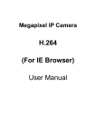
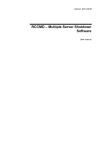
User Manual IN-2901 - Page 1 INSTAR IN-2901 Weatherproof IP-Camera with Night Vision and Motion Detection User Manual Version 1.01 User Manual IN-2901 - Page 2 Information about trademark, copyright and liability This user manual is copyright protected and owned by INSTAR Deutschland. Without a written permit it is not allowed to copy parts or the complete user manual for any kind of reason. All company names, trademarks, product descriptions and Logos which are used in this user manual are owned by the company. INSTAR Deutschland does assume no liability for the validity and actuality of this manual. INSTAR Deutschland does assume no liability for damages which occur by misusing the product in any kind of way. CE-Note This device suites the basic requirements of the European regulations for electromagnetic compliance (2004/108/EC) and the low voltage regulations (2006/95/EC). User Manual IN-2901 - Page 3 Table of Contents 1. Introduction........................................................................................................................................... 5 1.1. Functions........................................................................................................................................ 5 1.2. Delivery Contents.......................................................................................................................... 6 1.3. Accessories (soon available in the OnlineStore)........................................................................ 6 1.4. System Requirements................................................................................................................... 7 1.5. Safety Warnings............................................................................................................................. 7 1.6. Control Elements and Connections............................................................................................. 8 2. Installation............................................................................................................................................. 9 2.1. Preparation..................................................................................................................................... 9 2.2. First Setup...................................................................................................................................... 9 2.2.1. First Setup with “IP Camera Tool”......................................................................................... 9 2.2.2. Extended settings of the “IP Camera Tool”........................................................................ 13 2.2.3. First Setup without “IP Camera Tool”.................................................................................. 14 3. The graphical User interface............................................................................................................. 15 3.1. Menu “Live Video”....................................................................................................................... 18 3.2. Menu “Multi Device”.................................................................................................................... 19 3.2.1. Submenu “Multi-Cameras” (only IE).................................................................................... 19 3.2.2. Submenu “Upgrade Device Firmware”............................................................................... 20 3.2.3. Submenu “Restore Factory Settings”................................................................................. 20 3.2.4. Submenu “Reboot Device”................................................................................................... 20 3.3. Menu “Network”........................................................................................................................... 21 3.3.1. Submenu “IP-Configuration”................................................................................................21 3.3.2. Submenu “ADSL”.................................................................................................................. 22 3.3.3. Submenu “UPnP”.................................................................................................................. 22 3.3.4. Submenu “DDNS Service Settings”.................................................................................... 23 3.4. Menu “Video”............................................................................................................................... 24 3.5. Menu “System”............................................................................................................................ 25 3.5.1. Submenu “Device Info”........................................................................................................ 25 3.5.2. Submenu “Alias Settings”.................................................................................................... 26 3.5.3. Submenu “Date&Time”......................................................................................................... 26 3.5.4. Submenu “User Settings”.................................................................................................... 27 3.5.5. Submenu “Backup & Restore”............................................................................................. 27 3.5.6. Submenu “Log”..................................................................................................................... 28 3.6. Menu “Others”.............................................................................................................................. 29 3.6.1. Submenu “Mail Service”....................................................................................................... 29 3.6.2. Submenu “Ftp Service Settings”......................................................................................... 30 3.6.3. Submenu “Alarm”................................................................................................................. 31 3.6.4. Submenu “Record Path” (only IE)....................................................................................... 32 4. Annex................................................................................................................................................... 33 4.1. Frequently asked Questions....................................................................................................... 33 User Manual IN-2901 - Page 4 4.1.1. How can I connect to my camera over the Internet?......................................................... 33 4.1.2. I have forgot my username or password. What can I do?................................................. 33 4.1.3. I don’t see any picture in the Internet Explorer. Why?....................................................... 34 4.1.4. The color of the picture is a bit gray. What is the reason?................................................ 34 4.2. Specifications............................................................................................................................... 34 5. Warranty and technical Support....................................................................................................... 35 6. Disposal of old electrical appliances............................................................................................... 36 User Manual IN-2901 - Page 5 1. Introduction Congratulations on purchasing our products. You have bought a high quality Security Camera with wireless and wired network connectivity and a integrated web server which allows you to access your camera in your local network and also over the internet. The basic feature of this camera is the transfer of recorded pictures or of live videos over your network. The high quality pictures can be transferred with up to 30fps (frames per second) over the network/internet with the help of MJPEG-Technology. The network integration is based on the TCP/IP-Standard. The integrated Web server allows you to access your camera with almost any web browser for easy control, configuration and maintenance and also to do firmware-Updates of your camera. This IP-Camera is suitable for surveillance on your property, your house/apartment or your office in indoor environment as well as outdoor. 1.1. Functions Fast and programmable RISC Processor Highly sensitive 1/4-inches CMOS-Sensor 300.000 Pixel Night vision with 24 Infrared-LEDs Video Frame Rate: 30fps (QVGA), 15fps (VGA) Resolution: 640x480 (VGA), 320x240 (QVGA) Light Frequent: 50Hz, 60Hz or Outdoor Multistage User management with password protection integrated web server with graphical user interface (GUI) for access via web browser Audio-IN to connect a microphone Protocols: TCP/IP and UDP (network integration), DHCP (automatic network configuration), HTTP (web server), DDNS (dynamic Domain-Name-SystemEntry), SMTP (E-Mail-forwarding, SNTP (Time synchronization) FTP (File transfer) UPnP-capable Direct Internet Connectivity through ADSL Dial up Alarm through motion detect with automatic email notification including 6 pictures per email Snapshots Firmware-Update possible User Manual IN-2901 - Page 6 1.2. Delivery Contents IP-Camera Power supply Software-CD Network cable Quick Installation Guide Camera stand with ball joints Dowel-/Screw set Allen key 1 1 1 1 1 1 1 1 Please check the content of your package carefully for completeness or damages and contact your dealer if any complaints occur. 1.3. Accessories (soon available in the OnlineStore) The following accessories will soon be available for your camera and can be purchased optionally at INSTAR Deutschland: 4,3mm-lens with and without IR-Filter This 4.3mm lenses let you extend the viewing angle to 88°. - The lens with Infrared Cut-filter allows you to see all natural colors. This lets you use the camera as a web- or weather-cam, with no night vision function. (Please note that you will not be able to use the night vision anymore). - The lens without Infrared-Filter however can be used also for night vision. 12mm-telephoto lens without IR-Filter This lens allows you to monitor objects which are more far away from the camera (sample pictures online). This lens also supports night vision. Heater Upgrade Pack The heater comes with a automatic heat regulation. The heater automatically activates itself if the temperature drops below 0 degrees and deactivates itself if the temperature raises +10 degrees. More accessories as well as spare parts you can find on the INSTAR-Website at http://www.instar.de/ User Manual IN-2901 - Page 7 1.4. System Requirements CPU: 2.06GHz or higher Memory Size: 256MB or higher Network Connection: 10Mbit or better Display Card: 64MB or higher Recommended OS: MS Window 2000/XP/Vista/7, Mac OS X, Linux 1.5. Safety Warnings Before using the camera please make sure you have read and understood the following instructions. Only use the power supply that came with your camera. A power supply of another manufacturer might damage the camera. Never touch the lens of the camera. The best focus of the lens has already been set in the factory. If you are turning the lens it will cause a change of the focus so that the video and pictures will be shown unclear. This camera is made to be used outside. The connectors of the connection cable have to be protected from any kind of weather. Only the camera itself is weatherproof. Please follow the state regulations if you are applying it for video surveillance. User Manual IN-2901 - Page 8 1.6. Control Elements and Connections 1 2 3 4 5 6 7 8 Nr. Description Function/Notes 1 Infrared-LEDs Will be automatically activated if surrounding light is too dark 2 Photo element Automatic brightness adjustment 3 Lens Fixed focus 4 Power connection 5V DC Voltage, Connector for the provided power supply 5 Audio Input Connection of a additional microphone 6 Reset-Button Reset of the cameras settings 7 Network connection (LAN) Connection with Switch/Router via Patch-cable 8 Camera stand With ball joint, Fixation with provided allen key User Manual IN-2901 - Page 9 2. Installation Please follow the steps below very carefully to assure a stable operation of your camera. 2.1. Preparation 1. Attach the camera stand on the wall with the dowels and screws provided with the camera. Connect the camera to the stand and secure it with the allen key provided with your camera. You can also do this step after the first installation below. 2. Connect the network interface (LAN) of your camera with a empty plug on your router or switch. Please use the Patch cable provided with your camera. 3. Connect the power supply with the camera and plug the power supply into the wall outlet. Note: If you want to connect your camera directly to your computer you need to have a crossover network cable which is “not” provided with your purchase. You need to buy this cable separately. 2.2. First Setup You can easily set up your IP camera with the provided Software “IP Camera Tool” (little network knowledge necessary) or manually (more network knowledge necessary). 2.2.1. First Setup with “IP Camera Tool” First you have to install this software. Therefore please open the CD-drive and insert the CD that comes with you camera. Now please start the CD and install the “IP Camera Tool” according to your operating system. User Manual IN-2901 - Page 10 A start window welcomes you to the installation: It is highly recommended to close all running programs before installation. Continue by pressing the button “Next >” . Continue with “Next >”. The program starts installing all necessary files. User Manual IN-2901 - Page 11 After installation you will be asked to restart your computer. Please keep the settings on “Yes, I want to restart...” and click “Close”. After your computer has restarted you will find the symbol below on your desktop: “IP Camera Tool”. Start the “IP Camera Tool” with a double click on the symbol. In the following screen your camera should be recognizes in the network. (if you set up the connection of your camera correctly). If you have more than one camera connected then all cameras will be listed in the IP Camera Tool. User Manual IN-2901 - Page 12 Now please mark your new camera with one left click and then please click with the right mouse button on the IP address. The following screen should show. By clicking “Network Configuration” you can now set up the IP address of your camera manually. Only recommended if you know what you are doing. Settings Description Obtain IP from DHCP server If activated the camera receives a automatic IP address from the DHCP Server (Router). IP address The IP has to be in the IP range of your network. Subnet Mask The Subnet Mask of your network (mostly 255.255.255.0). Gateway IP-address of your Internet Gateway/Router DNS Server IP-address of your DNS-Servers (normally the Routers IP) Http Port Port of the cameras Web server (Standard: 80) User Username of the Camera-Administrator (Standard: admin) Password Password of the Camera-Administrators (Standard without) User Manual IN-2901 - Page 13 With this settings the basic set-up of your camera is done. With a double click on the camera / cameras IP address the cameras web server should be automatically opened in your default web browser. After entering the username (admin) without password the graphical interface (GUI) of the camera should be opened. 2.2.2. Extended settings of the “IP Camera Tool” This settings you will not be needed for the first set-up of your camera but it should be described here. In the context menu, which you can open with the right mouse button you can find 4 different options besides “Network Configuration” (see screenshot above). Option Description Basic Properties Display of Device-ID, System-Firmware-Version, Web-GUI-Version Upgrade Firmware Small interface to upgrade the cameras Firmware. We recommend to contact the manufacturer before trying to apply any firmware-Update. Refresh Camera List Manually refreshing of the IP camera listing Flush Arp Buffer If it is not possible to open the Web interface of the camera even it was found in the network you can easily press this option and the ARP-Cache wil be emptied to solve the problem. About IP Camera Tool Information about the Program “IP Camera Tool” User Manual IN-2901 - Page 14 2.2.3. First Setup without “IP Camera Tool” If you already have set your camera before with the “IP Camera Tool” you can ignore this settings. The exactly steps can vary according to your operating system so we will just describe the steps in general. Requirements is a DHCP-Server in your network (mostly a router), because the camera comes with the preset setting “IP-address automatically by DHCP”. 1. Connect the camera as already described in 2.1. Installation on page 9 . 2. Find out the IP address of the camera. You can use a simple IP scanner for this. You may download a small IP scanner on our website: http://www.instar.de/ 3. Open the graphical interface of your camera by entering the IP address in your web browser. (Username: admin, without Password), to start the configuration of your IP camera. User Manual IN-2901 - Page 15 3. The graphical User interface The integrate web server provides you with a graphical interface (GUI) for an easy operation and configuration of your IP camera. Requirement to enter the user interface is the correct set up of your cameras connection as described in step 2. Installation starting from page 9. You can either open the graphical interface with the “IP Camera Tool”, by double clicking the IP address or directly with your Internet-Browser (for example: Internet Explorer, Firefox, Safari) by typing in the cameras IP address (for example 192.168.178.36). First you will be asked to type the username and password. If you have not set up any users, please log in with the standard username “admin” and without any password. After signing in the following screen will show: You can keep the language as “English”. User Manual IN-2901 - Page 16 If you select a different language (in our example “Deutsch”) it will then show the language you have chosen: If you now click on “Sign in”, the graphical web interface of the camera will appear. The web interface can vary according to which web browser you are using. Some control Elements of your camera can be shown with limited access or limited authority/rights according to the user settings (Administrator, Operator or Guest, see the article “System, Submenu “User Settings” in your user manual). The following overview gives you a short introduction of the different operating features and the therefore necessary user rights. User Manual IN-2901 - Page 17 Control element Description User rights Display of the Live-Video activation (only IE) All Groups Display of the Live-Videos deactivate (only IE) All Groups Make a Snapshot (jpg) All Groups Video recording start/stop (only IE) All Groups Displays the Live-Video All Groups Multi-Camera-View configuration (only IE), Firmware-Update, Reset, Restart LAN-, ADSL-, UPnP-, DDND- Settings Administrator OSD-, 180 degree turn of picture, mirroring, time stamp Operator/Administrator Info, Camera name, Time settings, User-Management, Administrator Display-, Log-Settings, Backup/Restore E-Mail-, FTP-, Alarm-Settings, Administrator Record Path for Video recording (nur IE) Multi-Device-View (4 or 9) activation (only IE) Operator/Administrator Frame rate settings (only IE) Operator/Administrator Resolution settings Operator/Administrator Light frequency (50Hz, 60Hz, Outdoor) settings Operator/Administrator Brightness settings Operator/Administrator Contrast settings Operator/Administrator Set to Default-Settings Operator/Administrator Status display of the camera(s) (only IE) All Groups User Manual IN-2901 - Page 18 3.1. Menu “Live Video” After you sign in to your camera you will automatically be redirected to the “Live Video” Menu. In this Menu you will be able to see the Live-Video of your camera. The control elements for controlling the camera are activated in this mode. The Frame rate can only be set by using the Internet Explorer since it needs a ActiveX Plugin which is only supported by IE. The resolution of the camera can be set in 3 steps: 160x120, 320x240 (QVGA) and 640x480 (VGA). The option “Mode” allows you to change the light frequency. If the light frequency is set wrong you might see a white picture or stripes in the Live-Video picture. Therefore the right Frequent needs to be chosen: (Germany: 50Hz, North America: 60Hz). If the area is only lighted by natural light (Sun light) then please set the Mode on “Outdoor” so the light sensor can adjust the brightness automatically. The brightness of the Video can be adjusted from 0 (very dark) to 15 (very bright) and the contrast from 0 (no contrast) to 6 (high contrast). One click on “Default” will automatically reset the brightness settings to 6 and the contrast to 4. In order for the light sensor to work automatically please leave the settings on “Default”. If not the light sensor can not adjust itself which can cause the picture to become too bright in the morning. The Multi-Camera-View (only IE) allows you to see up to 9 Cameras at the same time. The indicators at the bottom of the Live-Video show you which camera is active (green). If the indicator shows you a orange light, the camera can not be connected. If you see a gray indicator it means that no camera is connected at the moment. To set up the Multi-View feature, please follow the steps in Menu “Multi Device”. If you double click on the Live-Video you will be able to show it in Full screen. All other functions that you are seeing are shortly described on page 17. User Manual IN-2901 - Page 19 3.2. Menu “Multi Device” 3.2.1. Submenu “Multi-Cameras” (only IE) The graphical webinterface of the camera allows you to show up to 9 Cameras at the same time (see “Multi-Device-View“). This function is now only available on the Internet Explorer since it requires a ActiveX Plugin. In this Submenu the different cameras will be set. The first camera is always the camera which you are currently configuring. All cameras which can be found in your network will be shown in the box “Device List in LAN”. You can add a camera if you enter the following settings: Parameter Description Alias Name of the Camera (can also be empty) Host IP-address of the camera you like to add Http Port HTTP-Port of the camera you want to add User Username of the camera you want to add Password Password of the camera you want to add User Manual IN-2901 - Page 20 3.2.2. Submenu “Upgrade Device Firmware” The Camera-Firmware and User Interface can be updated through this submenu. While updating the firmware, you should never disconnect the power from the camera because it will cause serious damage to the camera. In the worst case you will not be able anymore to use the camera. The update of the firmware should only be done after contacting your distributor/dealer. 3.2.3. Submenu “Restore Factory Settings” Here you can reset the configuration to factory default settings. You will get a confirmation box where you have to approve the restore. Please note that after restoring the cameras settings all settings will be deleted and you have to set it up same as in the first set-up (see “2.2. First Setup“, Page 9). 3.2.4. Submenu “Reboot Device” Here you can restart your camera. This is normally not necessary. Also for this feature you have to approve first before the reboot. User Manual IN-2901 - Page 21 3.3. Menu “Network” In this menu you can do all settings which are necessary to enter the graphic webinterface (GUI) over the network and via internet. 3.3.1. Submenu “IP-Configuration” The option “Obtain IP from DHCP Server” will cause your camera to receive its IP address, Subnet mask, Gateway and DNS Server information from a DHCP Server in your network. This is mostly done by the router in your network. We recommend you to not use this function since the camera might get a different IP address over the time so that it will not be possible anymore to enter it via Internet without also changing the routers configuration. Therefor it is better to set the IP address manually. The HTTP-Port is automatically set to 80. You can leave this settings. If you have more then one camera you might change these settings. User Manual IN-2901 - Page 22 3.3.2. Submenu “ADSL” Your camera can be connected directly to a DSL Modem in order to dial in the internet. Therefor you have to fill in the username and password of your internet connection. After this the camera needs to be connected with the DSL-Modem. Now please restart the camera in order to make sure it connects to the Internet. 3.3.3. Submenu “UPnP” If your router supports this function you can activate it in your camera. This will allow your router to automatically set the Port forwarding in order to access the camera over the Internet. In the Menu “System” you can check the UpnP status of your camera. Note: If your router does not support UPnP, you have to set up the port forwarding in your router manually in order to access the camera over the Internet. User Manual IN-2901 - Page 23 3.3.4. Submenu “DDNS Service Settings” The easiest way to access your camera over the Internet is DDNS. Details about this you will find at 4.1.1. How can I connect to my camera over the Internet? on page 33. You camera is automatically set in the factory automatically sent the newest IP address to a DDNS Server provided by the manufacturer. You can also choose a different DDNS Service if you are familiar with the settings. Parameter Description Manufacturer-Domain This is the preset DDNS Service Domain (Internet address) of your camera DDNS Service Selection of DDNS Service providers. If selected “None” the preset DDNS Service will automatically be activated. DDNS Username Username of your DDNS-Account DDNS Password Password of your DDNS-Account DDNS Host DDNS-Domain name for your camera DDNS or Proxy Server This settings are only necessary if you use a Proxy Server DDNS oder Proxy Port This settings are only necessary if you use a Proxy Server new Update, ignore all errors This setting is normally not needed User Manual IN-2901 - Page 24 3.4. Menu “Video” In this menu you can do the following setting: Parameter Description OSD (only IE) (On-Screen-Display) Shows the Date and Time in the right corner. You can choose among the colors black, yellow, red, white and blue. Reversal Vertical mirroring of the picture Mirror Horizontal mirroring of the picture Time stamp (only IE) The time stamp can be added to the picture when using IE User Manual IN-2901 - Page 25 3.5. Menu “System” 3.5.1. Submenu “Device Info” This option shows you status information about your camera. You can not do any settings here. Parameter Description Camera ID Every camera has its own Device ID (Mac address) Firmware Version Version of the Cameras-Firmware Web UI Version Version of the graphical User interface Alias Name of the camera (see Submenu “Alias Settings”) Alarm Status Status information weather alarm is activated DDNS Status If the camera is successfully connected to the DDNS Service provider, it will be shown here UPnP Status If activated (see Submenu “UPnP”) the status will be shown here User Manual IN-2901 - Page 26 3.5.2. Submenu “Alias Settings” Particularly if you are using more than one camera it is highly recommended to give each camera a unique name so that you can separate them. 3.5.3. Submenu “Date&Time” Your camera can automatically receive the date and time from your PC andServers. If you have an Internet connection with your camera, it is recommended to use the setting “Sync with NTP Server” and select a preconfigured NTP-Server from the list or if you use a special time server you can also type it by selecting “...”. This will open a field where you can type in the specific server address. Without Internet connection you can just select “Sync with PC Time” to synchronize the time with your computer. Don’t forget to set “Camera Clock Timezone” to the right time zone you are currently in. User Manual IN-2901 - Page 27 3.5.4. Submenu “User Settings” Here you can set up to 8 users including passwords and assign them to different usergroups such as “Administrator”, “Operator” or “Guest”. The group “Administrator” has full user rights and is allowed to change all settings in the camera interface. The group “Operator” can watch the Live-Video, mirror the picture, change the frame rate, resolution, light frequency, brightness, contrast and control the camera. The group “Guest” can only watch the Live-Video. 3.5.5. Submenu “Backup & Restore” Here you can save the settings of your camera (Backup) and restore them. If you do a backup the settings will be saved in a file called “params.bin”. Note: Please note that all data which will be saved in the file is not encrypted and it might be accessed by someone else. This can cause someone to read the passwords. Therefore, please make sure the file is saved in a secure drive. User Manual IN-2901 - Page 28 3.5.6. Submenu “Log” In this menu you can see the access log from your camera. User Manual IN-2901 - Page 29 3.6. Menu “Others” 3.6.1. Submenu “Mail Service” The Email configuration is necessary if you want the camera to automatically send you an Email if an alarm occurs via motion detection. The camera will include 6 pictures in the Email. Whether or not and when the pictures will be sent depends on the settings which are done n the Submenu “Alarm”. The necessary data which you need to fill in all the information can be received from your Email provider or your administrator. After filling in all information please first click on “submit” and after that click on “Test”, to test the settings. With the option “Report Internet IP by Mail” you can automatically have the camera send you the newest (Internet-)IPaddress. If your router is set up accordingly it should be possible to enter the camera from outside your network by typing this Internet IP address in the web browser. User Manual IN-2901 - Page 30 3.6.2. Submenu “Ftp Service Settings” Your camera can send pictures to your FTP Server with the FTP-Protocol included in the camera. You have to fill in all information about your FTP Server. Please ask your Administrator or Provider for the necessary information. Weather or not and when the camera will sent pictures to your FTP Server depends on the settings in Submenu “Alarm”. User Manual IN-2901 - Page 31 3.6.3. Submenu “Alarm” Your camera can react to alarm by motion detection and send pictures via Email (see Submenu “Mail Service”) and/or FTP-Protocol (see Submenu “Ftp Service Settings”). Parameter Description Motion Detect Armed Activated motion detection in the camera Motion Detect Sensibility The higher the setting the more sensitive (range 1-10) Alarm Input Armed Not supported by the camera Trigger Level Not supported by the camera IO Linkage on Alarm Not supported by the camera Output Level Not supported by the camera User Manual IN-2901 - Page 32 Parameter Description Send Mail on Alarm If Alarm/Motion Detect is activated a Email will be sent with 6 pictures in the attachment of the object which caused the motion detection to trigger. Configuration of the Email settings please see 3.6.1. Submenu “Mail Service” on page 29 Upload Image on Alarm If Alarm/Motion Detect is activated pictures will be uploaded in a set time interval which can be set in seconds in the field “Upload Interval (Seconds)”. Information about the configuration of the FTP-Server please see 3.6.2. Submenu “Ftp Service Settings” on page 30 Upload Interval (Seconds)... Please see the settings above Scheduler If you want to set the camera so it records only during a set time you can select the “Scheduler”. Simply select the time and weekdays where the camera should be activated to record. 3.6.4. Submenu “Record Path” (only IE) The “Record Path” will be used for the manual recording in the web interface. If you are viewing the Live-Video in the Internet Explorer and also have set the Motion Detection Alarm the automatic record function will be activated and save video files in case of an alarm. This video will then be saved in the folder which is set at “Alarm Record Path”. Note: If you are using Windows Vista or Windows 7 please add the IP address of the camera to the trusted Sites in order to use the Video recording function. The IP address needs to be added as “Http” and not Https. User Manual IN-2901 - Page 33 4. Annex 4.1. Frequently asked Questions 4.1.1. How can I connect to my camera over the Internet? If you want to access your camera over the Internet it is necessary to fill in the correct settings in the camera and also in your router. In your router you have to set the port forwarding so that the internal (TCP-)Port gets forwarded to the internal IP address (see 3.3.1. Submenu “IP-Configuration”) of your camera. If you have enabled UPnP, this settings should be done automatically by your router. The easiest way to access the camera is using DDNS (DynDNS), because you don’t have to find out any IP address with this service. Since your camera already comes with a preset Manufacturer-DDNS-Service, you only need to remember this name in order to access the camera. If the connection to the Domain Service was successful you can see the Internet address in the following Menu “System”, Submenu “Device Info”. If you would like to use DDNS you have to manually find out the IP address given by your Internet Provider. The easiest way to do so is by having the camera sent this IP by Email (see 3.6.1. Submenu “Mail Service”). You can also find out your external IP address by using website services such as http://www.whatismyip.com. If you have selected a different Port than 80 in your camera you have to use additional information when accessing the camera over the Internet. For example http://c0815.aipcam.com:81 or http://93.214.134.38:81. 4.1.2. I have forgot my username or password. What can I do? In this case please press the reset button on your camera and keep it hold for about 15 seconds. This will delete all settings in the camera. The Administrator account is now set back to username “admin” without any password. Please keep in mind that by doing so you have to set everything in the camera again. User Manual IN-2901 - Page 34 4.1.3. I don’t see any picture in the Internet Explorer. Why? You have to adjust the security settings in the Internet Explorer. The Security settings for ActiveX “Download unsigned ActiveX controls” “Initialize and script ActiveX controls not marked as safe for scripting” and “run ActiveX controls and plug-ins” have to be activated. If the safety is too risky for you and you can accept to have a little less functions you can also use Firefox or Google Chrome to view the camera without any ActiveX. 4.1.4. The color of the picture is a bit gray. What is the reason? The camera allows you to see even at night with 24 Infrared LEDs which are build in. In order to do so the Lens of the camera does not have any Infrared Filter. This effects the picture during the day a little bit. As a result you might see the green color more gray. This is not a defective of the camera. Optionally there is also a lens with Infrared Filter available for your camera. Details you can find here 1.3. Accessories (soon available in the OnlineStore). 4.2. Specifications Attribute Specification Video-Compression MJPEG Video-Compression Video-Resolution 640*480(VGA), 320*240(QVGA) Video-Settings Brightness, Contrast Video-Frame-Rate 30 pictures/s (QVGA), 15 pictures/s (VGA) Network-Connection 10/100 Mbit/s Ethernet WLAN (Wifi) IEEE802.11b/g Night view 24 Infrared-LEDs Operating Voltage 5V DC Voltage maximum power consumption < 6W Surrounding Temperature -5℃ to +55℃ (up to -25℃ with heater) Storage Temperature -20℃ to +70℃ relative humidity 10 bis 85% User Manual IN-2901 - Page 35 5. Warranty and technical Support INSTAR offers a 2-year warranty on its products. During this time you can send your camera for a free repair. This excludes cameras which have been installed custom made Firmware and WebUIs which have not been approved by INSTAR. The warranty is only for hardware parts of the camera. If you are contacting our Service Team please keep your Serial number ready (you can find it on the bottom of your camera). The Serial number starts with “Inxxxxx”. If you are sending your camera for repair please make sure you include the filled out RMA form and attach a copy of the bill. INSTAR Deutschland answers your questions and supports you during the installation of your camera. You can call the German, UK or US Hotline (normal landline phone number) Germany (Frankfurt): +49 69 5960 6997 UK (London): +44 20 8133 2394 US (Palo Alto, Silicon Valley): +1 650 924 9289 Your questions will also be answered by Email [email protected] In addition you can also send your request via normal mail to: INSTAR Deutschland GmbH Auf der Hostert 17 65510 Hünstetten-Bechtheim Germany User Manual IN-2901 - Page 36 6. Disposal of old electrical appliances The European Directive 2002/96/EC on Waste Electrical and Electronic Equipment (WEEE), requires that old household electrical appliances must not be disposed of in the normal unsorted municipal waste stream. Old appliances must be collected separately in order to optimize the recovery and recycling of the materials they contain and reduce the impact on human health and the environment. The crossed out “wheeled bin” symbols on the product reminds you of your obligation, that when you dispose of the appliance it must be separately collected. Consumers should contact their local authority or retailer for information concerning the correct disposal of their old appliance. The package material can be used again. Please make sure you dispose the package material accordingly.