1
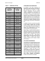
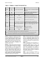
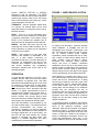
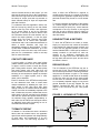
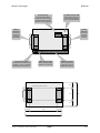
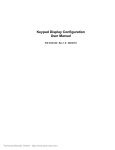
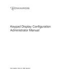
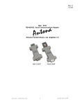
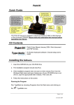
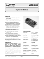
Weeder Technologies WTDIO-M eeder WTDIO-M Technologies 90-A Beal Pkwy NW, Fort Walton Beach, FL 32548 www.weedtech.com Voice/Fax 850-863-5723 Digital I/O Module FEATURES 14 I/O channels; individually configured for input or output. All inputs incorporate a pull-up resistor to 5-volts, simplifying hookup to switch contacts. DIP switch addressable; stack up to 32 modules on the same port for 448 I/O points. Outputs can sink/source up to 25 mA each. Responds to button presses and switch transitions using automatic debounce and typematic repeat with adjustable delay. Decodes 4x4 matrix keypad using autodebounce and typematic repeat. Turns on/off relays, triacs, switching transistors, etc. SPECIFICATIONS One-shot pulse output with software programmable length of 10 to 655,350 µS. Industry standard RS-232 interface. Meets all EIA/TIA-232E and V.28 specifications. Wide power supply range (8 to 30 VDC). Screw-terminal connectors used on all inputs and outputs. DESCRIPTION Connects to the RS-232 serial port of a PC, laptop, or other host. Enables software programs to interact with the hardware of a mechanical world via 14 distinct digital-logic input/output channels. Uses include industrial automation, process control, alarm/security, home automation, remote data entry/retrieval, keypad access systems, etc. Easy to use command set minimizes user learning curve but preserves a robust, feature rich, functional environment. Ideal for quick set-up and run applications. Copyright 2000-2008 by Weeder Technologies Page 1 Digital Inputs Up to 14, accepting 5V logic signals Buffer Type 7 use Schmitt Trigger, 7 use TTL Digital Outputs Up to 14, generating 5V logic signals Output Current 25 mA max per chn. 90 mA total source 90 mA total sink Processor PIC16F882 Clock 4 MHz Communications 9600 Baud, N, 8, 1 Power Requirements +8 to +30 VDC Current Draw 13 to 26 mA, plus any output drive current Operating Temperature -20°C to +80°C Board Dimensions 3.1" x 2.0" x 0.7" Weight 1.8 oz Rev. K Weeder Technologies WTDIO-M STACKABLE DATA MODULES TABLE 1: ADDRESS SETTING HEADER CHARACTER DIP SWITCH SETTING ASCII (HEX) 1=on, 0=off All modules in this series incorporate two EIA/TIA-232E serial ports which communicate at 9600 baud, no parity, 8 data bits and 1 stop bit. DB9 connectors are jumpered to satisfy hardware handshaking. The port labeled ‘‘HOST’’ is configured as a DCE device and should be connected to a PC’s serial port. The port labeled ‘‘SLAVE’’ is a DTE device and can be left open, or connected to another module’s host port. Up to 32 modules can be chained together in this fashion to form a network. Either plugged together end to end, or separated by a cable. Because a module contains two individual bi-directional ports which pass data through, it also acts as a repeater, extending the total allowable length of the RS-232 communications line. 1 2 3 4 5 A (41) 00000 B (42) 00001 C (43) 00010 D (44) 00011 E (45) 00100 F (46) 00101 G (47) 00110 H (48) 00111 I (49) 01000 J (4A) 01001 K (4B) 01010 L (4C) 01011 M (4D) 01100 N (4E) 01101 O (4F) 01110 P (50) 01111 a (61) 10000 b (62) 10001 c (63) 10010 d (64) 10011 e (65) 10100 f (66) 10101 COLLISION CONTENTION g (67) 10110 h (68) 10111 i (69) 11000 j (6A) 11001 k (6B) 11010 l (6C) 11011 m (6D) 11100 n (6E) 11101 o (6F) 11110 p (70) 11111 The utilization of the communications line can be thought of more as a single, bi-directional, data bus, operated in a multi-drop mode rather then a standard RS-232 data link. A transmission from a data module travels in both directions, upstream to the host, and downstream to signal other modules that it has seized the line. Before transmitting, a module will listen to the communications line and wait for quiescence. After a silent period equal to the length of one byte, the waiting module will send its data packet using a Carrier Sense Multiple Access with Collision Detection communications protocol. See the application note (AN100) at the back of this manual for more details. Copyright 2000-2008 by Weeder Technologies A modem can serve as the host for remote operation, but since a modem uses a DCE port, a ‘‘null modem’’ adapter must be placed between the modem and the data module’s host port. A gender changer may also be required. In addition, any hardware/software flow control must be disabled in the terminal program. Each module in a network should be set to a different address using the on-board 32-position DIP switch. A module will only respond to data packets that begin with its’ own unique header character, which is determined by this DIP switch setting. See Table 1. Data packets transmitted by a module will also begin with this header character. The host PC can use the header character to address each individual module in a network, and to identify a module which is talking. Page 2 Rev. K Weeder Technologies WTDIO-M COMMAND SET instructed to remain at this new state, or simulate a one-shot multivibrator and return to the original state after a user defined time-out period in the range of 10 to 655,350 µS. Note, the value assigned to the time variable is multiplied by 10 when loaded. The host PC communicates with the Digital I/O Module using a command set comprised of standard ASCII character strings as depicted in Table 2. Each I/O channel will be configured as either an input or output depending on the need of the particular function evoked by the reception of a command string. A detailed description of each command and configuration follows. BUTTON - Configures the specified I/O channel to sense and respond to a low-going transition such as the press of a normally-open button wired to ground. A built-in debounce feature is used to mask multiple transitions produced by contact bounce. The response character string will be retransmitted at a rate determined by TYPEMATIC while the button is held down. HIGH/LOW - Changes the specified I/O channel to an output, if not already, and sets it to the desired logic state. The I/O channel can be TABLE 2: COMMAND SET TITLE COMMAND DESCRIPTION HIGH H chn time Make channel chn an output and set high for time x10 microseconds. chn = A-N, time = 1 to 65535. If time omitted, chn remains high.(Note 3) LOW L chn time Make channel chn an output and set it low for time x10 microseconds. chn = A-N, time = 1 to 65535. If time omitted, chn remains low. (Note 3) BUTTON B chn Make channel chn an input and respond to button press. Returns "chn L" when pressed. Repeated if held down. chn = A-N. (Note 3) SWITCH S chn Make channel chn an input and respond to switch transition. Returns "chn L" or "chn H" when toggled. chn = A-N. (Note 3) MATRIX M Use channels G-J as outputs and channels K-N as inputs to decode a 4x4 matrix keypad. Returns "M row col ". row = G-J, col = K-N. (Note 3) READ R chn If chn = A-N, read state. Returns "chn H" or "chn L". If chn = P, read channels A-H as an 8-bit parallel port (A = LSB). Returns 00 to FF. If chn omitted, read all channels as parallel port. Returns 0000 to 3FFF. WRITE W data Make required number of channels an output (see text), and writes data to them as a parallel port. data = 0 to 3FFF. (A = LSB) (Note 3) INPUT I chn If chn = A-N, make channel chn an input. If chn = P, make 8-bit port channels (A-H) an input. If chn omitted, make all an input. (Note 3) TYPEMATIC T chn time Sets the typematic repeat delay for a specific input channel which will be used for BUTTON or MATRIX functions. chn = A-N, time = 1 to 15 listed in 1/10 of a second. Default = 3 (0.3 sec). If time = 0, typematic repeat disabled. If time omitted, reads the current setting. (Note 3) ECHO X value Turns on or off the reception confirmation echo. Value = 0 or 1. 0 = off, 1 = on, default = 1. If value omitted, reads the current setting. ERROR ? This character will be returned after an invalid command or variable. RESET ! This character will be returned after a power-on reset, or brownout. Note 1: All command strings sent to the data module should be preceded with the header character (see Table 1), and terminated with a carriage return. All responses from the data module will also appear in this format. Note 2: Any spaces shown above in the listing of the command strings are for clarity only. They should not be included in the actual transmission from the host, nor expected in a response from the data module. Note 3: If ECHO is on, after successful execution this command will be echoed back to the host in the same format as received. Copyright 2000-2008 by Weeder Technologies Page 3 Rev. K Weeder Technologies WTDIO-M TABLE 3: TERMINAL / CONNECTOR DESCRIPTION NAME TYPE ELECTRICAL SPECS COMMENTS: HOST DB9 EIA/TIA-232E Standard RS-232 serial port configured as DCE. Connects to host PC. Hardware handshake jumpered. EIA/TIA-232E Standard RS-232 serial port configured as DTE. Can be connected to another data module's HOST port for networking. SLAVE (female) DB9 (male) Power Source Jumper N/A Power source selection jumper. Selects either external, or port powered. (Note 1) + Screw Term +8 to +30 VDC External unregulated power supply input. - Screw Term GND External power supply ground. A–N Input If configured as input, will decode logic VIL = 0 to 0.8V TTL, 0 to 1.0V ST levels. All channels incorporate a pull-up Screw Term VIH = 2.0 to 5V TTL, 4.0 to 5V ST resistor to 5 volts which will hold it high if left Max = -0.3 to 5.3V (Note 2) open. A-G = Schmitt Trigger, H-N = TTL. A–N Output Screw Term +5 Screw Term +5V @ < 100 mA GND Screw Term GND VOL = 0 to 0.6V VOH = 4.3 to 5V If configured as output, will change logic Sink/Source 25mA (Note 3) state upon command. Regulated 5 volt output. Logic ground. Note 1: Selecting "port powered" will draw from the power supply source of an upstream data module. Caution, the COM port of a PC or laptop does not supply enough current to serve as the power supply source. Note 2: Due to internal 20 mA clamping diodes, a series input resistor will increase the maximum allowable input voltage. Note 3: Each I/O channel can individually sink or source 25 mA. Maximum current sunk by all output channels combined should not exceed 90 mA. Maximum current sourced by all output channels combined should not exceed 90 mA. SWITCH - Configures the specified I/O channel to sense and respond to a logic transition. This can be an SPST toggle switch wired to ground. A built-in debounce feature is used to mask multiple transitions produced by contact bounce. This configuration differs from BUTTON in that it reports both low to high, and high to low transitions, and does not incorporate the typematic repeat function. READ - Reads the logic state of a specified I/O channel, or reads multiple channels as a parallel port in hexadecimal notation. Note, this command will not change the direction (input or output) of a channel, therefore it can be used to check the current state of an output as well as read an input. WRITE - Writes data to the I/O channels as a 4, 8, 12 or 14-bit parallel port. The data must be in hexadecimal notation from 0 to 3FFF. The number of characters (nibbles) in the data field determines how many channels are changed to output and manipulated. For example, if data = F, channels A-D will be set high, all other channels will not be effected. In contrast, if data = 000F, channels A-D will be set high and channels E-N will be set low. MATRIX - Configures the last eight I/O channels to be used to automatically scan and decode a 4x4 matrix keypad. To hookup to a keypad, connect channels G-J to the keypad’s "row" contacts, and channels K-N to the keypad’s "col" contacts. When a button is pressed, the "row" and "col" channels which make contact are reported to the host. A built-in debounce feature is used to mask multiple transitions produced by contact bounce. The response character string will be retransmitted at the rate determined by TYPEMATIC while a button is held down. Copyright 2000-2008 by Weeder Technologies INPUT - Sets the specified I/O channel, or multiple parallel port channels, to a high impedance state (input), and cancels any other Page 4 Rev. K Weeder Technologies WTDIO-M function (SWITCH, BUTTON or MATRIX) assigned to that I/O channel(s). The READ command can then be used to retrieve data from external logic sources. Note, this is the natural state of all I/O channels upon power-up, or after a power disruption or brown out. FIGURE 1: MODCOM APPLICATION TYPEMATIC - Sets the typematic repeat delay of a specific I/O channel which will be used when that channel is configured for BUTTON or MATRIX functions. ECHO – Turns on or off the confirmation echo which is used to verify reception of a command. If reception confirmation is not needed, turning ECHO off will increase the repetitive rate at which the host can manipulate the I/O channels. ERROR - Any data string sent from the host containing the correct header character but an invalid command or variable will be responded to with this error indicator. An easy-to-use Windows™ software package called "ModCom" is available and can be downloaded from Weeder Technologies' web site. This program will allow the user to quickly set up custom buttons which transmit commands, custom windows that poll for data, and a variety of other screen objects such as slider controls, event counters & timers, bar-graph level indicators, button selection arrays, and more. In addition, conditional statements can be set up to take action when specific events or conditions are met, sequences can be written and then called by other screen objects during run-time, and data can be logged to a file automatically at user-defined intervals. RESET - Upon power-up or any other reset condition, this indicator is transmitted to the host. If a data module encounters an unintentional reset due to a power disruption or brown-out, all configuration info will be lost. Therefore, upon reception of this indicator, the host should retransmit any configuration information originally sent at the start of the operating program. OPERATION Once ModCom is installed and running, go to the <Communicate> menu item at the top of the screen and click on <Send/Receive>. A dialog box will pop up which you can use to type in the commands from Table 2, transmit them directly to the data module, and see the response coming back. Use this dialog box to familiarize yourself with the command set and to experiment with the various features supported by the module. The experience gained here is significant since these are the same command strings you will use when setting up the other objects in ModCom. To hook the data module to a host PC, use a standard RS-232 cable with male and female DB9 connectors on opposite ends. This cable should be wired straight through (pin to pin) with no crossover of the data lines. In other words, not a null modem cable. Connect a suitable DC power source to the + and - terminals of the data module. It is highly recommended to use an ungrounded AC adapter such as that which is available from Weeder Technologies. This will provide isolation and prevent ground loops which are commonly created if the power supply and computer are grounded at different points. To operate the Digital I/O Module, start with the sample application "WTDIO.mod" which can be found in the ModCom subfolder called "Samples". After this file is opened, it will appear as shown in Figure 1. To start the main run-loop, click on the green toolbar button at the top of the screen. At this time, ModCom will transmit a series of initialization commands, found in the <Run-Loop><Initialization> menu item, to the WTDIO module to set up its I/O channels for the When the data module is first powered up, the red LED will flash briefly. This indicates that the on-board microcontroller has booted up, successfully completed its internal diagnostic test, and has transmitted the reset character to the host to signal that it is up and running. The red LED will also flash anytime the module receives or transmits any data packet, thus making it a valuable diagnostic tool when troubleshooting communications problems. Copyright 2000-2008 by Weeder Technologies Page 5 Rev. K Weeder Technologies WTDIO-M various functions shown on the screen. You can then use the mouse to click on the Push Buttons and control the logic state of the channels which are setup for output, and hook up switches to those channels setup for input and experiment with their functions. order to allow the WTDIO-M to respond to multiple switch closures on a single I/O channel even though the typematic repeat delay for that particular channel may be set to a much slower rate. To set the typematic repeat delay of the buttons on a matrix keypad, work with the I/O channels which are setup for input (K-N). These channels correspond to the four columns of the keypad and may be set to different values if wishing to have certain button columns repeat at a different rate then others. To understand how this application works, first halt the run-loop by clicking on the red toolbar button at the top of the screen, then right-click on any screen object to pull up its properties dialog box. In this box you will be able to view the commands which the Push Buttons use to control the output channels, or view the input strings which the Event Counters and Event Timers watch for to control their operation. Channels G and H use conditional statements to detect a switch transition and send the appropriate message to their windows. To view or edit these conditional statements, go to the <Run-Loop> menu item at the top of the screen and click on <Conditionals>. Refer to the help files for more information. USING BUTTONS & SWITCHES To hook the WTDIO-M to a button or switch, simply run a wire from one contact of the switch to the desired I/O channel's screw terminal, and a wire from the opposite contact to the screw terminal labeled GND. A 10KΩ pull-up resistor is already included on the board for each I/O channel so no additional components are required. The logic level at the I/O channel will be high when the switch is open, and low when the switch is closed. CONTACT DEBOUNCE A typical switch or button uses metal plates (called contacts) which can be moved together or apart in order to make or break the current path. During switch closure, when these plates first make contact with each other they will bounce several times before coming to rest. This bouncing of the contacts will appear as multiple transitions to a digital system, and in most cases, not be desirable. DRIVING RELAYS The I/O channels of the WTDIO-M can sink or source only 25 mA. This current is insufficient to drive most relays therefore a switching transistor must be used as shown in Figure 2. The voltage applied to V+ should be that which is necessary to drive the relay and can be the same power source which is connected to the data module, or a completely separate supply as long as the ground terminals of the two supplies are tied together. Caution! DO NOT use the +5 volt output of the WTDIO-M as your relay power source. Each I/O channel of the WTDIO-M incorporates its own debounce timer used to mask these multiple transitions by disabling the input for a short period of time after each logic state change. When an I/O channel detects a change of state, the action is immediately reported to the host, its debounce counter is loaded with a time value equal to 100 mS, and the input is disabled until this time period has lapsed. Because each I/O channel's timer operates independently of each other, the WTDIO-M can still report actions on additional inputs while its waiting for one or more debounce timers to expire. FIGURE 2: HOOKING UP TO RELAYS V+ Relay coil 1N4001 To I/O Channel TYPEMATIC REPEAT 1K In addition to the debounce timers mentioned above, each I/O channel has its own typematic repeat timer which operates both independently of each other, and independent of its own debounce timer. The later being important in Copyright 2000-2008 by Weeder Technologies Page 6 2N2222 or equivalent Rev. K Weeder Technologies WTDIO-M Trans/Rec Indicator LED Flashes whenever there is communications between host PC and Data Module. Address Setting This DIP switch sets the address of the Data Module and determines the header character of its data packets. A B C D E F G H Power Supply Inputs Will accept any voltage between 8 and 30 VDC. Power Source Jumper Draw power from external input terminals, or from an upstream Data Module via the host port. RS-232 Host Port Connects to the serial port of the host PC. HOST SLAVE RS-232 Slave Port Connects to the Host port of another Data Module. I J K L M N +5 GND Digital I/O Channels TTL level inputs and outputs which can be individually configured. 0.5" Holes will accept size 4-40 screws 1.0" 2.0" 0.5" 0.375" 0.375" 2.35" 3.1" Copyright 2000-2008 by Weeder Technologies Page 7 Rev. K Weeder Technologies Copyright 2000-2008 by Weeder Technologies WTDIO-M Page 8 Rev. K