1
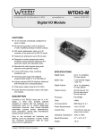
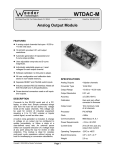
Weeder Technologies DIO-SSR eeder DIO-SSR Technologies 90-A Beal Pkwy NW, Fort Walton Beach, FL 32548 www.weedtech.com 850-863-5723 Relay Controller Module DESCRIPTION The Relay Controller Module as described here serves as the host to the Solid Sate Relay Module (part number WTSSR-M). The Controller can work in conjunction with, or take the place of a PC. It communicates with the Relay Module using its command set in the same way as a PC and allows manual operation of each relay via a remote data link. Switches wired to the inputs of the Controller will be able to set the on/off states of up to 10 relays, two WTSSR-M units. OPERATION Connect a power source in the range of 8 to 30VDC to the screw terminals labeled + and - on the board. Connect one end of an RS232 communications link to the port labeled "SLAVE" on the Controller Module, and the other end to the "HOST" port of a Relay Module. To connect switches to the board, run a wire from one of the contact pairs to an input channel, and a wire from the opposite contact to the GND terminal. COMMAND VERIFICATION Each time the Controller Module sends a command to the Relay Module, it listens for an acknowledgment which will indicate that the command was successfully delivered and the Relay Module performed the desired operation. If this response is not received within 20mS, the controller retransmits the command and waits another 20mS. If still no response, it transmits the command one last time and then returns to normal operation. This all happens within 0.06 seconds from the time that the switch was toggled. Note, the Relay Module must have its ECHO turned on to make use of this feature. Switches wired to input channels A thru E of the Controller Module will control channels A thru E of a Relay Module which has its header character set to address "A". Switches wired to input channels F thru J will control relay channels A thru E of a Relay Module which has its header character set to address "B". CONTACT DEBOUNCE INITIALIZATION During switch closure, when the metal plates of a switch first make contact with each other they will bounce several times before coming to rest. Each of the input channels of the Controller Module incorporates its own debounce timer used to mask these multiple transitions. When a switch closure is detected on an input channel, the debounce timer associated with that channel is loaded with a value equal to 0.1 seconds. The input is then disabled until this time period has lapsed. The other inputs are not effected. When the Controller Module first powers up, it reads the current state of the switches and sends the appropriate commands to the Relay Module to set each relay so that it matches the state of its corresponding switch. For this initialization procedure to function properly, make sure the communications link and the Relay Module are up and running before applying power to the Controller Module. Copyright 2008 by Weeder Technologies Page 1 Rev. B Weeder Technologies DIO-SSR SPECIFICATIONS HOOKING TO SWITCH CONTACTS 1K (Note 1) Digital Inputs 10 inputs, accepting dry switch contacts. Buffer Type 7 use Schmitt Trigger, 3 use TTL Input Clamp Current ±20mA Maximum Processor PIC16F882 Clock 4 MHz Communications 9600 Baud, N, 8, 1 Power Requirements +8 to +30 VDC Current Draw 13 to 26 mA Operating Temperature -20°C to +80°C Board Dimensions 3.1" x 2.0" x 0.7" Weight 1.8 oz Chn A Chn B Chn C Chn D Chn E GND DIO-SSR Note 1: Placing a 1K resistor at the input of each channel will provide added protection against harmful transient voltages produced by static electricity or other electrical discharges. TERMINAL / CONNECTOR DESCRIPTION NAME TYPE ELECTRICAL SPECS COMMENTS: HOST DB9 EIA/TIA-232E Standard RS-232 serial port configured as DCE. Connects to host PC. Hardware handshake jumpered. EIA/TIA-232E Standard RS-232 serial port configured as DTE. Connects to the HOST port of a WTSSR-M. Two WTSSR-M units can be connected. SLAVE (female) DB9 (male) Power Source Jumper N/A + Screw Term +8 to +30 VDC - Screw Term GND A–J Power source selection jumper. Selects either external, or port powered. (Note 1) External unregulated power supply input. External power supply ground. Will decode logic levels present at the VIL = 0 to 0.8V TTL, 0 to 1.0V ST inputs and automatically report any change Screw Term VIH = 2.0 to 5V TTL, 4.0 to 5V ST of state. All channels incorporate a pull-up Max = -0.3 to 5.3V (Note 2) resistor to 5 volts which will hold it high if left open. A-G = Schmitt Trigger, H-J = TTL. +5 Screw Term +5V @ < 100 mA GND Screw Term GND Regulated 5 volt output. Logic ground which can be used for the common side of each switch which is connected to an input channel. Note 1: Selecting "port powered" will draw from the power supply source of an upstream data module. Caution, the COM port of a PC or laptop does not supply enough current to serve as the power supply source. Note 2: Due to internal 20 mA clamping diodes, a series input resistor will increase the maximum allowable input voltage. Copyright 2008 by Weeder Technologies Page 2 Rev. B Weeder Technologies DIO-SSR Trans/Rec Indicator LED Flashes whenever there is communications between this module and WTSSR-M. Address Setting This DIP switch sets the address of the Data Module and determines the header character of its data packets. A B C D E F G H Power Supply Inputs Will accept any voltage between 8 and 30 VDC. Power Source Jumper Draw power from external input terminals, or from an upstream Data Module via the host port. RS-232 Host Port Connects to the serial port of the host PC. HOST SLAVE RS-232 Slave Port Connects to the Host port of WTSSR-M module. I J K L M N +5 GND Switch Input Channels Can be wired directly to dry switch contacts. Built in pull-up resistors to +5V. 0.5" Holes will accept size 4-40 screws 1.0" 2.0" 0.5" 0.375" 0.375" 2.35" 3.1" Copyright 2008 by Weeder Technologies Page 3 Rev. B Weeder Technologies Copyright 2008 by Weeder Technologies DIO-SSR Page 4 Rev. B