1
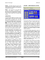
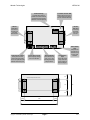
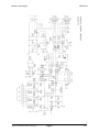
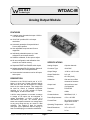
Weeder Technologies WTDAC-M eeder WTDAC-M Technologies 90-A Beal Pkwy NW, Fort Walton Beach, FL 32548 www.weedtech.com Voice/Fax 850-863-5723 Analog Output Module FEATURES 4 analog output channels that span -10.00 to +10.00 volts each. 12-bit DAC provides 0.01-volt output resolutions. Automatic generation of trapezoidal and S-curve slope profiles. User adjustable ramp-rate and S-curve magnitude. Individually selectable power-up / reset voltages for each output channel. Software calibrated; no trim-pots to adjust. All user configuration and calibration data stored in non-volatile memory. SPECIFICATIONS Separate RESET and PAUSE switch inputs. Analog Outputs 4 bipolar channels Industry standard RS-232 interface. Meets all EIA/TIA-232E and V.28 specifications. Converter Type 12-bit DAC Output Range -10.00 to +10.00 volts Output Resolution 0.01 volt Accuracy ±2 LSB (10mV) Calibration Gain and zero offset corrected in firmware Output Load 1KΩ minimum, total of all channels Processor PIC16F628 Clock 4 MHz Communications 9600 Baud, N, 8, 1 Power Requirements +15 to +30 VDC Current Draw 24 to 26 mA, plus any output drive current Operating Temperature -20°C to +80°C Board Dimensions 3.5" x 2.0" x 0.7" Weight 2.0 oz Screw-terminal connectors used on all inputs and outputs. DESCRIPTION Connects to the RS-232 serial port of a PC, laptop, or other host. Simple command strings sent from the host will set distinct DC voltage levels at the output channels. This voltage can be used for control of industrial equipment requiring a 0 to 10 VDC unipolar or bipolar control signal, as well as other uses. A built-in ramp generator is included. A change in voltage on an output can be configured to update immediately, or follow a slope at a user-defined ramp rate. An external pause switch can suspend execution of a voltage slope at any point along the way for review or data collection. This module is ideal for complex multi-point cyclic operations without relying on host for timekeeping or conversion calculations. Copyright 2000-2006 by Weeder Technologies Page 1 Rev. F Weeder Technologies WTDAC-M STACKABLE DATA MODULES TABLE 1: ADDRESS SETTING HEADER CHARACTER DIP SWITCH SETTING ASCII (HEX) 1=on, 0=off All modules in this series incorporate two EIA/TIA-232E serial ports which communicate at 9600 baud, no parity, 8 data bits and 1 stop bit. DB9 connectors are jumpered to satisfy hardware handshaking. The port labeled ‘‘HOST’’ is configured as a DCE device and should be connected to a PC’s serial port. The port labeled ‘‘SLAVE’’ is a DTE device and can be left open, or connected to another module’s host port. Up to 32 modules can be chained together in this fashion to form a network. Either plugged together end to end, or separated by a cable. Because a module contains two individual bi-directional ports which pass data through, it also acts as a repeater, extending the total allowable length of the RS-232 communications line. 1 2 3 4 5 A (41) 00000 B (42) 00001 C (43) 00010 D (44) 00011 E (45) 00100 F (46) 00101 G (47) 00110 H (48) 00111 I (49) 01000 J (4A) 01001 K (4B) 01010 L (4C) 01011 M (4D) 01100 N (4E) 01101 O (4F) 01110 P (50) 01111 a (61) 10000 b (62) 10001 c (63) 10010 d (64) 10011 e (65) 10100 f (66) 10101 COLLISION CONTENTION g (67) 10110 h (68) 10111 i (69) 11000 j (6A) 11001 k (6B) 11010 l (6C) 11011 m (6D) 11100 n (6E) 11101 o (6F) 11110 p (70) 11111 The utilization of the communications line can be thought of more as a single, bi-directional, data bus, operated in a multi-drop mode rather then a standard RS-232 data link. A transmission from a data module travels in both directions, upstream to the host, and downstream to signal other modules that it has seized the line. Before transmitting, a module will listen to the communications line and wait for quiescence. After a silent period equal to the length of one byte, the waiting module will send its data packet using a Carrier Sense Multiple Access with Collision Detection communications protocol. See the application note (AN100) at the back of this manual for more details. Copyright 2000-2006 by Weeder Technologies A modem can serve as the host for remote operation, but since a modem uses a DCE port, a ‘‘null modem’’ adapter must be placed between the modem and the data module’s host port. A gender changer may also be required. In addition, any hardware/software flow control must be disabled in the terminal program. Each module in a network should be set to a different address using the on-board 32-position DIP switch. A module will only respond to data packets that begin with its’ own unique header character, which is determined by this DIP switch setting. See Table 1. Data packets transmitted by a module will also begin with this header character. The host PC can use the header character to address each individual module in a network, and to identify a module which is talking. Page 2 Rev. F Weeder Technologies WTDAC-M VOLTAGE - Sets the voltage on a specific output channel using 0.01-volt resolution. The desired voltage can be in the range of -10.00 volts to +10.00 volts and is listed in 1/100 of a volt (no decimal point). COMMAND SET The host PC communicates with the Analog Output Module using a command set comprised of standard ASCII character strings as depicted in Table 2. A function can be initiated by the host and then left to be independently executed. All voltage representation data is listed in standard decimal notation for ease of use. A detailed description of each command follows. TRAPEZOID - Ramps the voltage on a specific output channel to a desired voltage level using a trapezoidal shaped slope profile. After reception of this command, the voltage on the output will begin increasing or decreasing towards the target voltage at a rate determined by TABLE 2: COMMAND SET TITLE COMMAND DESCRIPTION VOLTAGE V chn value Sets the voltage on an output channel. chn = A-D, value = 0 to ±1000 and is listed in 1/100 of a volt. Example: 825 = 8.25 volts. (Note 3, 4) TRAPEZOID T chn value Ramps the voltage on an output channel to a desired level using a trapezoidal shaped profile. Slope is determined by RAMP-RATE. chn = A-D, value = 0 to ±1000 and is listed in 1/100 of a volt. (Note 5) S-CURVE S chn value Ramps the voltage on an output channel to a desired level using an S-curve shaped profile. Slope is determined by RAMP-RATE. chn = A-D, value = 0 to ±1000 and is listed in 1/100 of a volt. (Note 5) PADDING P chn value Sets the magnitude of the curvature used in the S-CURVE function for a specific channel. chn = A-D, value = 1 to 3. Default = 2. (Note 3, 4) RAMP-RATE R chn value Sets the ramp rate used in the TRAPEZOID and S-CURVE functions for a specific channel. chn = A-D, value = 1 to 255 and is listed in 1/100 of a volt/sec. Example: 125 = 1.25 V/sec. Default = 50. (Note 3, 4) WAIT W value Loads an internal timer which will signal the host when expired. Allows time-derived, steady-state outputs in cyclic routines. value = 1 to 255 and is in 1/10 of a second. Example: 205 = 20.5 seconds. (Note 5) DEFAULT D chn value Sets the default voltage level for a specific output channel which will be loaded upon power-up, brown-out or an external reset. chn = A-D, value = 0 to ±1000 listed in 1/100 of a volt. Default = 0. (Note 3, 4) CALIBRATE C chn v1 v2 Takes the actual measured values of two voltage set-points and computes the calibration coefficients for a given channel. chn = A-D, v1 is the measured voltage after writing 800 to the output channel, v2 is the measured voltage after writing -800 to the output channel. All values are listed in 1/100 of a volt. Example: 825 = 8.25 V. (Note 3, 6) ECHO X value Turns on or off the reception confirmation echo. Value = 0 or 1. 0 = off, 1 = on, default = 1. If value omitted, reads the current setting. ERROR ? This character will be returned after an invalid command or variable. RESET ! This character will be returned after a power-on reset, or brownout. Note 1: All command strings sent to the data module should be preceded with the header character (see Table 1), and terminated with a carriage return. All responses from the data module will also appear in this format. Note 2: Any spaces shown above in the listing of the command strings are for clarity only. They should not be included in the actual transmission from the host, nor expected in a response from the data module. Note 3: If ECHO is on, after successful execution this command will be echoed back to the host in the same format as received. Note 4: If value is omitted, reads the current setting which will be returned to the host in the same format as above. Note 5: After this function has been completed, the command will be echoed back to the host in the same format as received. Note 6: The data module has been calibrated at the factory, it is not necessary to perform this operation prior to use. Copyright 2000-2006 by Weeder Technologies Page 3 Rev. F Weeder Technologies WTDAC-M TABLE 3: TERMINAL / CONNECTOR DESCRIPTION NAME TYPE ELECTRICAL SPECS COMMENTS: HOST DB9 EIA/TIA-232E Standard RS-232 serial port configured as DCE. Connects to host PC. Hardware handshake jumpered. EIA/TIA-232E Standard RS-232 serial port configured as DTE. Can be connected to another data module's HOST port for networking. SLAVE (female) DB9 (male) Power Source Jumper N/A Power source selection jumper. Selects either external, or port powered. (Note 1) + Screw Term +15 to +30 VDC External unregulated power supply input. - Screw Term GND A-D Screw Term Range = -10VDC to +10VDC Minimum load = 1KΩ RESET Screw Term N/A Normally-open external reset switch. PAUSE Screw Term N/A Normally-open pause switch. External power supply ground. Analog output channels. Note 1: Selecting "port powered" will draw from the power supply source of an upstream data module. Caution, the COM port of a PC or laptop does not supply enough current to serve as the power supply source. RAMP-RATE. Note, the communications port will be disabled until this function has completed. This function is useful during a cyclic routine when a steady output voltage is desired for a specific time period without having to rely on timekeeping from the host. Note, the communications port will be disabled until this function has completed. S-CURVE - Ramps the voltage on a specific output channel to a desired voltage level using an S-curve shaped slope profile. After reception of this command, the voltage on the output will begin increasing or decreasing towards the target voltage at a rate determined by RAMP-RATE. Because of the curve added to the beginning and end of this slope, the total ramp time will be slightly longer then an equivalent trapezoidal slope. Note, the communications port will be disabled until this function has completed. DEFAULT - Sets the default voltage level for a specific output channel which will be loaded upon power-up, brown-out, or an external reset. CALIBRATE - Takes the actual measured values of two voltage set-points and computes the calibration coefficients for a specific output channel. To calibrate, set the output channel to 8.00 volts and measure the true voltage with a multimeter. Then set the output to -8.00 volts and measure the true voltage. Include the results in the CALIBRATE command string using the negative sign as the separator. The WTDAC will use this data to calculate the gain and offset coefficients particular to that channel and store it in non-volatile memory. Note, the module has been calibrated at the factory, it is not necessary to perform this operation prior to use. PADDING - Sets the magnitude of the curvature used in the S-CURVE function for a specific output channel. Select form 1 to 3, 1 being the least amount of curvature, 3 being the most. RAMP-RATE - Sets the ramp rate used in the TRAPEZOID and S-CURVE functions for a specific output channel. Selectable range is from 0.01 V/sec to 2.55 V/sec and is listed in 1/100 of a volt/sec (no decimal point). ECHO – Turns on or off the confirmation echo which is used to verify reception of a command. If reception confirmation is not needed, turning ECHO off will increase the repetitive rate at which the host can manipulate the outputs. WAIT - Loads an internal timer which will signal the host when the time interval has expired. Selectable range is from 0.1 sec to 25.5 sec and is listed in 1/10 of a second (no decimal point). Copyright 2000-2006 by Weeder Technologies Page 4 Rev. F Weeder Technologies WTDAC-M ERROR - Any data string sent from the host containing the correct header character but an invalid command or variable will be responded to with this error indicator. FIGURE 1: MODCOM APPLICATION RESET - Upon power-up or any other reset condition, this indicator is transmitted to the host. Note, all user configuration and calibration data is stored in non-volatile memory. Therefore, a reset or loss of power will not corrupt these settings. OPERATION To hook the data module to a host PC, use a standard RS-232 cable with male and female DB9 connectors on opposite ends. This cable should be wired straight through (pin to pin) with no crossover of the data lines. In other words, not a null modem cable. Connect a suitable DC power source to the + and - terminals of the data module. It is highly recommended to use an ungrounded AC adapter such as that which is available from Weeder Technologies. This will provide isolation and prevent ground loops which are commonly created if the power supply and computer are grounded at different points. box will pop up which you can use to type in the commands from Table 2, transmit them directly to the data module, and see the response coming back. Use this dialog box to familiarize yourself with the command set and to experiment with the various features supported by the module. The experience gained here is significant since these are the same command strings you will use when setting up the other objects in ModCom. When the data module is first powered up, the red LED will flash briefly. This indicates that the on-board microcontroller has booted up, successfully completed its internal diagnostic test, and has transmitted the reset character to the host to signal that it is up and running. The red LED will also flash anytime the module receives or transmits any data packet, thus making it a valuable diagnostic tool when troubleshooting communications problems. To control the Analog Output Module, start with the sample application "WTDAC.mod" which can be found in the ModCom subfolder called "Samples". After this file is opened, it will appear as shown in Figure 1. To start the main run-loop, click on the green toolbar button at the top of the screen. At this point, you can move the two Slider Controls to adjust the voltages on channels A and B in real time. The current voltage will be shown in the window at the bottom of each Slider Control. An easy-to-use Windows™ software package called "ModCom" is available and can be downloaded from Weeder Technologies' web site. This program will allow the user to quickly set up custom buttons which transmit commands, custom windows that poll for data, and a variety of other screen objects such as slider controls, event counters & timers, bar-graph level indicators, button selection arrays, and more. In addition, conditional statements can be set up to take action when specific events or conditions are met, sequences can be written and then called by other screen objects during run-time, and data can be logged to a file automatically at user-defined intervals. This application also provides Push Buttons which transmit commands to ramp the voltage on channel C to a number of different target values. The Rocker Switches can be used to modify the ramping configuration. Channel D is set aside for a complex cycling routine which is controlled by a Sequence called "Cyclic". Once started, this Sequence will run continuously until clicking on the "Stop" button. The counter will increment each time a full cycle has completed. To understand how this application works, first halt the run-loop by clicking on the red toolbar button at the top of the screen, then right-click on any screen object to view its properties. The Sequences can be accessed by going to the <Run-Loop> menu item at the top of the screen Once ModCom is installed and running, go to the <Communicate> menu item at the top of the screen and click on <Send/Receive>. A dialog Copyright 2000-2006 by Weeder Technologies Page 5 Rev. F Weeder Technologies WTDAC-M FIGURE 2: CYCLIC EXAMPLE (TIME vs. VOLTAGE) VOLTAGE TIME and clicking on <Sequences>. Refer to the help files for more information. shows a time versus voltage plot of a typical cyclic operation using the WTDAC module to drive a motor speed controller. The commands necessary to implement this particular operation are described below. RESET SWITCH One or more normally-open reset switches can be connected to the data module for use in forcing a reset manually, or emergency stop conditions. Multiple switches should be wired in parallel. This switch input is monitored by the processor on-board the WTDAC at all times, even during the execution of functions that disable the communications port. The host sends an initial slope value to the WTDAC using RAMP-RATE command, waits for acknowledgment, then sends the S-CURVE command using 5.00 volts as the target voltage. The WTDAC indicates that it has reached the target voltage by echoing the last command back to the host. The host sends the WAIT command loaded with the value of 2.0 seconds. Upon reception of a reset from a switch, any function currently executing will immediately cease and the four output channels will be loaded with their default voltage settings. The RESET command character will then be transmitted to the host. This input uses a built-in debounce feature to mask multiple transitions caused by contact bounce. The WTDAC indicates that the 2.0 second time period has lapsed by echoing the last command back to the host. The host sends a new slope value using the RAMP-RATE command, waits for acknowledgment, then sends the TRAPEZOID command using 8.00 volts as the target voltage. The WTDAC indicates that it has reached the target voltage by echoing the last command back to the host. The host sends the TRAPEZOID command using 5.00 volts as the target voltage. PAUSE SWITCH A normally-open switch can be connected to this terminal to allow manual suspension of any TRAPEZOID, S-CURVE or WAIT function. Upon detection of a closed switch, the current function will pause midstream allowing review or data collection. Once the switch is again opened, the function will continue from the point it left off. Note that during a PAUSE, the RESET input is still enabled and will abort the current function if triggered. The WTDAC indicates that it has reached the target voltage by echoing the last command back to the host. The host sends the TRAPEZOID command using 8.00 volts as the target voltage. The WTDAC indicates that the 2.0 second time period has lapsed by echoing the last command back to the host. The host sends a new slope value using the RAMP-RATE command, waits for acknowledgment, then sends the S-CURVE command using 0 volts as the target voltage. CYCLIC OPERATIONS Many laboratory testing procedures require the cycling of external stimuli between various parameters at various repetition rates. Figure 2 Copyright 2000-2006 by Weeder Technologies Page 6 Rev. F Weeder Technologies WTDAC-M Trans/Rec Indicator LED Flashes whenever there is communications between host PC and Data Module. Address Setting This DIP switch sets the address of the Data Module and determines the header character of its data packets. +A- Power Source Jumper Draw power from the external input terminals, or from an upstream Data Module via the host port. RS-232 Host Port Connects to the serial port of the host PC. HOST SLAVE RS-232 Slave Port Connects to the Host port of another Data Module. +B- Power Supply Inputs Will accept any voltage from 15 to 30 VDC. +C- +D- RESET PAUSE Analog Outputs Each channel can span -10 to +10V including automatic ramp functions. Reset Switch Input Forces all analog output channels to their power-up default voltages. Pause Switch Input Suspends the execution of an automatic ramp function until released. 0.5" Holes will accept size 4-40 screws 1.0" 2.0" 0.5" 0.375" 0.375" 2.75" 3.5" Copyright 2000-2006 by Weeder Technologies Page 7 Rev. F Weeder Technologies Copyright 2000-2006 by Weeder Technologies WTDAC-M Page 8 Rev. F