1
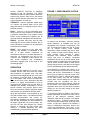
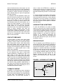
Weeder Technologies WTDIO-M various functions shown on the screen. You can then use the mouse to click on the Push Buttons and control the logic state of the channels which are setup for output, and hook up switches to those channels setup for input and experiment with their functions. order to allow the WTDIO-M to respond to multiple switch closures on a single I/O channel even though the typematic repeat delay for that particular channel may be set to a much slower rate. To set the typematic repeat delay of the buttons on a matrix keypad, work with the I/O channels which are setup for input (K-N). These channels correspond to the four columns of the keypad and may be set to different values if wishing to have certain button columns repeat at a different rate then others. To understand how this application works, first halt the run-loop by clicking on the red toolbar button at the top of the screen, then right-click on any screen object to pull up its properties dialog box. In this box you will be able to view the commands which the Push Buttons use to control the output channels, or view the input strings which the Event Counters and Event Timers watch for to control their operation. Channels G and H use conditional statements to detect a switch transition and send the appropriate message to their windows. To view or edit these conditional statements, go to the <Run-Loop> menu item at the top of the screen and click on <Conditionals>. Refer to the help files for more information. USING BUTTONS & SWITCHES To hook the WTDIO-M to a button or switch, simply run a wire from one contact of the switch to the desired I/O channel's screw terminal, and a wire from the opposite contact to the screw terminal labeled GND. A 10KΩ pull-up resistor is already included on the board for each I/O channel so no additional components are required. The logic level at the I/O channel will be high when the switch is open, and low when the switch is closed. CONTACT DEBOUNCE A typical switch or button uses metal plates (called contacts) which can be moved together or apart in order to make or break the current path. During switch closure, when these plates first make contact with each other they will bounce several times before coming to rest. This bouncing of the contacts will appear as multiple transitions to a digital system, and in most cases, not be desirable. DRIVING RELAYS The I/O channels of the WTDIO-M can sink or source only 25 mA. This current is insufficient to drive most relays therefore a switching transistor must be used as shown in Figure 2. The voltage applied to V+ should be that which is necessary to drive the relay and can be the same power source which is connected to the data module, or a completely separate supply as long as the ground terminals of the two supplies are tied together. Caution! DO NOT use the +5 volt output of the WTDIO-M as your relay power source. Each I/O channel of the WTDIO-M incorporates its own debounce timer used to mask these multiple transitions by disabling the input for a short period of time after each logic state change. When an I/O channel detects a change of state, the action is immediately reported to the host, its debounce counter is loaded with a time value equal to 100 mS, and the input is disabled until this time period has lapsed. Because each I/O channel's timer operates independently of each other, the WTDIO-M can still report actions on additional inputs while its waiting for one or more debounce timers to expire. FIGURE 2: HOOKING UP TO RELAYS V+ Relay coil 1N4001 To I/O Channel TYPEMATIC REPEAT 1K In addition to the debounce timers mentioned above, each I/O channel has its own typematic repeat timer which operates both independently of each other, and independent of its own debounce timer. The later being important in Copyright 2000-2008 by Weeder Technologies Page 6 2N2222 or equivalent Rev. K