1
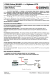
Apstar Limited In Control since 1988 GembusHub user manual Issue 001 8th June 2015 © 2015 Apstar Limited Unit 7 North Staffs Enterprise Centre Innovation Way Stoke on Trent ST6 4BF Phone: 01782 834177 Fax: 01782 838264 E‐mail: [email protected] Revision History: Revision 001 Page 2 Date 08/06/2015 Comment Initial Release GembusHub user manual 001 1. GembusHub Features 1.1 Gembus Control and monitor up to 400 Gemstarts Scan 400 Gemstarts in under 500ms RS485 ports x 4 for direct connection to Gemstarts Uses the native Gemstart protocol: Gembus Link speeds up to 115200 Configuration data for all 400 Gemstarts retained through a power down Full support for Group Data, Configuration Data, Broadcast commands, Group Control. Compatible with Gemstart 1 to Gemstart 5. 1.1.1 Ethernet 100Mbit Ethernet Interface Control and Monitor via Modbus TCP/IP Up to 16 Modbus TCP/IP simultaneous connections User defined IP address ranges for attached clients 1.1.2 USB Serial Modbus access via the USB port. 1.1.3 GembusHub GembusHub configuration settings retained through a power down One GembusHub at each end of the link can be used with one in control and the other in standby Gemstart configuration via Ethernet or USB Modbus interface Switchable termination resistors Diagnostic LED indications 2. GembusHub Control Ethernet Connector Unit ID: USB Connector Modbus TCP/IP Termination Resistors 12‐24V 0V Earth Power Connector Gembus Connections 1. Tx‐ 2. Tx+ 3. Scn 4. Rx+ 5. Rx‐ Termination DIP Switches 1.Tx 2.Rx Modbus RTU Power Gembus 1 Gembus 2 Gembus 3 Gembus 4 Serial link connectors Page 3 GembusHub user manual 001 2. GembusHub Operation The GembusHub is a fully functioning host for 4 links of Gemstarts with up to 100 Gemstarts on each link. An attached Modbus client, PLC or SCADA system, writes commands to the GembusHub which in turn are passed on to the attached Gemstarts. As the commands are sent out, the status of each Gemstart is read back into the GembusHub data map. The client system can read the status of each Gemstart at any time. The GembusHub presents data in two main forms: 1. General GembusHub data. This is data that is general to the unit or to all four Gembus links. It is available to a client device which should access this data by using Modbus messages to station ID 16. 2. Gembus link specific data. Four identical data areas are available for clients to read and write, each one being specific to one of the four Gembus links. The client must use the following station ID’s to access each area: Gembus Link 1: station 17 Gembus Link 2: station 18 Gembus Link 3: station 19 Gembus Link 4: station 20 Please refer to the Modbus data map for full details of the data structures that are available for client access. Station 16 General Data Area Station 17 Link 1 Data Area Station 18 Link 2 Data Area Station 19 Link 3 Data Area Station 20 Link 4 Data Area Read/Write Unit configuration data Read Gemstart Status Gemstart Load Gemstart Faults Link Statistics Read Gemstart Status Gemstart Load Gemstart Faults Link Statistics Read Gemstart Status Gemstart Load Gemstart Faults Link Statistics Read Gemstart Status Gemstart Load Gemstart Faults Link Statistics Write Start Commands Stop Commands Priority Commands Resets Write Start Commands Stop Commands Priority Commands Resets Write Start Commands Stop Commands Priority Commands Resets Write Start Commands Stop Commands Priority Commands Resets Read/Write Configuration Data Read/Write Configuration Data Read/Write Configuration Data Read/Write Configuration Data Page 4 GembusHub user manual 001 16 Modbus TCP/IP Clients (Max), each of which can access all of the data areas shown. 1 Modbus RTU Master, which can access all of the data areas shown. 3. Technical Specification PSU: Power: Weight: Mounting: Connectors: Ethernet: USB: 12 to 24V dc +/‐ 20%, 250mA 3W 600g DIN Rail or Surface Mount Phoenix MC1.5 Series (3.8mm pitch) connector: 3 way for PSU Phoenix MC1.5 Series (3.8mm pitch) connector: 5 way for Gembus 10/100Mbit RJ45 USB type B connector. Appears as a COM port on PC. Windows will need an .inf file for installation. Please download latest version from our web site. Page 5 GembusHub user manual 001 4. Connections Power Connector Pin 1 (left) 2 3 Description 12V to 24V dc 0V Earth for metal box 4.1 Gembus Connector The up to 100 Gemstarts are connected to the GembusHub via the 4 wire RS485 link. Wire GembusHub Tx to Gemstart Rx and wire + to +, ‐ to ‐. GembusHub GembusHub Gemstart Pin number Description Description 1 (left) Tx‐ Rx‐ 2 Tx+ Rx+ 3 Screen No connection 4 Rx+ Tx+ 5 Rx‐ Tx‐ 4.2 Termination The two ends of the link should be fitted with 120ohm termination resistors. Normally the GembusHub will be fitted to one end of the link. In this case the built in termination resistors should be turned on using the front panel dip switches. At the other end of the link from the GembusHub you should add a 120ohm termination resistor connecting Rx+ and Rx‐, and another resistor connecting Tx+ and Tx‐. Historically some networks were terminated with a 220ohm resistor to reduce the loading. Only use this if the 120ohm resistor causes communication errors. Rx+ Rx‐ Tx+ Tx‐ Add separate termination resistors or use a standby Gembus Hub Tx+ Tx+ Tx‐ Tx‐ GembusHub GembusHub Rx+ Rx+ Rx‐ Rx‐ Page 6 Rx+ Rx‐ Tx+ Tx‐ GembusHub user manual 001 4.3 Standby Operation On higher security installations a second GembusHub can be added to the link to provide a backup system. The best place to fit this is at the other end of the link from the primary GembusHub. This way the built in termination resistors can be turned on. When using two GembusHubs in the same link only one of the Hubs can be enabled at any one time. Set the Link Control register to 1 or 2 to enable transmission. The other GembusHub Link Control should be set to 0 to disable transmissions. In standby mode (Link Control set to 0) the Link Status register (512 or 1101) is still updated on the basis that if any data is received then another GembusHub must be talking to the Gemstarts to generate a reply. If no Gemstart replies are seen for 2s then the status flag is cleared to 0. Page 7 GembusHub user manual 001 5. LED indications 5.1 PSU LED LED Off 2 Red flashes Slow g‐y‐r cycle Green On Description No power Power from USB only. No Gembus functionality USB connected (GembusHub powered from 12‐24V supply) Healthy 5.2 Gembus LEDs LED Off Description Link disabled (no transmissions). Not receiving any data which suggests nothing is communicating with any Gemstart OR running on USB power only which does not support Gemstart comms 2 Green Flashes Link disabled (no transmissions). Still receiving data which suggests another GembusHub is communicating to the Gemstarts. Red On Transmitting and no Gemstarts in the scan range are replying Yellow On Transmitting and some Gemstarts in the scan range are replying Green On Transmitting and all Gemstarts in the scan range are replying Slow Green Flash Gemstart Simulator is seeing valid messages replying Slow Red Flash Gemstart Simulator configured but is not seeing any valid messages 5.3 Network LED LED Off 2 Red flashes 3 Red flashes 4 Red flashes 5 Red flashes 2 Yellow flashes Green Description IP Hardware not initialised yet Not seen the network yet (cable not plugged in since power on) Network cable removed (cable was plugged in but now removed) DHCP not found IP address not allocated No Modbus messages within timeout period Receiving Modbus messages within timeout period 5.4 Network Connector Left LED Off Green Right LED Off Yellow Page 8 Description No link Good link Description No activity Link Activity (NB Not necessarily to this device) GembusHub user manual 001 5.5 LED Testing Register 207 can be used to test all 8 LEDs without affecting the functionality of GembusHub. To test write the following values in to register 4x207: Value Result 0 Testing not active, normal operation results. 1 All six status LEDs are switched to green 2 All six status LEDs are switched to red 3 All six status LEDs are switched to yellow 4 All six status LEDs are switched to cycle through colours Page 9 GembusHub user manual 001 6. Control Timing The time it takes for a command to be actioned and confirmed is dependant on a number of factors. Reference Description Command Update time This is the time it takes the SCADA system to get round to sending the new command. This is under the control of the SCADA system. Modbus TCP/IP time In tests up to 400 Modbus TCP/IP messages can be processed per second by the GembusHub. So factor in a delay of around 2ms to actually send the Modbus TCP/IP message. Gemstart Slot time This is the time it takes for the GembusHub to send a message and get a reply from one Gemstart. This depends on the size of the message. See the table below for example Gemstart Slot times. Command Broadcast time The fastest way to get the new command out to the Gemstart is to enable Broadcast Mode. If this is enabled then the longest time possible is 2 Gemstart Slots (see above) Gemstart Action Delay This is the time it takes for the Gemstart to react to the broadcast or standard command once it has received it. Less than 5ms. Contactor Open/Close Delay The reaction time of the contactor. Typically this is 13 to 20ms Gemstart Detection Delay The time for Gemstart to detect that the contactor has opened. Typically this is 20ms GembusHub Scan Time The time it takes for the GembusHub to read back that the contactor has closed. This is probably the longest delay in the sequence and is equal to the scan time for the link. The scan time is equal to the number of Gemstarts in the scan plus 1, times the slot time. SCADA poll delay The time between reads performed by the SCADA system 6.1 Gemstart Slot and Scan Times The times are the milliseconds per Gemstart in the scan range. Ie for a scan of 0 to 99 multiply these figures by 100. To calculate the scan time add 1 to the number of Gemstarts in the scan and multiply it by the Gemstart Slot time. Eg for a scan range of 100 Gemstarts at 19200 and normal status then the scan time will be about (100 + 1) * 4.2 = 424ms Gemstart Slot times in ms. Control Number of 9600 19200 38400 57600 115200 Code Registers read Normal Status 0 2 8.5ms 4.2ms 2.2ms 1.5ms 0.8ms Short Status 1 1 6.4ms 3.2ms 1.6ms 1.1ms 0.6ms Long Status 2 3 10.6ms 5.3ms 2.7ms 1.8ms 0.9ms G10 Status 3 8 22.0ms 11.0ms 5.5ms 3.7ms 1.9ms 6.1.1 Example For G10 Status from 100 Gemstarts at 19200 the send and confirm time is: Modbus + Gembus Broadcast + Action Delay + Contactor Time + Detection Delay + Scan Time = 2 + 2*11 + 5 + 15 + 20 + 101*11 = 1175ms This can be improved by using a faster baud rate, smaller scan range or smaller status message. Page 10 GembusHub user manual 001 7. USB The USB port allows local access to the GembusHub data map. The port can also be used to see diagnostic information generated by GembusHub. See the Data Map document for a description of how to access the diagnostic data. 7.1 USB Installation Connect the GembusHub to the PC using the USB connector. If the PC tries to install the driver then point it to the relevant inf file which can be found in https://www.dropbox.com/sh/anng3leype1n2wx/AAD‐TeEGRr1‐ p7hdpiirwROna?dl=0 and follow the installation instructions. Once installed look in the Device Manager / Ports section to see which com port has been allocated to “Apstar GembusHub WinX Driver”. 8. USB Diagnostics Text based debug and diagnostics messages can be accessed via the USB port. These messages can be “turned on” from a windows terminal program (such as SimpleDiagnostics) by typing a question mark ‐ ?. Disconnecting the Terminal Window and connecting to a Modbus terminal again will disable the diagnostics. This is essential information to locate any problems that may arrive. Make sure the Modbus driver and the reprogramming application are not connected to the USB port. Get SimpleDiagnostics from the dropbox: https://www.dropbox.com/sh/anng3leype1n2wx/AAD‐TeEGRr1‐p7hdpiirwROna?dl=0 Start it up and set the com port to that allocated to the “Apstar GembusHub WinX Driver”. Set GembusHub USB Port checkbox on. Click Connect. Useful options are: Timestamp Log to Disk Auto Connect Once Simple diagnostics has connected to the GembusHub, enter “?” without the quotes and enter. This enables the diagnostics. Up to 8K of diagnostics history will be downloaded. Sometimes you have to enter the ? twice. Page 11 GembusHub user manual 001 9. Reprogramming Make sure you have disconnected your Modbus application and that Simple Diagnostics is also disconnected from the USB port. Get the latest GHubV1‐60‐xx‐xx.exe file from Apstar. Run the exe file Device Connected If it doesn’t say it’s connected then double check nothing else is connected to the GembusHub Version Info It tells you which version is in the device and which version you are about to reprogram it with. Update GembusHub Click Single Auto Wait for Completion Once the Device Updated text appears the device has been updated. Disconnect the USB lead and the update program will auto close. Page 12 GembusHub user manual 001 10. Remote Reboot Sometimes it is useful to be able to remotely reset the GembusHub, eg after changing the Modbus TCP/IP Port setting which is only used during startup. A remote reboot can be actioned by writing “REBOOT” to the time setting registers with a single multi register write to 6 registers ie Write Address: 100 Write Length: 6 registers Register 100: 82 (Ascii R) Register 101: 69 (Ascii E) Register 102: 66 (Ascii B) Register 103: 79 (Ascii O) Register 104: 79 (Ascii O) Register 105: 84 (Ascii T) There will be no reply to this message and the GembusHub will immediately reboot. Comms to the Gemstarts will stop for about 2.7s. Page 13 GembusHub user manual 001