1
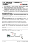
MINICV
micro MIDI-2-CV device
USER MANUAL
Roman Sowa 2013
www.midimplant.com
1.
Overview
Thank you for choosing MINICV as your new MIDI2CV converter. This short manual will guide
you through installation, and available settings.
The board was designed to be mounted where no other converter would fit, most likely hand
held battery operated instruments and noise boxes, but also directly on VCO boards of analog
synths. No mounting holes are provided, only a few soldering pads in narrower than usual 2mm
spacing. The connecting wires are enough to secure it in place, as it weighs less than 1 gram.
There's 1 analog output, capable to control analog synths with V/oct scaling. MINICV comes
factory set to 1V/oct scale (at 100k load) responding to MIDI channel 1 with "C" as lowest key.
The CV can be reassigned to different type of MIDI event, not only keyboard notes - this is
described in chapter 5.
The device requires only one (positive) power supply. Simple setup, like assigning channel and
starting note, can be done with MIDI-learn button. More options are accessible via MIDI System
Exclusive commands. All user settings are memorized in nonvolatile memory, taking power off
does not reset anything to defaults, the settings are kept as they were last entered.
MINICV board described here is a product of:
"MIDI-hardware" Roman Sowa, ul. Azotowa 15B, 41-503 Chorzów, Poland
phone +48 532 425 835, email [email protected]
© 2013, Roman Sowa
made in Poland, EU
manual edition 6
2.
Layout
Picture below explains all connections in MINICV board.
They are:
● MIDI input (1-2)
● MIDI pass-thru output (3)
● Gate output (4)
● MIDI-learn input (5)
● CV output (6)
● GND (7)
● Power supply (8)
The board has no holes for mounting screws. It can be soldered to synth circuit as additional
component - it's the size of integrated circuit and can use leading wires as support, like SIP.
MIDI IN signal (DIN socket pins 4 and 5) should be connected to pads 1 and 2 as indicated in
the picture. Polarity does not matter. Middle pin of DIN socket, number "2", must not be
connected anywhere, it must be left open to comply with MIDI specification.
In the upper right corner there's tiny trimmer for fine tuning the V/oct ratio. Its tuning ratio
depends on V/oct scale and resistance of connected CV input. At typical 100k load and 1V/oct
scale it has a full turn range of about +/-5 mV/oct.
1.
Power supply
Make sure that all leading wires are as short as possible, especially the one connecting GND
(ground, 0V potential). The best way to place the module is inside VCO circuit, or at the "star
ground" in power supply, where tuning reference point can be easily found. The quality of
ground connection directly affects the quality of generated Control Voltage. MINICV is designed
to work with supply voltages commonly found in synths. It requires only one supply, from +5V
to +15V. Current drawn is about 1mA. Power input must be DC. Connecting AC power, or
reversing the power leads will immediately damage the board.
2.
Connections
2.1. CV output
CV output has adjustable resistance, so any scale select and fine tuning should be done after all
connections are in place. At 100k load it gives +/- 5mV/oct tuning range. Larger changes are of
course possible with Sys-Ex settings, from 0.05V/oct up to insane values of several volts per
octave. If CV input resistance of your VCO is lower, fine tuning range increases, for example at
20k it's +/- 25mV/oct.
The range of CV output is user selected between 2 levels. Default is 4-octave range and 0-4V
output. This one is well regulated and does not change with temperature or supply voltage. It is
primarily intended to use as CV source for VCOs. The other CV range is 5 octaves and 0-5V. It
can be used for applications where precision is not a must, like modulation, drum trigger etc.
This range is not so well regulated, it may slightly change with temperature and supply voltage,
although the change is minimal enough to use in most applications without noticing.
CV can work also in reverse, giving full voltage at lowes note, and 0V at top note. This can
sometimes greatly simplyfy MIDIfication of instrument, when it's easier to have it in reverse.
This is configured by Sys-Ex only.
The CV output can respond to one of several MIDI events. They are:
● Note on/off
● Note velocity
● Pitch Bend
● Continuous Controller
● Program Change
● Channel After Touch
● Polyphonic After Touch
Control Voltage goes down to 0V and reaches up to 4 or 5V depending on selected range. It
makes 49 or 61-note range for 1V/oct scale. If CV is configured as MIDI event different than
notes, 0V represents lowest MIDI value, and 4V or 5V is output when highest MIDI value is
received.
All MIDI events other than notes are represented in voltage as one of 128 levels, except Pitch
Bend, working with much better resolution. Neutral position of Pitch Bender is half of the
selected voltage range at CV output.
For note on/off, CV scale can be adjusted in wide range, from 0.05 to about 2V/oct. If the scale
is higher than 1V/oct, there is of course no room for 61 notes in 5V range (or 49 notes in 4V
range), so actual usable range is limited by highest achievable voltage. Every note higher than
that gives maximum available voltage (4 or 5V selected).
2.1. Gate output
Gate output is push-pull type (meaning it can source and sink current) with 5V active state and
1k output resistance. Gate polarity can be reversed by settings (+5V for note off and 0V for
note on) - it may be useful in some synths or if you want to achieve higher gate voltage with
single external transistor. Also it is useful in S-trigger circuit requiring only one external
transistor.
The Gate pulses voltage indicating the duration of MIDI note. When MINICV is configured to
respond to MIDI notes, gate output remains at 0V until any note from valid range is played. It
then goes up to +5V, and stays there until all notes get released. It is typical V-trigger mode. In
all other events configured, Gate output remains at 0V. It is possible to enable retrigger
function, so gate will go off for very short pulse between notes. The gap is enough to retrigger
envelope in most synths.
To have S-trigger mode, you may add single transistor. Base to Gate output (you may add 20k
resistor before the Base), Emitter to GND, and Collector is your S-trigger gate.
2.2. MIDI THRU output
MINICV repeats all incoming MIDI data at "THRU" output. To connect DIN socket compliant
with MIDI standard for MIDI-THRU output, connect the "thru" pad of MINICV to pin 5 of DIN
socket. Add 220ohm resistor between pin 4 of DIN socket and +5V that must be taken from
somewhere outside MINICV.
MIDI pass-thru output is not actually typical MIDI-THRU found in most instruments. It
regenerates input signal, so you can chain limitless number of MINICV boards without problems
that would normally occur in regular long MIDI-THRU chains. Unfortunately it introduces a short
delay of about 0.3ms, so practical limit for number of chained devices is about 20-50 until the
latency of last unit will be noticeable or annoying, depending on attack time of the sound.
2.3. MIDI-learn input
MIDI-learn is an input for optional momentary switch for setup basic operation: MIDI channel,
event, and starting note if the event is note on/off. To use learn mode, short this input
momentarily to ground, and the first MIDI data received will become the one that MINICV will
respond to afterwards. MIDI events possible to set this way are all listed in chapter 4.1.
3.
User settings
After successful installation, you can set up the MIDI event, CV range and gate polarity. To do
so, your synth must be powered on and you need the MIDI-learn button connected or have any
kind of Sys-Ex editor. There are 6 parameters to set:
1. MIDI channel and event for CV/gate
2. V/oct scale tune
3. CV voltage range (4 or 5V)
4. Gate polarity
5. CV polarity
6. gate retrigger
Only the first setting (channel and event) can be done both ways, via MIDI-learn button or SysEx. All other ones are accessible via Sys-Ex only.
The System Exclusive command's structure is as follows:
Sys-Ex header (F0), manufacturer ID (00 20 7A), device ID (02), command (01-08), related
parameters and Sys-Ex footer (F7). This is described in details here. All numbers are
represented in hexadecimal format. You may use any kind of Sys-Ex editor to send those
commands to MINICV.
3.1. Channel and event
Channel and event can be set by MIDI-learn button, or Sys-Ex. For example to make MINICV
respond to your keyboard, push the MIDI-learn button momentarily, and play the lowest note.
Same thing if you want to assign Pitch Bend or other MIDI parameter - push the button, and
move the MIDI controller.
The same settings via System Exclusive:
F0 00 20 7A 02 01 <channel> <event> <param> F7
where <channel> parameter is MIDI channel number in range 1-16 (01-10 in hex).
Table below describes meaning of both remaining parameters:
<event>
MIDI event type
meaning of <param>
01
Note on/off
starting note
02
Polyphonic Aftertouch
ignored
03
Continuous Controller
CC number (00-7Fh)
04
Program Change
ignored
05
Channel Aftertouch
ignored
06
Pitch Bend
ignored
10h
drum trigger mode
note number (00-7Fh)
In drum trigger mode (available only via SysEx) MINICV responds to only one note, so several
MINICVs can create multiple drum triggers in one channel. If assigned note comes in, GATE
output goes active for entire duration of the note selected in <param>, and CV outputs its
Velocity.
3.2. V/oct scale tune
F0 00 20 7A 02 02 <tune> F7
where <tune> is determining amount of voltage per one octave. Possible values are 00-7Fh.
Tuning can be set in steps of 12.5mV/oct in 4V range and about 15.5mV/oct in 5V range.
Normal 1V/oct scale is achieved when <tune> is 40 (hex) for 4V range and 30 (hex) for 5V
range.
Tuning affects only note on/off. Any other events always use full voltage range.
3.3. CV range select
F0 00 20 7A 02 03 <range> F7
where <range> takes only one of 2 possible values: "01" sets 4V, 4-octave range, and "02" sets
5V, 5-octave range. This also affects maximum voltage for all MIDI events other than notes.
Please bare in mind that 5V range is not guaranteed to be precision and particularly stable.
3.4. GATE polarity reversal
F0 00 20 7A 02 04 <polarity> F7
where <polarity> determines how active note is indicated at Gate output. If <polarity> is "00",
note on means +5V and note off 0V. If <polarity> is "01", note on means 0V, and note off is
+5V.
3.5. CV polarity
F0 00 20 7A 02 07 <polarity> F7
where <polarity> determines how the voltage changes depending on note received. When
<polarity> = 00, CV outputs 0V at lowest note and 4V or 5V (see 5.3.) when the highest note
was played. When <polarity> = 01, CV is 4V or 5V at lowest note and 0V when the highest
note was played.
3.6. Retrigger mode
F0 00 20 7A 02 08 <retrig> F7
where <polarity> determines if there should be retriggering pulses between notes. When
<retrig> = 00, playing legato results in flat Gate signal. When set to 01, gate will go off for
very short pulses at the beginning of each note in legato group.
3.7. Factory defaults
Send this Sys-Ex sequence to MINICV to go back to default settings:
F0 00 20 7A 02 01 01 01 24 F7
F0 00 20 7A 02 02 40 F7
F0 00 20 7A 02 03 01 F7
F0 00 20 7A 02 04 00 F7
F0 00 20 7A 02 07 00 F7
F0 00 20 7A 02 08 00 F7
The above Sys-Ex commands must not be sent immediately one by one, make sure to add at
least 10ms delay between each line.
MINICV is configured then as follows:
● note range C2-C6 (36-84 in MIDI note numbers)
● channel 1
● 4V precision voltage range, 0V at C2, 4V at C6
● 1V/oct scale (assuming 100k load at CV output)
● positive gate (off 0V, on 5V) without retrigger