1
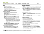
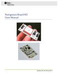
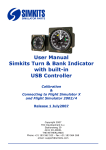
Installation Instructions
IN
Allen-Bradley
1397
Regulated Field Supply Card
Cat. Nos. 1397-FS2004
1397-FS2010
1397-FS2015
Table of Contents
What This Option Provides . . . . . . . . . . . . . . . . . . . . . . . . . . . . . . . . . . . . . . . . 1
Where This Option Is Used . . . . . . . . . . . . . . . . . . . . . . . . . . . . . . . . . . . . . . . . 1
What These Instructions Contain . . . . . . . . . . . . . . . . . . . . . . . . . . . . . . . . 1
How This Option Works . . . . . . . . . . . . . . . . . . . . . . . . . . . . . . . . . . . . . . . . . . . . 2
How to Select a Regulated Field Supply . . . . . . . . . . . . . . . . . . . . . . . . 4
Installation . . . . . . . . . . . . . . . . . . . . . . . . . . . . . . . . . . . . . . . . . . . . . . . . . . . . . . . . . . 5
Setup . . . . . . . . . . . . . . . . . . . . . . . . . . . . . . . . . . . . . . . . . . . . . . . . . . . . . . . . . . . . . . . . . 13
What This Option
Provides
When installed, the Regulated Field Supply Card enables the drive’s
software field control loop, allowing field control functions to be
adjusted by the user.
Where This Option Is
Used
This option may be used with all 1397 Drives.
What These Instructions
Contain
Catalog
Number
Regulated
Field Supply
Amp Rating
1397-FS2004
1397-FS2010
1397-FS2015
4A
10A
15A
These instructions contain the necessary information to install and
configure a 1397 Regulated Field Supply Card. For additional
information on parameter programming, field supply operation and
function block diagrams, refer to the 1397 User Manual —
Publication 1397-5.0.
1397 – 5.17
September, 1997
2
1397 Regulated Field Supply Card
How This Option Works
P.044
[Motor Field Amps]
Field Current Regulator
P.175
[Fld Econ Active]
HI
P. 280
[Field Reference]
P.279
[Fld Loop Kp]
P.176
[Field Ref TP]
P.278
[Fld Lp Lead Freq]
P.174
[Field Delta]
KP WLD
OFF
LO
+
ON
0
P.044
[Motor Field Amps]
FIELD PHASE
FIRING LOGIC
PI Block 1
–
LO
FIELD
REGULATOR
SUPPLY
HI
GAIN
P.010
[Field Feedback]
MUL DIV
100
P.274
[Fld Econ Ref]
0°
FIELD
SOFTWARE
SCALING
A/D
GAIN
CURRENT
MUL
FEEDBACK
P.281
[Fld Loop K-Fdbk]
P.044
[Motor Field Amps]
Armature Voltage Regulator
P.284
[Field Weaken Level]
P.045
[Motor Arm Amps]
+
+
LO
HI
PI Block 2
–
–
+
P.283
[Field Weaken KP]
P.276
[Fld Delta Hi Lim]
1 P.275 [Fld Auto Weak] is clamped to Disabled when
P.039 [Feedback Type] = P.005 [Armature Voltage].
ABS
–
VOLTAGE
ENABLED
DISABLED
P.282
[Fld Weak Ld Freq]
ARMATURE
1
P.275
[Fld Auto Weak]
KP WLD
SOFTWARE
SCALING
P.066
[IR Compensation]
P.006
[Cur Loop Fdbk]
P.276
[Field Delta Hi Lim]
Field Control Loop Parameters
SOFTWARE
SCALING
(8-Sample Average)
P.066
[IR Compensation]
P.044 [Motor Field Amps]
P.045 [Motor Arm Amps]
P.066 [IR Compensation]
P.273 [Fld Econ Delay]
P.274 [Fld Econ Ref]
P.275 [Fld Auto Weak]
P.276 [Fld Delta Hi Lim]
P.277 [Fld Loss Level]
P.278 [Fld Lp Lead Freq]
P.279 [Fld Loop Kp]
P.280 [Field Reference]
P.281 [Fld Loop K-Fdbk]
P.283 [Fld Weaken Kp]
P.284 [Fld Weaken Level]
For the drive to operate, one of the following field supply
options must be present.
• A Fixed Field Supply
• A Regulated Field Supply
• An Enhanced Field Supply
At power-up if the Regulated Field Supply Card is installed:
1. P.177 [Field Regulator] will detect it’s presence and display
either 4, 10 or 20A — the Regulated Field Supply Card’s
rating.
2. The field current control loop shown above operates and
drive parameters P.184 [J20 Fld Loss Det], P.185 [J21 Field
Supply] and P.272 [E-Fld Volts Adj] are ignored.
3. The Regulated Field Loss and Field Economy circuits
become active in place of those used by the Fixed and
Enhanced Field Supply options.
1397 – 5.17
September, 1997
1397 Regulated Field Supply Card
Important: The Regulated Field Supply Card will not regulate field
current until a valid value for parameter P.044 is entered. The drive
can be operated however, when the Regulated Field Supply Card is
operating in the fixed voltage mode. Field loss detection will only
occur if there is a complete loss of field current. This is similar to
having the Fixed or Enhanced Field Supply installed.
The Field Control Loop contains (2) regulators — A Field Current
Regulator and an Armature Voltage (or counter-EMF) Regulator.
ARMATURE VOLTAGE
FIELD CURRENT
LD
FIE
CU
RR
AG
E
100%
of FIELD CURRENT
or ARMATURE VOLTAGE
VO
LT
EN
AT
UR
E
0%
of FIELD CURRENT
or ARMATURE VOLTAGE
T
W
EA
KE
NI
NG
M
(continued)
The field control loop can operate in one of two ranges — A
Constant Torque (armature control) Range or a Constant HP (field
control) Range.
If the Regulated Field Supply Card’s factory defaults are set, it will
operate in a fixed voltage mode by firing the field SCRs at a fixed
angle of 117°. This will produce a motor field voltage of 150V DC
with a 230V AC line input, or 300V DC with a 460V AC line input.
To produce other motor field voltages, parameter P.044 [Motor Field
Amps] must be set as described in the Setup section of this
publication before motor startup. Even though the Regulated Field
Supply will be producing fixed voltage, the value of parameter P.044
will be set to 0.01 Amps. After a valid value is entered for P.044, the
user-assigned value for parameter P.277 [Fld Loss Level] becomes
effective.
AR
How This Option Works
3
CONSTANT TORQUE
CONSTANT HP
TOP SPEED
BASE SPEED
As shown above, in the Constant Torque (armature control) range, the
Field Control Loop can be configured to decrease Armature Voltage 1
when the motor’s armature is greater than P.284 [Fld Weaken Level] and
the field begins to weaken. As motor speed increases beyond base
speed, Armature Voltage will increase above rated voltage. PI
(proportional plus integral) Block 2 monitors armature voltage and
will reduce the HI limit of PI Block 1 that controls field current. As
field current decreases, field flux and Armature Voltage also
decreases. Field current continues to decrease until Armature Voltage
is equal to the value set in P.284 [Fld Weaken Level].
1 The armature IR drop can be compensated for by resetting parameter P.066 [IR Compensation].
1397 – 5.17
September, 1997
4
1397 Regulated Field Supply Card
How This Option Works
(continued)
Control of Armature Voltage during field weakening can only occur
when a tachometer or encoder is used and P.039 [Feedback Type] is not
set to Arm Volt. Field weakening can also be disabled by setting P.275
[Fld Auto Weak] to Disabled. The drive can also be operated in the
Constant HP (field control) Range, controlling parameter P.280 [Field
Reference] exclusively.
Both the Field Current Regulator and the Armature Voltage Regulator
contain Proportional plus Integral (PI) control. There is no user
configurable low limit parameter setting to these PI blocks. The low
limit is always fixed at 0°. The high limit however, can be set up to
180° delta using parameter P.276 [Fld Delta Hi Lim]. This input allows a
full-on field voltage of 207V DC with a 230V AC line input, or 414V
DC with a 460V AC line input. To regulate higher field voltages, a
step-up transformer must be used to supply the AC side of the field
supply bridge. The output of the Field Current Regulator is an angle
to the regulated field supply gate firing circuit represented in degrees
by parameter P.174 [Field Delta].
How to Select a
Regulated Field Supply
There are (3) Regulated Field Supply Cards to select from — 4, 10
or 15 Amps. Each Regulated Field Supply Card provides (3) different
gains for field current feedback — 1, 2 or 5.
When the Regulated Field Supply Card is installed, at Drive Setup,
the 1397 User Manual instructs the user to enter the rated hot field
amps from the motor’s nameplate into parameter P.044 [Motor Field
Amps]. Once this value has been entered, the software will
automatically select the feedback gain from the board to produce the
largest full scale digital value in the A/D converter. P.044 will be
limited to a value based on the Regulated Field Supply Card installed.
Important: Select the kit that provides the motor’s nameplate hot
field current — Including any current necessary for field forcing —
Required by your application.
Catalog
Number
1397 – 5.17
September, 1997
Regulator P.044
Rating
Value
Rated
Gain Output Amps
Field Current
Resolution
1397-FS2004 4A
0.11-0.8A
0.81-2.00A
2.01-4.00A
5
2
1
0.8A
2A
4A
4mA
10mA
20mA
1397-FS2010 10A
0.28-2.00A
2.01-5.00A
5.01-10.00A
5
2
1
2A
5A
10A
10mA
25mA
50mA
1397-FS2015 15A
0.55-4.00A 5
4.01-10.00A 2
10.01-20.00A 1
4A
10A
15A
20mA
50mA
100mA
1397 Regulated Field Supply Card
Installation
!
!
5
ATTENTION: This board contains ESD (Electrostatic
Discharge) sensitive parts and assemblies. Static control
precautions are required when installing, testing, servicing
or repairing this assembly. Component damage may result if
ESD control precautions are not followed. If you are not
familiar with static control procedures, reference publication
8000-4.5.2, “Guarding against Electrostatic Damage” or any
other applicable ESD protection handbook.
ATTENTION: Electric Shock can cause injury or death.
Remove all power before working on this product.
The drive is at line voltage when connected to incoming AC
power. Before proceeding with any installation or
troubleshooting activity, disconnect, lock out, and tag all
incoming power to the drive. Verify with a voltmeter that no
voltage exists at terminals L1, L2 and L3 on the drive input
power terminal block.
❏ 1 Remove and lock-out all incoming power to the drive.
❏ 2 For 1.5-30HP/230V and 3-60HP/460V Drives, loosen the (2)
captive thumb screws to remove the drive cover.
Captive
Thumb
Screw
Captive
Thumb
Screw
1.5-30HP/230V and 3-60HP/460V Drives
with Drive Cover in Place
1397 – 5.17
September, 1997
6
1397 Regulated Field Supply Card
Installation
(continued)
❏ 3 For 1.5-30HP/230V and 3-60HP/460V Drives, loosen the
captive carrier retaining screw to swing the carrier door open.
Captive
Carrier
Screw
1.5-30HP/230V and 3-60HP/460V Drives
with Carrier Door Closed
❏ 4a For 40-60HP/230V and 75-125HP/460V Drives without an AC
line disconnect, loosen the (2) auxiliary panel cover retaining
screws. To lift out the auxiliary panel, loosen the screws only
enough to allow the panel tabs to slide out.
45
A1
GRD
Panel
Tab
Retaining
Screw
S4
S4
S4
P4
P4
P4
Panel
Tab
Retaining
Screw
181
182
183
40-60HP/230V and 75-125HP/460V Drives
with Auxiliary Panel Cover
1397 – 5.17
September, 1997
1397 Regulated Field Supply Card
7
Installation
(continued)
45
❏ 4b For 40-60HP/230V and
75-125HP/460V Drives with
an AC line disconnect, both
the disconnect switch and
disconnect panel must be
removed.
AC
AC
Line Disc.
Line Disc.
Mounting
Mounting
Screw
Screw
81
82
83
A1
A1
GRD
DANGER
810903-2424
CIRCUIT BREAKER DOES NOT DISCONNECT INCOMING A0P4
LINE POWER IT ONLY PROVIDES DC FAULT PROTECTION. P4
S4
S4 PAS L'AUTOMENTATION DU SPOTEUR IL NESP4
LE DISCONECTEUR NE COUPTE
SERT QUE A ASSURER UNES4
PROTECTION CONTRE LES DESFAULTS DC.
ON
AC
Line Disc.
Mounting
SET AT "2"
Screw
OFF
AC
Line Disc.
Mounting
Screw
47
To remove the disconnect
switch from the disconnect
panel:
• Remove the (3) bus bar
1 ⁄ 4”(250A disconnect) or
3 ⁄ 8”(400A disconnect)
fasteners.
• Remove the (4) AC line
disconnect mounting screws.
To remove the disconnect
panel:
• Remove the (2) disconnect
panel tab screws to free the
tabs.
• Remove the top and bottom
disconnect panel retaining
screws.
• Loosen the middle
disconnect panel retaining
screw to slide out the
disconnect panel for
removal.
Bus Bar
Fastener
Bus Bar
Fastener
Bus Bar
Fastener
40-60HP/230V and 75-125HP/460V Drives
with AC Line Disconnect
45
Disc.
Panel
Tab
Screw
A1
81
82
83
Disc.
Panel
Retaining
Screw
GRD
Disc.
Panel
Tab
Screw
S4
S4
S4
P4
P4
P4
Disc.
Panel
Retaining
Screw
Disc.
Panel
Retaining
Screw
40-60HP/230V and 75-125HP/460V Drives
with AC Line Disconnect Removed
1397 – 5.17
September, 1997
8
1397 Regulated Field Supply Card
Installation
(continued)
❏ 5 To remove either the Fixed or Enhanced Field Supply, remove
the (4) retaining screws from the outside right side panel.
Retaining
Screw
Retaining
Screw
Retaining
Screw
Retaining
Screw
1.5-30HP/230V and 3-60HP/460V Drives
— Outside Right Side Panel —
Retaining
Screw
Retaining
Screw
Retaining
Screw
Retaining
Screw
40-60HP/230V and 75-125HP/460V Drives
— Outside Right Side Panel —
1397 – 5.17
September, 1997
1397 Regulated Field Supply Card
9
Installation
❏ 6 Unplug the (5) blue fast-on connectors from the Fixed or
Enhanced Field Supply Card.
• For 1.5-30HP/230V and
J6
3-60HP/460V Drives, unplug
the red P4 connector from the
Power Interface Board to free
F2/35
the card.
582
• For 40-60HP/230V and
75-125HP/460V Drives,
unplug the red P4 connector
from Power Interface Board
Regulated
connector S4 to free the card.
583
Short
Field
1
58
Wire
Supply
Harness
Card
F1/37
❏ 7 Remove the (4) retaining
screws from the back of the
Regulated Field Supply
FLD
Card. Use these same (4)
FLD P3
FLD P3
P3
screws to install the
Regulated Field Supply card
in the Fixed or Enhanced
J3
Field Supply Card’s old
location. Plug either the
shorter or longer wire
harness included with the
kit into the Regulated Field
1.5-30HP/230V and 3-60HP/460V Drives
Supply Card and reattach
— Inside Right Side Panel —
the (5) blue fast-on
connectors as shown.
FLDP6
FLDP6
FLDP6
J7
J4
37
F1+
7J
4J
3J
8J
185
73
+1F
J3
C/R
385
2J
1J
285
6J
5J
13-91785
53
–2F
J8
581
R/C
583
J2
J1
582
J6
J5
58719-31
35
F2–
(continued)
FLDP6
FLDP6
FLDP6
Long
Wire Harness
P3
FLD P3
FLD P3
FLD
58719-31
583
581
J8
J2
J6
J3
37
F1+
582
J4
J1
583
581
583
58719-31
35
F2–
582
37
F1+
F1/37
J6
582
R/C
J3
J8
J2
J6
J7
J5
581
J3
J4
F2/35
Regulated Field Supply Card
40-60HP/230V and 75-125HP/460V Drives
— Inside Right Side Panel —
1397 – 5.17
September, 1997
10
1397 Regulated Field Supply Card
Installation
❏ 8a For 1.5-30HP/230V and 3-60HP/460V Drives, route the other
end of the wire harness through the drive carrier along the
bottom of the drive chassis as shown. Secure the wire harness
to the drive chassis using cable ties included with the kit.
(continued)
81
82
83
REG
P25
Regulated
Field Supply
Card
Regulated
Field Supply
Wire
Harness
— Carrier Door Open —
— Carrier Door Open —
1.5-30HP/230V and 3-60HP/460V Drives
❏ 8b For 40-60HP/230V and 75-125HP/460V Drives, route the
other end of the wire harness through the drive carrier along the
top of the drive chassis as shown. Secure the Regulated Field
Supply wire harness to the existing drive wire harness using
cable ties included with the kit.
Regulated
Field Supply
Wire
Harness
REG
P25
P4
P4
P4
Regulated
Field Supply
Card
— Carrier Door Open —
1397 – 5.17
September, 1997
— Carrier Door Closed —
40-60HP/230V and 75-125HP/460V Drives
1397 Regulated Field Supply Card
Installation
(continued)
11
❏ 9 Plug the other end of the Regulated Field Supply wire harness
into Regulator Board connector J25.
J25
REG
P25
1.5-30HP/230V and 3-60HP/460V Drives
— Carrier Door Closed —
45
A1
GRD
J25
S4
S4
S4
P4
P4
P4
REG
P25
181
182
183
40-60HP/230V and 75-125HP/460V Drives
— Carrier Door Closed —
1397 – 5.17
September, 1997
12
1397 Regulated Field Supply Card
Installation
❏ 9 Replace fuses 6FU, 7FU & 8FU with the (3) UL Class
CC/600V/25A fuses included with the kit.
(continued)
1.5-30HP/230V and 3-60HP/460V Drives
6FU 7FU 8FU
Top
6FU
7FU
8FU
40-60HP/230V and 75-125HP/460V Drives
Top
1397 – 5.17
September, 1997
1397 Regulated Field Supply Card
13
Installation
(continued)
❏ 10 If required, reinstall the auxiliary panel cover or AC line
disconnect removed in steps 4a & 4b. Torque the (3) bus bar
fasteners to the values listed below.
Fastener Size
1 ⁄ 4”
3 ⁄ 8”
Setup
Maximum Torque
7.46 N-m (66 lb.-in.)
26.66 N-m (236 lb.-in.)
The following parameters are grouped by Regulated Field Supply
Card function. Depending upon the application, not all parameters
must be changed from the parameters’ default settings. Parameter
P.044 [Motor Field Amps] however, must always be reset to accommodate
the Regulated Field Supply Card.
Field Loss Parameters
P.044 [Motor Field Amps]
P.274 [Fld Econ Ref]
P.277 [Fld Loss Level]
When the Regulated Field Supply is operating in the fixed voltage
mode, field loss detection will only occur if there is a complete loss
of field current.
When the field current regulator is controlling field current, and the
Regulated Field Supply Card is not operating in the fixed voltage
mode, a field current loss fault will be generated when the field
current drops below the value set for parameter P.277 [Fld Loss Level].
The same field feedback signal used by the Regulated Field Supply
Card is used by the field loss detection circuit. Field current feedback
is compared against the value entered in parameter P.277 [Fld Loss Level].
If feedback < P.277, a fault will be generated. P.277 is entered as a
percentage of parameter P.044 [Motor Field Amps]. P.274 [Fld Econ Ref] must be
set > P.277 [Fld Loss Level] to avoid field loss faults.
A field loss fault will also occur if the digital value on the A/D
converter reaches full scale — Approximately 28% above the rated
field output.
Important: Regulator Board Jumper J20 is designed to allow the
motor field winding to be separately excited. Jumper J20 is ignored if
the Regulated Field Supply Card is installed. Placing J20 in the
Disable position will not disable field loss detection.
1397 – 5.17
September, 1997
14
1397 Regulated Field Supply Card
Overvoltage Protection Parameters
Setup
(continued)
P.046 [Motor Arm Volts]
Armature overvoltage protection is always active regardless of the
type of feedback. This reduces the chance of overvoltaging the
armature due to a weakened field. An overvoltage fault occurs when
the armature terminal voltage exceeds 130% of parameter P.046 [Motor
Arm Volts].
Overspeed Protection Parameters
P.039 [Feedback Type]
P.044 [Motor Field Amps]
Overspeed detection is active only when a tachometer or encoder is
being used and parameter P.039 [Feedback Type] is set to DC Tach,
Encoder or AC Tach. Because of this, field weakening is limited
when P.039 [Feedback Type] is set to Arm Volt and the drive is configured
as a voltage regulator. P.277 [Fld Loss Level] is limited to a low value —
50% of P.044 [Motor Field Amps] if P.039 [Feedback Type] is set to Arm Volt.
Field Economy Parameters
P.044 [Motor Field Amps]
P.175 [Fld Econ Active]
P.273 [Fld Econ Delay]
P.274 [Fld Econ Ref]
Parameter P.175 [Fld Econ Active] indicates that field economy is active.
Field economy is active from the time the motor stops or the the drive
is powered up and after the time delay set in parameter P.273 [Fld Econ
Delay] expires.When the Regulated Field Supply Card is operating in
the fixed voltage mode, a constant field voltage is generated
regardless of the state of P.175.
To provide field economy for the Regulated Field Supply Card,
parameter P.274 [Fld Econ Ref] is set as a reference. The value of P.274 is
entered as a % of P.044 [Motor Field Amps]. To avoid nuisance field loss
faults, the value of P.274 must also be set > P.277 [Fld Loss Level].
1397 – 5.17
September, 1997
1397 Regulated Field Supply Card
15
Notes
1397 – 5.17
September, 1997
Rockwell Automation helps its customers receive a superior return on their investment by bringing
together leading brands in industrial automation, creating a broad spectrum of easy-to-integrate
products. These are supported by local technical resources available worldwide, a global network
of system solutions providers, and the advanced technology resources of Rockwell.
Worldwide representation.
Argentina • Australia • Austria • Bahrain • Belgium • Bolivia • Brazil • Bulgaria • Canada • Chile • China, People’s Republic of • Colombia • Costa Rica • Croatia • Cyprus
Czech Republic • Denmark • Dominican Republic • Ecuador • Egypt • El Salvador • Finland • France • Germany • Ghana • Greece • Guatemala • Honduras • Hong Kong
Hungary • Iceland • India • Indonesia • Iran • Ireland • Israel • Italy • Jamaica • Japan • Jordan • Korea • Kuwait • Lebanon • Macau • Malaysia • Malta • Mexico
Morocco • The Netherlands • New Zealand • Nigeria • Norway • Oman • Pakistan • Panama • Peru • Philippines • Poland • Portugal • Puerto Rico • Qatar • Romania • Russia
Saudi Arabia • Singapore • Slovakia • Slovenia • South Africa, Republic of • Spain • Sweden • Switzerland • Taiwan • Thailand • Trinidad • Tunisia • Turkey • United Arab Emirates
United Kingdom • United States • Uruguay • Venezuela
Rockwell Automation Headquarters, 1201 South Second Street, Milwaukee, WI 53204-2496 USA, Tel: (1) 414 382-2000, Fax: (1) 414 382-4444
Publication 1397-5.17 — September, 1997
Supersedes March, 1997
P/N 184657
Copyright 1997 Rockwell International Corporation
Printed in USA