1
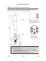
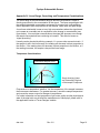
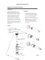
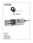
User’s Manual
May 8, 2012
P/N 998-2100
Revision 2.0
TURNER DESIGNS
845 W. Maude Avenue
Sunnyvale, CA 94085
Phone: (408) 749-0994
FAX: (408) 749-0998
Table of Contents
1.
2.
3.
4.
5
Introduction
1.1 Description
4
Inspection and Setup
2.1 Instrument Checklist
2.2 Housing Configurations
2.3 Optional Accessories
2.4 Functional Test
5
5
6
7
Measurements with the Cyclops
3.1 Introduction
3.2 Setting the Gain
3.2.1
Gain Determination Procedure
3.2.2
Static Gain Control
3.2.3
Auto Gaining
3.3 Direct Concentration Calibration
8
8
8
9
9
9
Turbidity Cyclops
4.1 Introduction
4.2 Calibration
11
11
Maintenance and Warranty
5.1
Maintenance
5.1.1 Rinsing
5.1.2 Care for the bulkhead connector
5.1.3 Cleaning the Optics
5.2
Warranty Terms
5.3
Warranty Service
5.4
Out of Warranty Service
12
12
12
12
12
13
13
Appendices
A
Specifications
B
Recommended Measurement Practices
C
Wiring Guide
D
Cable Guide
E
Pigtail Cable and Connector Information
F
Controlling the Gain
G
Linear Range, Quenching and Temperature Considerations
H
Installing the Shade Cap
I
Installing the Flow Cap
J
Installing and Using the Solid Secondary Standard
K
Using the Cyclops Submersible Sensor with the DataBank
L
Optical Specification Guide
15
16
17
18
19
20
21
22
26
30
36
37
WASTE ELECTRICAL AND ELECTRONIC EQUIPMENT (WEEE) DIRECTIVE
Turner Designs is in the business of designing and selling products that benefit the
well-being of our environment. Accordingly, we are concerned with preserving the
surroundings wherever our instruments are used and happy to work with customers by
complying with the WEEE Directive to reduce the environmental impact resulting from
the use of our products.
WEEE Return Process:
To arrange the return of an end-of-life product, proceed as follows:
If you purchased your instrument through a Turner Designs Distributor please
contact your local representative. They will instruct you where to return the end-oflife product.
If you purchased your instrument directly from Turner Designs please contact
Turner Designs Customer Service
By Phone: 1-408-212-4041 or Toll Free: (877) 316.8049
By Email: Customer Service at [email protected]
Turner Designs will provide a WEEE RMA Number, a Shipping Account Number,
and a Ship to Address. Package and ship the product back to Turner Designs.
The product will be dealt with per Turner Designs’ end-of-life recycling program in an
environmentally friendly way.
Cyclops Submersible Sensor
1. Introduction
1.1 Description
The Turner Designs’ Cyclops Submersible Sensor is an accurate single-channel
detector that can be used for many different applications. It is designed for
integration into multi-parameter systems from which it receives power and
delivers a voltage output proportional to the concentration of the fluorophore,
particle, or compound of interest.
The Cyclops voltage output can be correlated to concentration values by
calibrating with a standard of known concentration.
998-2100
Rev. 2.0
Page 4
Cyclops Submersible Sensor
2. Inspection and Setup
2.1 Instrument Checklist
The Cyclops Submersible Sensor shipment package consists of:
•
Cyclops Submersible Sensor:
Configured and factory scaled for the specified analysis (see Identification
Letter stamped on the connector for specified analysis):
− “C” = Chlorophyll
− “R” = Rhodamine
− “F” = Fluorescein
− “P” = Phycocyanin
− “E” = Phycoerythrin
− “U” = CDOM / fDOM
− “O” = Crude Oil
− “B” = Optical Brighteners
− “T” = Turbidity
“A” = PTSA
− “G” = Refined Fuels
− “A” = PTSA
•
Cyclops Documentation Kit includes:
−
−
−
−
•
User’s Manual
Quick Start Guide
in vivo Calibration Procedure
Cable Guide
Calibration Certificate
2.2 Housing Configurations:
•
Stainless Steel Cyclops-7 (P/N: 2100-000-“Identification Letter”)
•
Plastic or Titanium housings (recommended for highly corrosive
environments or long term deployments).
Titanium Cyclops-7 (P/N: 2100-000-“Identification Letter”T)
Plastic Cyclops-7 (P/N: 2108-000-“Identification Letter”)
Plastic Cyclops-7 with Titanium connector (P/N: 2108-000-“Identification
Letter”T)
•
6000 meter Cyclops-6K (P/N: 2160-000-“Identification Letter”)
998-2100
Rev. 2.0
Page 5
Cyclops Submersible Sensor
2.3 Optional Accessories include:
•
Cyclops Pigtail Cables with Locking Sleeve (see Appendix D for more
information)
− 2 foot Pigtail Cable with Locking Sleeve (P/N 2100-750)
− 5 meter Pigtail Cable with Locking Sleeve (P/N 2100-755)
− 10 meter Pigtail Cable with Locking Sleeve (P/N 2100-751)
− 25 meter Pigtail Cable with Locking Sleeve (P/N 2100-752)
− 50 meter Pigtail Cable with Locking Sleeve (P/N 2100-753)
•
DataBank Handheld Data Logger (see Appendix K) (P/N 2900-000)
•
Flow Cap (see Appendix I for more information)
− Cyclops-7 Stainless Steel and Titanium (P/N 2100-600)
− Cyclops-7 Plastic (P/N 2100-608)
− Cyclops-6K (P/N 2160-600)
•
Shade Cap (see Appendix H for more information)
− Cyclops-7 Stainless Steel and Titanium (P/N 2100-701)
− Cyclops-7 Plastic (P/N 2100-708)
− Cyclops-6K (P/N 2160-700)
•
Solid Secondary Standard (SSS) for in vivo Chlorophyll, Phycocyanin,
Phycoerythrin, Rhodamine, Fluorescein (see Appendix J for more
information)
− Cyclops-7 Stainless Steel and Titanium (P/N 2100-900)
− Cyclops-7 Plastic (P/N 2100-908)
− Cyclops-6K (P/N 2160-900)
•
Solid Secondary Standard (SSS) for UV Sensors (CDOM / fDOM, Optical
Brighteners, Refined Fuels and Crude Oil) (see Appendix J for more
information)
− Cyclops-7 Stainless Steel and Titanium (P/N 2100-904)
− Cyclops-7 Plastic (P/N 2100-905)
− Cyclops-6K (P/N 2160-901)
Solid Secondary Standard
Shade Cap
Flow Cap
998-2100
Rev. 2.0
Page 6
Cyclops Submersible Sensor
2.4 Functional Test
To perform a functional check on the Cyclops, connect the interface colored
wires to the power supply and multi-meter as shown in Figure 1 below.
Additional Equipment required for functional tests:
DC Power Supply, 3 - 15 VDC, >100 mA
Multi-meter to read 0 – 5 VDC
Note: Supply voltages greater than 15 VDC will result in damage to
the sensor.
DC Power Supply
12.00
.015
+
PSU Positive Connection
(Red)
LED
Light
Output
Multimeter
-
3.52
Supply Ground
0 VDC (Black)
10 VDC
Signal Output
“+” (White)
-
+
Blue
(Tie to Green for 10X)
Figure 1.
Brown
(Tie to Green for 100X)
Analog Ground
“-” (Green)
X1(Low) Gain
Leave both wires disconnected
for Functional Check
With the Cyclops connected as shown in Figure 1 answer questions 1-3 by
making the following functional tests:
1. Is the LED on?
Hold a piece of white paper about ½ an inch in-front of the optical head to
ensure the LED is on. Note: Cannot perform this test for Turbidity
sensors because they use IR which is not visible.
2. Is there voltage output?
The multi-meter should be reading some voltage >0 VDC
3. Does the voltage output change?
Move the light source closer to your hand or a surface and check if the
voltage output increases
998-2100
Rev. 2.0
Page 7
Cyclops Submersible Sensor
3. Measurements with the Cyclops
3.1 Introduction
The following information will describe how to:
o
o
o
o
Determine and set the appropriate gain
Calibrate the Cyclops using standards with known concentrations
Make measurements with the Cyclops
Use the Solid Secondary Standard
Note: To make accurate and repeatable measurements it is important to
keep the sensor clean; see section 5.1 for information on cleaning your
sensor.
3.2 Setting the Gain
Gain setting refers to the sensitivity configuration of the sensor. There are three
gain settings; X1, X10 and X100. As the gain increases, the sensitivity
increases and the concentration range decreases.
3.2.1
Gain Determination Procedure
1) For in vivo applications, take a natural sample of water from a
sampling station where you plan to deploy the Cyclops. Applying
good measurement practices, store it properly and quickly transport it
to a laboratory where you have the Cyclops connected to a multi
meter and DC power source (see Figure 1).
2) Pour the water sample into a clean glass beaker and submerge the
optical end of the Cyclops (see Appendix B for “Recommended
Measurement Practices for using your Cyclops in the Lab” for how
best to accomplish these steps).
3) Activate the X10 gain setting (see Wiring Guide Appendix C) if you
believe the sample to represent a typical condition. You would like to
obtain a signal from the sample that is significantly higher than a
blank sample (de-ionized water or filtered seawater), but not a signal
that is close to the maximum of 5 Volts.
4) If the sample signal is high, (>3.0 V for example) you may choose to
use the X1 gain instead of the X10 gain setting so that you avoid
going over scale once you deploy the Cyclops.
5) If the sample signal is very low (<0.3V) you may choose to use the
X100 gain setting to achieve higher sensitivity but a smaller
measurable range
This process is easier for dye tracing applications. Simply create the dye
dilution of interest and record what signal level it provides on the three
gain settings.
998-2100
Rev. 2.0
Page 8
Cyclops Submersible Sensor
3.2.2
Static Gain Control
If integrating into a multi parameter system or data logger that is set up
for “Static Gain Control”, which refers to the use of only one gain setting
at a time, then you must determine which gain to use prior to deployment
(see section 3.2.1) and have an integration cable made to activate that
specific gain (see Appendix C). For most applications the X10 gain will
provide the best sensitivity, range, and resolution.
Customers wanting to dynamically change the gain ranges to achieve
the optimum operating range should refer to “Method 2 – Dynamic Gain
Control” in Appendix F on how to interface with a Data Collection System
with programmable outputs.
3.2.3
Auto Gaining
Certain data loggers or multi parameter systems will have an auto
gaining feature which will automatically adjust the sensitivity according to
the voltage output from the Cyclops sensor. This feature maximizes the
performance of Cyclops sensors allowing users to detect a broad range
of concentrations, obtain the best resolution, and read minimum
detection limits without having to rewire or manually change the sensor’s
sensitivity. Turner Designs manufactures the DataBank Handheld Data
Logger (see Appendix K) which has the auto gain feature and other
functions that maximize the performance of Cyclops sensors.
3.3 Direct Concentration Calibration
Calibrating the Cyclops is a simple process requiring the use of calibration
standards. The Cyclops can be calibrated using a single calibration standard
which correlates the standard’s concentration to the voltage measured for that
specific standard:
1) Connect the Cyclops to a power source and set the Cyclops to a gain setting
(see section 3.2.1 for explanation on how to determine gain)
2) Measure the voltage from a blank sample for the configured gain setting.
Note: A good blank to use for this application is ultra pure or
deionized water.
3) Use a standard of known concentration and create a correlation between the
standard’s concentration and its voltage output
998-2100
Rev. 2.0
Page 9
Cyclops Submersible Sensor
4) Once a correlation has been made, use the following equation to calculate
concentration values for sample measurements for the calibrated gain:
CSample = [(CStd)/(VoltsStd - VoltsBlank)] * (VoltsSample – VoltsBlank)
CStd = Concentration value of standard used for calibration
Csample = Concentration of sample
VoltsStd = Voltage reading from standard concentration
VoltsSample= Voltage reading from sample(s)
VoltsBlank = Voltage reading from blank
998-2100
Rev. 2.0
Page 10
Cyclops Submersible Sensor
4. Turbidity Cyclops
4.1 Introduction
The Turbidity Cyclops measures turbidity using an 850nm light source and
detection of scattered light at a 90-degree angle which is similar to many
modern day bench top turbidity meters. This unit provides a quick and accurate
way to determine in situ turbidity, eliminating the collection and storage of
samples and minimizing the potential error associated with sample handling and
processing.
4.2 Calibration
Calibrating the Turbidity Cyclops is a simple process requiring the use of
calibration standards. Turner Designs recommends purchasing Amco Clear
Analytical Turbidity Standards for non-ratio instruments because these
standards are non-toxic safe solutions consisting mainly of deionized water that
comes prepared in a broad range of concentrations and has a shelf life
guaranteed for one year. The Turbidity Cyclops can be calibrated using a single
calibration standard which correlates the concentration to the voltage measured
for that specific standard:
1) Connect the Turbidity Cyclops to a power source and set the Turbidity
Cyclops to a gain setting (see “Setting the Gain” section 3.2 for explanation
on how to set the gain)
2) Measure the voltage from a blank sample for the configured gain setting.
Note: A good blank to use for this application is ultra pure or
deionized water.
3) Use a turbidity standard of known concentration (NTU) and create a
correlation between the standard (NTU) and its voltage output
4) Once a correlation has been made, use the following equation to calculate
turbidity values for sample measurements for the calibrated gain:
NTUSample = [(NTUStd)/(VoltsStd - VoltsBlank)] * (VoltsSample - VoltsBlank)
NTUStd = Concentration value of standard used for calibration
NTUSample = Concentration of sample
VoltsStd = Voltage reading from standard concentration
VoltsSample= Voltage reading from sample(s)
VoltsBlank = Voltage reading from blank
998-2100
Rev. 2.0
Page 11
Cyclops Submersible Sensor
5. Maintenance and Warranty
5.1 Maintenance
5.1.1
Rinsing
The Cyclops should be rinsed or soaked in fresh water following each
deployment, ideally until it is completely clean again.
5.1.2
Care for the bulkhead connector
A light coat of Silicone spray should be used on the rubber of the male
pins of the bulkhead to aid in sealing. The manufacturer recommends
3M™ Silicone Lubricant Spray or Loctite 8021 spray. Note: You
should avoid using silicone grease. Do NOT use WD-40, it will
destroy the connectors.
5.1.3
Care for the optics
The optical window should be visually inspected after each deployment
following a soaking in fresh water. If cleaning is needed, use optical
tissue to clean the window with soapy water.
Note: The Cyclops should NOT come in contact with any organic
solvents (i.e. acetone, methanol) or strong acids and bases.
The UV Cyclops models are the ONLY Cyclops sensors that can be
calibrated with Quinine Sulfate standards made in Hydrosulfuric Acid. All
other Cyclops models CANNOT be used in Hydrosulfuric Acid.
5.2 Warranty Terms
Turner Designs warrants the Cyclops and accessories to be free from defects in
materials and workmanship under normal use and service for a period of 12
months from the date of shipment from Turner Designs with the following
restrictions:
•
Turner Designs is not responsible for replacing parts damaged by
accident or neglect. Your instrument must be installed according to
instructions in the User’s Manual. Damage from corrosion is not
covered. Damage caused by customer modification of the instrument is
not covered.
•
This warranty covers only Turner Designs products and is not extended
to equipment used with our products. We are not responsible for
accidental or consequential damages, except in those states where this
limitation is not allowed. This warranty gives you specific legal rights and
you may have other rights which vary from state to state.
•
Damage incurred in shipping is not covered.
998-2100
Rev. 2.0
Page 12
Cyclops Submersible Sensor
5.3 Warranty Service
To obtain service during the warranty period, the owner shall take the following
steps:
1. Write, email or call Turner Designs Technical Support and describe as
precisely as possible the nature of the problem.
Phone: 1 (877) 316-8049
Email: [email protected]
2. Carry out any adjustments or tests as suggested by Technical Support.
3. If proper performance is not obtained you will be issued a Return Materials
Authorization number (RMA) to reference. Package the unit, write the RMA
number on the outside of the shipping carton, and ship the instrument,
prepaid, to Turner Designs. If the failure is covered under the warranty
terms the instrument will be repaired and returned free of charge, for all
customers in the contiguous continental United States.
For customers outside of the contiguous continental United States who
purchased equipment from one of our authorized distributors, contact the
distributor. If you purchased directly, contact us. We will repair the
instrument at no charge. Customer pays for shipping, duties, and
documentation to Turner Designs. Turner Designs pays for return shipment
(custom duties, taxes and fees are the responsibility of the customer).
5.4 Out-of-Warranty Service
Follow steps for Warranty Service as listed above. If Technical Support can
assist you by phone or correspondence, we will be glad to, at no charge. Repair
service will be billed on a fixed price basis, plus any applicable duties and/or
taxes. Shipment to Turner Designs should be prepaid. Your bill will include
return shipment freight charges.
Address for Shipment:
Turner Designs, Inc.
845 W. Maude Ave.
Sunnyvale, CA 94085
998-2100
Rev. 2.0
Page 13
Cyclops Submersible Sensor
998-2100
Rev. 2.0
Page 14
Cyclops Submersible Sensor
Appendix A: Specifications
Parameter
Specification
Linearity (full range)
Power Draw
Input Voltage
Signal Output
Temperature Range
Light Source
Excitation Wavelength
Detector
Detection Wavelength
Warm up time
0.99 R2
@ 3V: Max 360 mW
≥ 5V: Max 265 mW
3 – 15 VDC
0 – 5 VDC Analog
Ambient: 0 to 50 °C
Water Temp: -2 to +50 °C
Light Emitting Diode
Visible – Chl, RWT, PC, PE, F
UV
– CDOM / fDOM, Oil, OB, RF, PTSA
IR
– Turbidity
Photodiode
300 – 1100 nm
5 seconds
Dimensions - Cyclops-6K
(Standard) 316 Stainless Steel
(Optional) Titanium
(Optional) Plastic
Titanium
Stainless Steel and Titanium
L: 4.3 in., 10.9 cm; D: 0.875 in., 2.22 cm
Plastic
L: 4.3 in., 10.9 cm; D: 1.25 in., 3.175 cm
L: 6.6 in, 6.76 cm; D: 1.75 in, 4.45 cm
Depth Rating - Cyclops-7
600 meters
Depth Rating - Cyclops-6K
6000 meters
Weight - Cyclops-7
5 oz; 160 gm
Weight - Cyclops-6K
22 oz; 620 gm
Housing Material - Cyclops-7
Housing Material - Cyclops-6K
Dimensions - Cyclops-7
998-2100
Rev. 2.0
Page 15
Cyclops Submersible Sensor
Appendix B: Recommended Measurement Practices
Recommended Lab Practices for Measurements
The following steps will improve the accuracy and repeatability of your
measurements, especially at low concentration levels:
1. Use a non-fluorescent container for your water samples. Note: Plastic may
fluoresce and interfere with the sample’s fluorescence.
2. If using a glass container, place the container on a non-reflective black surface.
3. Ensure that the sensor is more than 3 inches above the bottom of the container.
4. Ensure that the sensor is in the center of the container and has more than 2
inches clearance between the cirumference of the sensor and the inside surface
of the beaker.
Calibrated
Sensor
>2 inches all
round
Glass Beaker
>3
inches
No Air Bubbles
On Optical
Surface
998-2100
Dark/Black
Non-Reflective
Surface
Rev. 2.0
Page 16
Cyclops Submersible Sensor
Appendix C: Wiring Guide
Cyclops-7
Wire
Pin Number
Function
Connection
Red
1
Supply Voltage
3 – 15 VDC
PSU – Positive Connection
Black
2
Supply Ground, 0VDC
PSU – Ground Connection
White
3
Green
4
Blue
5
Brown
6
Signal Out to data logger
“+”
0 – 5VDC
Analog Ground “-”,
0 VDC
X10 Gain, (Medium
Sensitivity)
X100 Gain, (High
Sensitivity)
Multimeter Positive
Connection
Multimeter Negative
Connection
See table below
See table below
Gain Switching Table
Gain
Chl Range
(µg/L)
RWT
Range
(ppb)
TRB
Range
(NTU)
Not connected
X1
0 - 500
0 – 1,000
0-3000
Connected to
analog ground
Not connected
X 10
0 – 50
0 - 100
0-1000
Not connected
Connected to
analog ground
X 100
0–5
0 - 10
0-100
Gain 10
(Blue)
Gain 100
(Brown)
Not connected
998-2100
Rev. 2.0
Page 17
Cyclops Submersible Sensor
Appendix D: Cable Guide
Cyclops Pigtail Cable with Locking Sleeve
♦
2 foot Pigtail Cable with Locking Sleeve (P/N 2100-750) shown
♦
5 Meter Pigtail Cable with Locking Sleeve (P/N 2100-755)
♦
10 Meter Pigtail Cable with Locking Sleeve (P/N 2100-751)
♦
25 Meter Pigtail Cable with Locking Sleeve (P/N 2100-752)
♦
50 Meter Pigtail Cable with Locking Sleeve (P/N 2100-753)
Any of the cables listed above may be used to operate the Cyclops.
2
6
1
5
3
4
Color
Pin
Function
Connection
Supply Voltage
Red
1
Black
2
White
3
Green
4
Blue
5
x10 Gain, Medium Sensitivity
Analog Ground - Blue tied to Green
Brown
6
x100 Gain, High Sensitivity
Analog Ground - Brown tied to Green
998-2100
PSU – Positive Connection
3-15 VDC
Supply Ground
PSU – Ground Connection
0 VDC
Signal Out to data logger, “+”,
0-5 VDC
Analog Ground,
Positive Connection
Negative Connection – Analog Ground
“-”, 0 VDC
Rev. 2.0
Page 18
Cyclops Submersible Sensor
Appendix E: Pigtail Cable and Connector Information
Dimension details of 24” length cable with 20 gauge colored lead wire, connects to 6 pin
male connector. (Cable manufacturer/Part No: IMPULSE/MCIL-6-FS)
Female locking sleeve,
(Impulse P/No. MCDLS-F)
2
6
1
5
3
4
In-line connector
contact configuration
(connects to Cyclops).
A maximum cable length up to 300 meters can be connected to the Cyclops if the
following conditions are met:
1)
The cable is shielded and contains 20 gauge conductor size or greater
(i.e. Beldon No. 8426 cable).
2)
The 0-5 volt Analog output is connected to a device (i.e. Data Logger) with
an input impedance of 1 MegOhm or greater.
3)
The supply Voltage to the Cyclops is between 5 and 15 volts.
998-2100
Rev. 2.0
Page 19
Cyclops Submersible Sensor
Appendix F: Controlling the Gain
The operating range can either be set to one of the 3 available ranges, which will be
referred to as "Static Gain Control", or it can be dynamically changed to achieve the
optimum operating range, referred to below as "Dynamic Gain Control". The first
approach is applicable when using the Cyclops as a stand-alone sensor. The
second approach is applicable when the Cyclops is integrated into a system with
control capability.
Both methods are implemented by grounding “driving Low” the appropriate gain
control pin. The X10 and X100 gain control pins are normally in a "High" state if
they are not connected to anything. This means the Cyclops default is the X1 gain
(largest concentration range) mode. The Cyclops can be put into higher gain, lower
concentration range modes, by connecting either the X10 or X100 pin (but not both
at the same time) to ground.
Method 1 - Static Gain Control
Connect the X10 or X100 pin to the analog ground pin of the Cyclops pigtail
connector. See the Gain Switching Table in Appendix C to determine the required
configuration for desired gain/measurement range. See Appendix E for Pigtail
Cable and Connector information. Also, see “Setting the Gain” section 3.2 for more
information on “Static Gain Control”.
Method 2 - Dynamic Gain Control
If you have a Data Collection System (DCS) that has programmable outputs you
can use them to control the Cyclops gain settings. Following are three common
output types found in DCSs and how to connect them to the Cyclops. Refer to your
DCS manual to determine which is appropriate. (For those who want technical data:
the Cyclops’s X10 and X100 gain control pins are connected internally to the input
of a Schmitt trigger inverter, part number 74LVC1G14, and a 100K ohm pull-up
resistor. Both use a 5-Volt power supply.)
Output type 1: Digital Signals
Logic signals can be used to drive the gain control pins. In most cases you can
connect the digital signal output of the DCS directly to the Cyclops gain control pins.
To drive them high, the voltage should be 3 VDC min – 5 VDC max. To drive them
low, the voltage should be 1 VDC max – 0 VDC min. You may need to connect the
Cyclops analog ground to the DCS ground.
Output type 2: Open Collector Signals
This type of output is either open or connected to ground. Connect the Cyclops gain
control pins directly to these outputs. You may need to connect the Cyclops analog
ground to the DCS ground.
Output type 3: Relays
Relays act as a controllable switch. Connect one end of the relay to the Cyclops
analog ground. Connect the other end of the relay to the Cyclops gain control pin.
998-2100
Rev. 2.0
Page 20
Cyclops Submersible Sensor
Appendix G: Linear Range, Quenching and Temperature Considerations
The linear range is the concentration range in which the fluorometer’s output is
directly proportional to the concentration of the signal. The linear range begins with
the smallest detectable concentration and spans to an upper limit (concentration)
that is dependent upon the properties of the material, filters used, and path length.
A non-linear relationship is seen at very high concentrations where the signal does
not increase at a constant rate in comparison to the change in concentration (see
figure below). At even higher concentrations, the signal will decrease even though
the sample concentrations are continuing to increase. This effect is known as
“signal quenching”.
Linearity can be checked by diluting a sample 1:1 or some other convenient ratio. If
the sample is still in the linear range, the reading will decrease in direct proportion to
the dilution. If the reading does not decrease in direct proportion to the dilution, or if
the reading increases, the sample is beyond the linear range.
Temperature Considerations
Fluorometer
Reading
Fluorometer Response Curve
Sample
Quenching Region
Sample
Linear Region
Sample Concentration
Graph showing Linear
and Quenching Regions
of the sample’s response
Fluorescence is temperature sensitive. As the temperature of the sample increases,
the fluorescence decreases. For greatest accuracy, record the sample temperature
and correct the sensor output for changes in temperature.
For further information on how temperature, light, water quality and the physiological
state of the algal cells can all affect the measurement of chlorophyll, please refer to
the application section of Turner Designs’ website.
998-2100
Rev. 2.0
Page 21
Cyclops Submersible Sensor
Appendix H: Installing the Shade Cap
Introduction
Installation
The Shade Cap (P/N: 2100-701) for the
Stainless or Titanium Cyclops-7 Sensor
1. Install the Spacer o-ring approximately 1
offers protection for the optics located at the
½“ from the optical end of the Cyclops-7.
optical end of the instrument. It prevents
The o-ring is intended to fit very tightly on
damage from deploying, recovering, or
the Cyclops-7 and can be difficult to
transporting the instrument in fast-flowing
install. You can use the Tightening Cap to
environments, and/or from bottoming out in
help slide the o-ring on. Soapy water can
shallow environments. The Shade Cap also
be used to lubricate the o-ring, but it
helps block other possible sources of light that
should be rinsed off and dried once the o-
may interfere with the Cyclops-7 Sensor’s
ring is in place.
measurements.
Features
•
Corrosion-resistant material
•
Reduces interference from ambient light
sources.
•
Large flow slots for improved flow
•
Protects optics
Tightening Cap
Stainless or Titanium
Cyclops-7 Sensor
Spacer o-ring
1 ½“
Air purge slots
Flow slots
End Cap
998-2100
Rev. 2.0
Page 22
Cyclops Submersible Sensor
2. Slide the Tightening Cap on from the plug
end of the Cyclops-7 and the Shade Cap
from the optical end of the Cyclops-7 as
shown below, positioning the threads over
the o-ring. Turning clockwise, hand
tighten the Tightening cap onto the Shade
Cap. The Shade Cap is installed correctly
if the optic end of the Cyclops-7 is flush
with the interior base of the Shade Cap.
3. (Optional) Turning clockwise, hand tighten
the End Cap to the other end of the Shade
Cap until it is fully secured to the Shade
Cap. The End Cap prevents sediment
and other debris from entering the shade
cap.
Shade Cap Specifications
Material
Delrin and PVC
Weight
110 g (0.24 lbs.)
Length
12.7 cm (5.0 in.)
Diameter
4.3 cm (1.7 in.)
Depth Rating
600 meters
998-2100
Rev. 2.0
Page 23
Cyclops Submersible Sensor
Installation
Introduction
1. Turning clockwise, hand tighten the air
The Shade Cap (P/N: 2100-708) for the
purge slot end of the Shade Cap onto the
Plastic Cyclops-7 Sensor offers protection for
Plastic Cyclops-7 Sensor’s optical head
the optics located at the optical end of the
until the Shade Cap is fully secured to the
instrument. It prevents damage from
unit.
deploying, recovering, or transporting the
instrument, in fast-flowing environments,
and/or from bottoming out in shallow
environments. The Shade Cap also helps
block other possible sources of light that may
interfere with the Plastic Cyclops-7 Sensor’s
measurements.
Features
2. Turning clockwise, hand tighten the End
•
Threaded ends for easy installation and
removal
•
Corrosion-resistant material
•
In-line design maintains sensor’s diameter
•
Large flow slots for improved flow
Cap to the other end of the Shade Cap
until it is fully secured to the Shade Cap
(Optional).
Completed
Shade Cap
Installation
Plastic Cyclops-7
Sensor
Flow Slots
End Cap
Air Purge Slots
Specifications
998-2100
Rev. 2.0
Material
Delrin
Weight
22.9 g (0.05 lbs.)
Length
9.2 cm (3.62 in.)
Diameter
3.1 cm (1.22 in.)
Depth Rating
600 meters
Page 24
Cyclops Submersible Sensor
Introduction
Installation
The Cyclops-6K Shade Cap (P/N: 2160-700)
1. Turning clockwise, hand tighten the air
offers protection for the optics located at the
purge slot end of the Shade Cap onto the
optical end of the instrument. It prevents
Cyclops-6K Sensor’s optical head until the
damage from deploying, recovering, or
Shade Cap is fully secured to the unit.
transporting the instrument in fast-flowing
environments, and/or from bottoming out in
shallow environments. The Shade Cap also
helps block other possible sources of light that
may interfere with the Cyclops-6K Sensor’s
measurements.
Features
2. Turning clockwise, hand tighten the
Threaded ends for easy installation and
removal
End Cap to the other end of the Shade
•
Corrosion-resistant material
Shade Cap (Optional).
•
In-line design maintains sensor’s diameter
•
Large flow slots
•
Cap until it is fully secured to the
Completed
Shade Cap
Installation
Cyclops-6K
Flow Slots
End Cap
Air Purge Slots
Specifications
998-2100
Rev. 2.0
Material
Delrin
Weight
50.0 g (0.11 lbs.)
Length
9.8 cm (3.86 in.)
Diameter
4.4 cm (1.74 in.)
Depth Rating
6000 meters
Page 25
Cyclops Submersible Sensor
Appendix I: Installing the Flowthrough Cap
Introduction
3.
The Stainless or Titanium Cyclops-7
Flowthrough Cap (P/N 2100-600) was
designed for use with in situ instrument
packages that utilize a submersible pump for
flow through sampling. The Flowthrough Cap
should not be subjected to a pressurized water
source that will exceed 50 PSI of differential
pressure. When using the Flowthrough Cap,
best results will be obtained using the X1 or
X10 Gain Ranges of the Cyclops-7 sensor
Position the compression gasket
approx. 2 inches from the optical end of
the sensor
4.
It is important to check that the O-Ring
installed in the Flowthrough Body
Assembly is squarely seated on the
bottom of the cap. (It acts as a washer
between the sensor and the cap). It is
possible to damage the optical face of
Cyclops-7 if this O-Ring is not in place.
5.
Insert the optical end of Cyclops-7 in the
Flowthrough Body Assembly. With the
Cyclops-7 fully inserted into the cap, slide
the compression gasket towards the
optical end until it bottoms out inside the
cap.
6.
Place threaded end cap over the Cyclops7 sensor, and screw down tightly by hand,
(do not use tools to tighten).
The Cyclops-7 Flowthrough Cap consists of
the following components:
•
1 ea Flowthrough Cap
•
3 ea Compression Gaskets (1 installed, 2
spares)
•
3 ea O-Rings, (1 installed, 2 spares)
Assembly Procedure
1.
Lightly smear soapy water on the inside
of the compression gasket.
2.
Slide the compression gasket over the
optical end of the sensor with the “step”
on the gasket towards the connection
pins end of Cyclops-7.
998-2100
Rev. 2.0
Page 26
Cyclops Submersible Sensor
Summary
The sensor and flowthrough cap are now
ready for use.
Once installed, the Cyclops-7 sensor should
be oriented such that the flow through cap is
facing up. This orientation will prevent bubbles
from collecting on the optics.
Application Note
For Rhodamine WT applications, use highdensity tubing to prevent absorption of the dye
into the tubing. The Cyclops-7 should not
come in contact with any organic solvents (i.e.
acetone, methanol), or strong acids and
bases.
The inlet and outlet ports of the cap accept
3/8” ID tubing. The inlet tubing should be
connected to the side-port on the cap and the
outlet tubing connected to the top-port.
Note: With the Flowthrough Cap installed,
the blank offset for the sensor will be
elevated. If you are interested in
measuring the offset increase, DI water can
be used to measure the blank before and
after the cap installation.
998-2100
Rev. 2.0
Page 27
Cyclops Submersible Sensor
Introduction
Installation Instructions
The Flowthrough Cap (P/N: 2100-608) for the
Plastic Cyclops-7 Sensor was designed to
enable flow through mode. The Flowthrough
Cap will allow the Plastic Cyclops-7 Sensor to
be configured with other instruments used in
flow through systems.
1)
Turning clockwise, fully hand tighten the
Flowthrough Cap housing onto the Plastic
Cyclops-7 Sensor.
2)
Flowthrough Cap installation is complete.
Features
• Facilitates Flow-through sampling
• Eliminates other light sources that may
interfere with sensor measurements
• Protects sensors from damage during
deployment or transport
Out Flow Port
• Helps limit biofouling
• Corrosion-resistant plastic material
NOTE: For optimal
use, Turner Designs
recommends
positioning or
mounting the Plastic
Cyclops-7 Sensor
with Flowthrough
Cap vertically. This
will purge any air
from the system that
might cause skewed
readings.
• Threaded end for easy installation and
removal
Plastic Cyclops-7 Sensor
Ports
In Flow Port
Specifications
Threaded ends
Metal Fastener (See Note Below)
Note: The Metal Fastener secures the ports
to the Flowthrough Cap’s housing. It should
never be removed or tampered with. Doing
so may result in damage to the Flow Cap
ports and cause injury to yourself or others
during operation.
998-2100
Max. Pressure
50 psi
Length (w/ port)
6.4 cm (2.52 in.)
Diameter (w/ port)
6.7 cm (2.64 in.)
Weight
92.2 g (0.203 lbs.)
Max. Volume
5.00 ml
Material
Delrin
Rev. 2.0
Page 28
Cyclops Submersible Sensor
Introduction
Installation
The Flowthrough Cap (P/N: 2160-600) for the
Cyclops-6K is designed to enable flow through
mode. The Flowthrough Cap allows the
Cyclops-6K Sensor to be configured with other
instruments used in flow through systems.
1)
Turning clockwise, fully hand tighten the
Flowthrough Cap housing onto the
Cyclops-6K Sensor.
2)
Flowthrough Cap installation is complete.
Features
•
Facilitates Flow-through sampling
•
Eliminates other light sources that may
interfere with sensor measurements
•
Protects sensors from damage during
deployment or transport
•
Helps limit biofouling
•
Corrosion-resistant plastic material
•
Threaded end for easy installation and
removal
Out Flow Port
NOTE: For optimal
use, Turner Designs
recommends
positioning or
mounting the
Cyclops-6K Sensor
with Flowthrough
Cap vertically. This
will purge any air
from the system that
might cause
skewed readings.
Cyclops-6K Sensor
Ports
In Flow Port
Threaded ends
Metal Fastener (See Note Below)
Note: The Metal Fastener secures the ports
to the Flowthrough Cap’s housing. It
should never be removed or tampered with.
Doing so may result in damage to the Flow
Cap ports and cause injury to yourself or
others during operation.
998-2100
Specifications
Max. Pressure
50 psi
Length (w/ port)
7.1 cm (2.81 in.)
Diameter (w/ port)
7.0 cm (2.77 in.)
Weight
86.2 g (0.19 lbs.)
Max. Volume
5.00 ml
Material
Delrin
Rev. 2.0
Page 29
Cyclops Submersible Sensor
Appendix J: Installing and Using the Solid Secondary Standard
Introduction
The following information describes how to use
the Stainless or Titanium Cyclops-7 Solid
Secondary Standards:
P/N 2100-900
In Vivo Chlorophyll,
Rhodamine WT,
Fluorescein, Phycocyanin,
and Phycoerythrin
P/N 2100-904
CDOM / fDOM, Crude Oil,
Refined Fuels, and Optical
Brighteners
4.
Use a flathead screwdriver to unscrew the
locking nut as far as it will go.
5.
To change the signal level use the green
screwdriver provided and insert the blade
through the hole in the locking nut. Rotate
the screwdriver until it engages with the
adjustment screw that is beneath the
locking nut. Rotate the screw to adjust
the signal level as necessary. Turning
clockwise increases the signal and
counterclockwise decreases the signal.
Features
•
•
•
•
Can be used in place of a primary liquid
standard once a correlation between a
primary standard and the solid standard is
established.
Can be used to check fluorometer stability
and/or check for loss in sensitivity.
Provides a broad range of very stable
fluorescent responses.
Has an adjustment screw allowing users
to set to a desired signal.
Lock nut
Adjustment screw is located
under the locking nut
Insert the supplied green screwdriver through the hole in
the locking nut to reach the adjustment screw.
Installation
1.
Before installing the Solid Secondary
Standard, ensure that the optical surface
of the Cyclops-7 is completely clean and
dry.
6.
Once the desired reading is obtained,
tighten the locking nut so the adjustment
screw is held firmly in place.
2.
Fully mate the Solid Secondary Standard
with the optical end of the Cyclops-7.
7.
3.
Rotate the Solid Secondary Standard in
either direction until you feel the indexing
ball click into the indexed position.
Finish by noting the output voltage and
gain setting used (X1, X10 or X100) in the
“Value” space on the Secondary Standard
label.
8.
Note that the response of every Solid
Secondary Standard is unique. Hence, a
new correlation must be determined for
every sensor. For future identification,
use the “ID” space on the label for a
unique identifier for the Secondary
Standard.
Cyclops-7
Solid Standard
indexing mark
Solid Standard
indexing ball
Align the index mark and indexing ball when mating the
Cyclops-7 and the Solid Secondary Standard.
998-2100
Rev. 2.0
Page 30
Cyclops Submersible Sensor
Specifications
Material
Delrin
Weight
45.0 g (0.099 lbs.)
Length
5.7 cm (2.25 inches)
Base Diameter
3.2 cm (1.25 inches)
A Solid Secondary Standard is not available
for Turbidity Stainless or Titanium Cyclops-7
sensor.
Use of the Solid Secondary
Standard for in vivo Chlorophyll
Applications
1.
Using your Cyclops-7 Fluorometer,
measure a dye solution with known
concentration and record the response as
well as the gain values for that
measurement.
2.
Dry off the optical end of the Cyclops-7,
attach the Solid Secondary Standard to
the fluorometer, and adjust the Solid
Secondary Standard to produce the same
response in the same gain as in step 1.
3.
The Solid Secondary Standard’s signal is
now equivalent to the concentration value
of the dye solution used in step 1and can
be used in place of a liquid primary
standard for future calibration of that
specific Cyclops-7.
Using your Cyclops-7 Fluorometer,
measure a sample containing algae and
record the response and the gain values
for that measurement.
2.
Dry off the optical end of the Cyclops-7,
attach the Solid Secondary Standard to
the fluorometer, and adjust the Solid
Secondary Standard to produce the same
response in the same gain as in step 1.
3.
Perform a chlorophyll extraction to
determine the actual chlorophyll
concentration of the sample.
NOTE: EPA Method 445.0 (in vitro
determination of chlorophyll in
algae) can be found on Turner
Designs’ website.
4.
1.
The Solid Secondary Standard’s signal is
now equivalent to the concentration value
determined from step 3 and can be used
in place of a liquid primary standard for
future calibration of that specific Cyclops-7
Fluorometer.
Note:
Comprehensive information on
dye trace measurements can be
found at the following Turner
Designs website:
http://www.turnerdesigns.com/flu
orescent-dye-tracing
Care and Storage
Solid Secondary Standards should be stored
at room temperature (~20 °C) in their case
when not in use and kept free of dust and
moisture. Special care must be taken with the
UV Solid Secondary Standard P/N 2100-904
to ensure that it is not exposed to UV light for
prolonged periods of time. This can result in
degradation of the standard.
Use of the Solid Secondary
Standard for Dye Tracing
Applications
The Solid Secondary Standard can also be
used to check fluorometer stability when
making dye concentration measurements. If
necessary, the Solid Secondary Standard can
be used to establish a new correlation voltage
without using a calibration solution each time.
998-2100
Rev. 2.0
Page 31
Cyclops Submersible Sensor
Introduction
Installation
The following information describes how to use
the Plastic Cyclops-7 Solid Secondary
Standards:
1)
P/N 2100-908
In Vivo Chlorophyll,
Rhodamine WT,
Fluorescein, Phycocyanin,
and Phycoerythrin
2)
P/N 2100-905
CDOM / fDOM, Crude Oil,
Refined Fuels, and Optical
Brighteners
Align Solid Secondary Standard with
Plastic Cyclops-7 Sensor’s optical head
and snap on the Solid Standard.
Slightly rotate Solid Secondary Standard
until it is set into position. Note: You will
feel/hear a click when the Ball Plunger
seats into position.
Features
•
Can be used in place of a primary liquid
standard once a correlation between a
primary standard and the solid standard is
established.
•
Can be used to check fluorometer stability
and/or check for loss in sensitivity.
•
Provides a broad range of very stable
fluorescent responses.
•
Has an adjustment screw allowing users
to set to a desired signal.
3)
The Solid Secondary Standard’s signal is
now ready to be adjusted using the green
screwdriver provided.
4)
Unscrew the locking nut as far as it will
go.
Insert the green screwdriver through the
hole in the locking nut and rotate until it
engages with the adjustment screw on the
Adjustable Filter beneath the locking nut.
Rotate the Adjustable Filter to adjust the
reading. Turning clockwise increases the
signal and counterclockwise decreases
the signal.
Once the desired reading has been
obtained, the locking nut should be
screwed down to hold the Adjustable Filter
firmly in place.
Ball Plunger
Adjustable
Filter
5)
Solid Secondary
Standard
Locking
Nut
6)
Specifications
7)
Material
Delrin
Weight
65.9 g (0.145 lbs.)
Length
8.2 cm (3.23 inches)
Base Diameter
3.6 cm (1.42 inches)
A Solid Secondary Standard is not available
for Turbidity Plastic Cyclops-7 sensor.
998-2100
Note: The response of every solid
secondary standard is unique. A new
correlation must be determined for
every sensor.
Rev. 2.0
Page 32
Cyclops Submersible Sensor
Use of the Solid Secondary
Standard for in vivo Chlorophyll
Applications
1.
Using your Cyclops-7 Fluorometer,
measure a sample containing algae and
record the response and the gain values
for that measurement.
2.
Dry off the optical end of the Cyclops-7,
attach the Solid Secondary Standard to
the fluorometer, and adjust the Solid
Secondary Standard to produce the same
response in the same gain as in step 1.
3.
Perform a chlorophyll extraction to
determine the actual chlorophyll
concentration of the sample.
Note:
4.
3.
EPA Method 445.0 (in vitro
determination of chlorophyll in
algae) can be found on Turner
Designs’ website.
The Solid Secondary Standard’s signal is
now equivalent to the concentration value
determined from step 3 and can be used
in place of a liquid primary standard for
future calibration of that specific Cyclops-7
Fluorometer.
The Solid Secondary Standard’s signal is
now equivalent to the concentration value
of the dye solution used in step 1and can
be used in place of a liquid primary
standard for future calibration of that
specific Cyclops-7.
Note:
Comprehensive information on
dye trace measurements can be
found at the following Turner
Designs website:
http://www.turnerdesigns.com/flu
orescent-dye-tracing
Care and Storage
Solid Secondary Standards should be stored
at room temperature (~20 °C) in their case
when not in use and kept free of dust and
moisture. Special care must be taken with the
UV Solid Secondary Standard P/N 2100-905
to ensure that it is not exposed to UV light for
prolonged periods of time. This can result in
degradation of the standard.
Use of the Solid Secondary
Standard for Dye Tracing
Applications
The Solid Secondary Standard can also be
used to check fluorometer stability when
making dye concentration measurements. If
necessary, the Solid Secondary Standard can
be used to establish a new correlation voltage
without using a calibration solution each time.
1.
Using your Cyclops-7 Fluorometer,
measure a dye solution with known
concentration and record the response as
well as the gain values for that
measurement.
2.
Dry off the optical end of the Cyclops-7,
attach the Solid Secondary Standard to
the fluorometer, and adjust the Solid
Secondary Standard to produce the same
response in the same gain as in step 1.
998-2100
Rev. 2.0
Page 33
Cyclops Submersible Sensor
Introduction
Installation
The following information describes how to use
the Cyclops-6K Solid Secondary Standards:
1)
P/N 2160-900
P/N 2160-901
In Vivo Chlorophyll,
Phycocyanin, and
Phycoerythrin
2)
CDOM / fDOM and Crude
Oil
Align Solid Secondary Standard with
Cyclops-6K Sensor’s optical head and
snap on the Solid Secondary Standard.
Slightly rotate Solid Secondary Standard
until it is set into position. Note: You will
feel/hear a click when the Ball Plunger
seats into position.
Features
•
Can be used in place of a primary liquid
standard once a correlation between a
primary standard and the solid standard is
established.
•
Can be used to check fluorometer stability
and/or check for loss in sensitivity.
•
Provides a broad range of very stable
fluorescent responses.
•
Has an adjustment screw allowing users
to set to a desired signal.
3)
The Solid Standard’s signal is now ready
to be adjusted using the green
screwdriver provided with the Solid
Standard
4)
Unscrew the locking nut as far as it will
go.
Insert the green screwdriver through the
hole in the locking nut and rotate until it
engages with the adjustment screw on the
Adjustable Filter beneath the locking nut.
Rotate the Adjustable Filter to adjust the
reading. Turning clockwise increases the
signal and counterclockwise decreases
the signal.
Once the desired reading has been
obtained, the locking nut should be
screwed down to hold the Adjustable Filter
firmly in place.
Ball Plunger
Adjustable
Filter
5)
Solid Standard
6)
Locking
Nut
7)
Specifications
Material
Delrin
Weight
90.7 g (0.2 lbs.)
Length
9.7 cm (3.82 inches)
Base Diameter
5.2 cm (2.05 inches)
998-2100
Note: The response of every solid
standard is unique. A new correlation
must be determined for every sensor.
Rev. 2.0
Page 34
Cyclops Submersible Sensor
Use of the Solid Secondary
Standard for in vivo Chlorophyll
Applications
1.
Using your Cyclops-6K Fluorometer,
measure a sample containing algae and
record the response and the gain values
for that measurement.
2.
Dry off the optical end of the Cyclops-6K,
attach the Solid Secondary Standard to
the fluorometer, and adjust the Solid
Secondary Standard to produce the same
response in the same gain as in step 1.
3.
Perform a chlorophyll extraction to
determine the actual chlorophyll
concentration of the sample.
Note:
4.
Care and Storage
Solid Secondary Standards should be stored
at room temperature (~20 degree C) in their
case when not in use and kept free of dust and
moisture. Special care must be taken with the
UV Solid Secondary Standard P/N 2160-901
to ensure that it is not exposed to UV light for
prolonged periods of time. This can result in
degradation of the standard.
EPA Method 445.0 (in vitro
determination of chlorophyll in
algae) can be found on Turner
Designs’ website.
The Solid Secondary Standard’s signal is
now equivalent to the concentration value
determined from step 3 and can be used
in place of a liquid primary standard for
future calibration of that specific Cyclops6K Fluorometer.
998-2100
Rev. 2.0
Page 35
Cyclops Submersible Sensor
Appendix K: Using the Cyclops Submersible Sensor with the DataBank
Cyclops sensors are analog output devices that produce a 0 – 5 volt signal that is
proportional to the fluorophore being measured. Turner Designs offers the
DataBank, a universal handheld meter, datalogger, and power supply
that can be used to maximize performance of Cyclops sensors with
functions such as:
− Auto gaining
− User defined calibrations
− Large internal memory
− Interval logging
The DataBank comes with intuitive GUI software that allows users to
easily calibrate, set up logging, download data, and define parameters
and values necessary to help configure the Cyclops for a specific
application or study. Available options include GPS capability,
external power, travel case, and car charger.
DataBank uses for different sampling protocols:
Multiple Site Measurements – measure fluorescence at different
locations within your water system or across many systems; GPS enabled units
provide latitude/longitude data per location
Profiling – purchase extended cables to allow for vertical profiling
Monitoring – deploy the Cyclops to a fixed location or depth and monitor the signal
over time; set up logging to capture a signal within a specific time frame; download
data while the sensor is deployed and continuously measuring; set up digital data
output via HyperTerminal
For any application or sampling protocol, the DataBank facilitates and maximizes
performance of all Cyclops sensors allowing versatility and flexibility in calibration,
setup, and measurement.
Connecting the Cyclops to Turner Designs’ DataBank:
Simply connect the bare wires from the Cyclops’s pigtail to the DataBank board as
shown below and move the switch to select dV.
Switch should
be set to = dV
Bare wires connected
to DataBank board
Black Blue Brown Red White Green
998-2100
Rev. 2.0
Page 36
Cyclops Submersible Sensor
Appendix L: Optical Specification Guide
P/N
Application
MDL
Dynamic Range
LED
(CWL)
Excitation
Emission
Sol. Std.
XXXX-000-U
CDOM / fDOM
0.15 ppb**
0.5 ppb***
0-1250 ppb**
0-5000 ppb***
365 nm
325/120 nm
470/60 nm
2100-904/905, 2160-901
XXXX-000-C
Chl in vivo
0.025 µg/L
0-500 µg/L
460 nm
465/170 nm
696/44 nm
2100-900/908, 2160-900
XXXX-000-F
Fluorescein Dye
0.01 ppb
0-500 ppb
460 nm
400/150 nm
545/28 nm
2100-900/908
XXXX-000-O
Oil - Crude
0.2 ppb***
0-2700 ppb ***
365 nm
325/120 nm
410-600 nm
2100-904/905, 2160-901
XXXX-000-G
Oil - Fine
2 ppb*
2 ppm****
0-10,000 ppb *
>100 ppm****
285 nm
≤ 290 nm
350/55 nm
2100-904/905
XXXX-000-B
Optical Brighteners for
Wastewater Treatment
0.6 ppb ***
0-15,000 ppb ***
365 nm
325/120 nm
445/15 nm
2100-904/905, 2160-901
XXXX-000-P
Phycocyanin (Freshwater
Cyanobacteria)
2 ppbPC
0-40,000 ppbPC
590 nm
≤ 595 nm
≥ 630 nm
2100-900/908, 2160-900
XXXX-000-E
Phycoerythrin (Marine
Cyanobacteria)
0.15 ppbPE
0-750 ppbPE
525 nm
515-547 nm
≥ 590 nm
2100-900/908, 2160-900
XXXX-000-R
Rhodamine Dye
0.01 ppb
0-1000 ppb
530 nm
535/60 nm
590-715 nm
2100-900/908
XXXX-000-T
Turbidity
0.05 NTU
0-3000 NTU
850 nm
850 nm
850 nm
N/A
XXXX-000-A
PTSA
0.1 ppb***
0-650 ppb***
365 nm
325/120 nm
405/10 nm
2100-904/905
* 1,5-Naphthalene Disulfonic Disodium Salt
** Quinine Sulfate
*** PTSA (1,3,6,8-Pyrenetetrasulfonic Acid Tetrasodium Salt)
**** BTEX (Benzene, Toluene, Ethylbenzene, Xylenes)
PC
Phycocyanin pigment from Prozyme diluted in deionized water http://prozyme.com/
PE
Phycoerythrin pigment from Prozyme diluted in deionized water http://prozyme.com/
998-2100
Rev. 2.0
Page 37