1
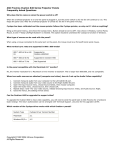
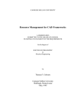
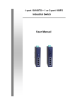
Cyclops
User’s Manual
Revision 3.x.x
June 19, 2013
Contents
Background ................................................................................................................................................... 1
Interface ........................................................................................................................................................ 1
Normal Operation ..................................................................................................................................... 1
Controller Input Type ............................................................................................................................ 1
Communication......................................................................................................................................... 2
Sensitivity ...................................................................................................................................................... 3
Operating Modes .......................................................................................................................................... 3
Normal ...................................................................................................................................................... 4
Self-Test .................................................................................................................................................... 4
Full Debug ................................................................................................................................................. 4
Raw Samples ............................................................................................................................................. 4
Log Arrivals ................................................................................................................................................ 4
Download Log ........................................................................................................................................... 4
Hazardous Locations ..................................................................................................................................... 5
Cyclops IS .................................................................................................................................................. 5
Cyclops ExP................................................................................................................................................ 5
Cathodic Protection ...................................................................................................................................... 5
ii
Background
The Cyclops is a revolutionary new magnetic field sensor that can detect the movement of a ferrous
object. It is sensitive enough to use with non-ferrous objects by detecting the movement of other
ferrous system components. It features a rugged aluminum case with support for a hose clamp, a ½”
NPT strain relief port, and captive screws in the lid. The adjustable sensitivity dial allows the operator to
reduce sensitivity to eliminate false detections in noisy environments or increase sensitivity for hard to
detect and non-ferrous objects.
Cyclops is the only sensor on the market that features a communication mode where you can upgrade
the firmware, access more sensitivity settings, and see real time readings to troubleshoot hard to detect
situations. This microprocessor based design incorporates noise reducing filters and also controls the
output switch to give a clean, 5 second minimum switch closure that is easy for any controller to detect.
Interface
Normal Operation
Each Cyclops sensor is factory programmed to operate as dry contact that closes when an arrival occurs.
The physical wiring and descriptions of the connections are shown below:
COM – The common (COM) is connected to ground. When an arrival occurs, current will flow through
the signal (SIG) connection to ground. There is 100 Ohms of impedance in this path to limit the current.
SIG – Connect this to the input signal on your controller that supports a dry contact. Please see below
for voltage based inputs.
PWR – Provides power for the sensor to operate. It requires a minimum of 4.5 V DC and is rated to
safely take a voltage up to 28 V DC. This power must be available any time the sensor is expected to
detect an arrival as there is no internal battery.
Controller Input Type
The Cyclops has been designed with an open collector field effect transistor (FET) so that it acts as a dry
contact, which ensures that it can be connected directly to most controllers. Most magnetic sensors
available on the market are designed to act as a dry contact, so the Cyclops can easily be used as a
replacement sensor for any system. A dry contact input on a controller features as internal pull up
resistor. When the contact is open, the internal input will read the system voltage. When the contact
closes, the input will now read ground.
1
Cyclops
ETC Controller
PWR
SIG
COM
PWR
SIG
COM
100kΩ
5V
To Input
100Ω
Figure 1 - Typical Dry Contact Interface
When using a programmable logic controller (PLC) or other application specific controller (i.e. Flow
Computer) it is possible that you need to connect to a voltage based input. This type of input is
expecting to see a change in the voltage and is not directly compatible with the Cyclops because it closes
a switch instead of sending back a voltage. The difference is that there is no internal pull up resistor
provided by these controllers, so an external pull up resistor must be connected. Connecting a 100kΩ
resistor between the power and input on the controller will allow these systems to connect to a Cyclops.
When the Cyclops switch is open, the input will see the voltage coming from the power connection.
When the switch closes, the input will be pulled to ground. This difference in voltage can then be
detected.
Controller w/ Voltage Input
Cyclops
PWR
SIG
COM
PWR
SIG
COM
100kΩ
To Input
100Ω
5 - 24 V
Figure 2 - External Resistor for Voltage Input
Communication
The communication interface is basic serial interface which acts as one half of an RS-485 interface. It is
multiplexed with the SIG connection. Since the other half of the RS-485 signal is not present and there is
no internal RS-485 transceiver, this interface may not work with all RS-485 devices. Typically any RS-485
device must have the other half of the signal tied to power through a pull up resistor. ETC does sell
devices and cables that are compatible with this interface.
Figure 3 - Programming Adapter with Cyclops Cable
2
The above is an example of an adapter and a specialized cable that can be used to make this connection.
Please note that this is not considered safe for use when connecting to the Cyclops in a hazardous
location. ETC can provide an alternate solution that is safe to use in a hazardous location.
When the sensitivity dial is set to 0, Cyclops enters a mode where it listens for external commands on
the SIG line. Using ETC Vision, you can program new firmware, change the operating mode, and adjust
the sensitivity.
Sensitivity
The sensitivity dial does not change the signal in any way. It is simply an interface to allow the operator
to adjust the threshold at which the switch will be closed. By default, the switch is set to 4, which is the
middle of the range. The higher the number, the more sensitivity or lower the threshold. When set to
0, the Cyclops enters the communication mode, does not take magnetic readings, and does not operate
the switch.
The magnetic sensor has an incredible amount of sensitivity, more than is needed for sensing any
material type. To prevent false detections the maximum sensitivity has been limited by default. Setting
7 has a default detection threshold of 25 counts, even though it could go as low as 1. Using the
communication mode, the detection threshold for setting 7 can be adjusted to make the sensor more or
less sensitive. Because there is some noise in the readings, the threshold can only be set as low as 10.
The threshold for each sensitivity dial setting is automatically calculated by doubling the threshold from
the next most sensitive setting. The net result is that each dial setting is twice as sensitive as the
previous setting.
The table below highlights the relationship between sensitivity setting and detection threshold:
Setting
7
6
5
4
3
2
1
Threshold
T
Tx2
Tx4
Tx8
T x 16
T x 32
T x 64
Default Value
25
50
100
200
400
800
1600
Operating Modes
There are several operating modes that can be entered while the sensitivity dial is in position 0. The
sensor will not start operating in a given mode until the sensitivity dial is set to a non-zero position.
Before connecting the Cyclops to a controller, the mode must be set to Normal. If the mode is not set to
Normal, the detection algorithm will not run and data that is being sent out the SIG connection will trip
the controller.
3
Normal
This is the mode that each sensor is shipped in. When the sensitivity dial is set to any number other
than 0, the sensor will take magnetic readings, calculate a baseline and compare the current reading to
see if it has surpassed the threshold. When the threshold is exceeded, the switch is closed. The switch
will remain closed for a minimum of 5 seconds. Any time that the threshold is exceeded, the timer is
restarted. This means that as long as movement of a ferrous object continues in front of the sensor, the
switch will remain closed.
Note: Since the baseline average is continually updated, a static object will eventually cause the switch
to open since the reading will no longer exceed the threshold.
Self-Test
This mode will automatically run a current loop under the magnetic sensor, generating a magnetic field.
The test will cycle through a series of different levels of current so that a change can be seen in the
readings. A swing of a least 4000 counts between the minimum and maximum is considered acceptable.
Run a capture in ETC Vision to see the real time readings during the self-test.
Full Debug
This mode will run just like the normal mode, but instead of controlling the switch, the SIG wire is used
to stream live data to ETC Vision. This data includes the current readings, baseline, and current switch
position. Run a capture in ETC Vision to see the real time stream of these values.
Raw Samples
The Raw Samples mode is similar to the Full Debug mode. It will take magnetic readings and stream
data that is captured by ETC Vision. The difference is that no filtering is applied to the readings, no
baseline is calculated, and the switch position is not determined, nor is it transmitted out. This mode
essentially eliminates all internal algorithms to give an accurate picture of the readings coming from the
magnetic sensor.
Log Arrivals
Log Arrivals tells the sensor to operate in normal mode, but to record some debug information when an
arrival is detected. There is a very limited amount of space, so the number of log entries and amount of
information stored per arrival is minimal.
Download Log
This mode will download the information that was captured when in Log Arrivals mode. ETC Vision is
setup to set the sensor into this mode and then capture and record the information as it is transmitted
from Cyclops.
4
Hazardous Locations
There are two models of Cyclops available, each with its own enclosure and corresponding hazardous
locations certification. Both products are internally identical, so they are electrically connected,
adjusted, and programmed in the same manner.
Cyclops IS
The Cyclops IS has been tested and approved as intrinsically safe for use in the most hazardous
locations. When used with an intrinsically safe controller in the same hazardous locations area it can be
connected directly without any other electrical barrier.
The following is the CSA Certification for Canada and the US:
Class I, Division 1, Groups A, B, C and D; Ex ia IIB T4
Class I, Zone 0, AEx ia IIB T4
When connecting to a controller that is rated for a less hazardous area (i.e. a Class I Div 2 PLC/RTU), and
intrinsic safety barrier must be used. This barrier ensures that the higher currents and voltages allowed
in one area are not transmitted to the more hazardous location under failure conditions.
Cyclops ExP
The Cyclops ExP has been tested and approved as explosion proof. If an unsafe voltage or current is
transmitted to the sensor under failure conditions, any resultant explosion will be contained within the
device.
The following is the CSA Certification for Canada and the US:
Class I, Division 1, Groups B, C and D; Ex d IIB T4
Class I, Zone 1, AEx d IIB T4
The benefit of the Cyclops ExP is that it can be connected directly to a controller that is rated for a less
hazardous area (i.e. a Class I Div 2 PLC/RTU). The connector and wiring used must adhere to explosion
proof standards, but the added complexity and expense associated with an intrinsic safety barrier can be
eliminated.
Cathodic Protection
A common problem with magnetic sensors is that they often become an electrical path between the
well and the controller. Often, high voltages associated with cathodic protection can leak back through
the sensor to the controller, causing erratic behavior or permanent damage.
The Cyclops has been designed such that its internal circuitry does not come in contact with the case.
This means that even if the case comes in contact with a surface that has a stray voltage; it will not be
transmitted back through the wiring to the controller.
5
Please do keep in mind that any shielding on the cable that is connected to the case of the Cyclops will
act as a path for any stray voltage to travel.
6