1
Altivar 21
User manual
Retain for future use
LONWORKS ® card
VW3 A21 312
####
####
####
Contents
Important Information _________________________________________________________________________________________ 5
Before you begin_____________________________________________________________________________________________ 6
Introduction _________________________________________________________________________________________________ 7
Documentation structure_______________________________________________________________________________________ 8
Hardware setup _____________________________________________________________________________________________ 9
Receipt _________________________________________________________________________________________________ 9
Hardware description ______________________________________________________________________________________ 9
Use of RS485 communication port ____________________________________________________________________________ 9
Description of terminals ___________________________________________________________________________________ 10
Installing the card in the drive _______________________________________________________________________________ 11
Connecting to the bus________________________________________________________________________________________
Topology _______________________________________________________________________________________________
Cable routing practices ____________________________________________________________________________________
Wiring the LONWORKS® connector ___________________________________________________________________________
12
12
13
13
Configuration ______________________________________________________________________________________________
Drive parameters overriden by the LONWORKS® network__________________________________________________________
Configuration of the internal communication ___________________________________________________________________
Configuration of the control_________________________________________________________________________________
Control by the LONWORKS® network_______________________________________________________________________
Control by terminals, monitoring by the LONWORKS® network ___________________________________________________
Control by the LONWORKS® network, switching setpoint to terminals by logic input___________________________________
Setpoint by the LONWORKS® network, switching commands to terminals by logic input _______________________________
Configuration of the LONWORKS® fault ________________________________________________________________________
14
14
14
15
15
16
17
17
18
Diagnostics ________________________________________________________________________________________________ 20
Service LED ____________________________________________________________________________________________ 20
Troubleshooting _________________________________________________________________________________________ 20
Functional profile ___________________________________________________________________________________________
Objects supported________________________________________________________________________________________
LONMARK Node Object profile_______________________________________________________________________________
LONMARK Variable Speed Motor Drive profile___________________________________________________________________
21
21
21
22
Network variables and configuration properties ____________________________________________________________________
List of network variables and configuration properties ____________________________________________________________
Commands and setpoints __________________________________________________________________________________
Drive Speed Setpoint (nviDrvSpeedStpt) ___________________________________________________________________
Drive Speed Setpoint Scaling (nviDrvSpeedScale) ___________________________________________________________
Default Value for nviDrvSpeedScale (nciDrvSpeedScale) ______________________________________________________
Frequency setpoint (nviInvSetFreq) _______________________________________________________________________
Reset command (nviResetFault) _________________________________________________________________________
Status and output velocity__________________________________________________________________________________
Drive Speed Feedback (nvoDrvSpeed) ____________________________________________________________________
Drive Velocity feedback (nvoDrvFeedback) _________________________________________________________________
Output frequency (nvoInvOutFreq) ________________________________________________________________________
Drive status (nvoStatusWord)____________________________________________________________________________
Alarms_________________________________________________________________________________________________
Alarm code (nvoDrvAlarm) ______________________________________________________________________________
Alarm status (nvoAlarmWord)____________________________________________________________________________
Measurements __________________________________________________________________________________________
Drive Output Current (nvoDrvCurnt) _______________________________________________________________________
Drive Total Running Hours (nvoDrvRunHours) ______________________________________________________________
Energy consumption (nvoDrvEnergy)______________________________________________________________________
Torque actual value (nvoTorque) _________________________________________________________________________
Monitoring of digital inputs _________________________________________________________________________________
Monitoring of digital input F (nvoDigitalIn1) _________________________________________________________________
Monitoring of digital input R (nvoDigitalIn2) _________________________________________________________________
Monitoring of analog inputs_________________________________________________________________________________
Monitoring of analog input VIB (nvoAnalogIn2) ______________________________________________________________
Control of digital outputs ___________________________________________________________________________________
Control of relay FL (nviRelay1) ___________________________________________________________________________
Emergency _____________________________________________________________________________________________
Emergency command (nviEmergOverride) _________________________________________________________________
Emergency status (nvoEmergStatus) ______________________________________________________________________
23
23
25
25
25
25
26
26
28
28
28
28
29
31
31
31
32
32
32
32
32
33
33
33
33
33
33
33
34
34
34
3
Contents
Adjustment _____________________________________________________________________________________________
Maximum Motor Speed (nciMaxSpeed) ____________________________________________________________________
Minimum Motor Speed (nciMinSpeed) _____________________________________________________________________
Nominal Motor Speed in RPM (nciNmlSpeed) _______________________________________________________________
Nominal Motor Frequency (nciNmlFreq)____________________________________________________________________
Minimum Ramp Up Time (nciRampUpTm)__________________________________________________________________
Minimum Ramp Down Time (nciRampDownTm) _____________________________________________________________
Parameter access________________________________________________________________________________________
nviParamCmd, nvoParamResp __________________________________________________________________________
Identification ____________________________________________________________________________________________
Location Label (nciLocation)_____________________________________________________________________________
Identification (nvoTypeVer)______________________________________________________________________________
Network management_____________________________________________________________________________________
Send Heartbeat Time (nciSndHrtBt) _______________________________________________________________________
Receive Heartbeat Time (nciRcvHrtBt)_____________________________________________________________________
Minimum Send Time (nciMinOutTm) ______________________________________________________________________
Power supply start waiting time (nciPwUpOutTm) ____________________________________________________________
While every precaution has been taken in the preparation of this document, Schneider
Electric SA assumes no liability for any omissions or errors it may contain, nor for any
damages resulting from the application or use of the information herein.
The products described in this document may be changed or modified at any time,
either from a technical point of view or in the way they are operated. Their description
can in no way be considered contractual.
4
35
35
35
36
36
37
37
38
38
40
40
40
41
41
41
42
42
1. Important Information
NOTICE
Read these instructions carefully, and look at the equipment to become familiar with the device before trying to install, operate, or maintain
it. The following special messages may appear throughout this documentation or on the equipment to warn of potential hazards or to call
attention to information that clarifies or simplifies a procedure.
The addition of this symbol to a Danger or Warning safety label indicates that an electrical hazard exists, which will result in
personnal if the instruction are not followed.
This is the safety alert symbol. It is used to alert you to potential personal injury hazards. Obey all safety messages that follow
this symbol to avoid possible injury or death.
DANGER
DANGER indicates an imminently hazardous situation, which, if not avoided, will result in death, serious injury, or
equipment damage.
WARNING
Warninig indicates a potentially hazardous situation, which, if not avoided, can result in death, serious injury, or
equipment damage.
CAUTION
CAUTION indicates a potentially hazardous situation, which, if not avoided, can result in injury or equipment
damage.
PLEASE NOTE
Electrical equipment should be serviced only by qualified personnel. No responsibility is assumed by Schneider Electric for any
consequences arising out of the use of this material. This document is not intended as an instruction manual for untrained persons.
© 2005 Schneider Electric. All Rights Reserved.
5
2. Before you begin
Read and understand these instructions before performing any procedure with this drive, in order to completely and correctly
utilize excellent performance of this unit.
Besides this user manual, you will find in the chapter "Documentation structure" which manuals we advice you to read to develop software
communicating with Altivar 21.
If you need support, please contact our sales offices.
After reading this instruction manual, please keep it handy for future reference
Read and understand these instructions before performing any procedure with this drive.
DANGER
HAZARDOUS VOLTAGE
• Read and understand the Installation Manual before installing or operating the Altivar 21 drive. Installation, adjustment, repair, and
maintenance must be performed by qualified personnel.
• The user is responsible for compliance with all international and national electrical standards in force concerning protective grounding
of all equipment.
• Many parts of this variable speed drive, including the printed circuit cards, operate at the line voltage. DO NOT TOUCH.
Use only electrically insulated tools.
• DO NOT touch unshielded components or terminal strip screw connections with voltage present.
• DO NOT short across terminals PA and PC or across the DC bus capacitors.
• Install and close all the covers before applying power or starting and stopping the drive.
• Before servicing the variable speed drive
- Disconnect all power.
- Place a “DO NOT TURN ON” label on the variable speed drive disconnect.
- Lock the disconnect in the open position.
• Disconnect all power including external control power that may be present before servicing the drive. WAIT 15 MINUTES to allow the
DC bus capacitors to discharge. Then follow the DC bus voltage measurement procedure given in the Installation Manual to verify that
the DC voltage is less than 45 VDC. The drive LEDs are not accurate indicators of the absence of DC bus voltage.
Electric shock will result in death or serious injury.
CAUTION
DAMAGED EQUIPMENT
Do not install or operate any drive that appears damaged.
Failure to follow this instruction can result in injury or equipment damage.
6
3. Introduction
Thank you for purchasing the LONWORKS® option card (VW3A21312) for Altivar 21 drive.
By installing this card into the Altivar 21, data communication can be made with a host computer or other device via LONWORKS® network.
The communication card has an open-style 3-pin connector for connection to the network. It supports free topology at 78 kbit/s.
Data exchanges give access to all Altivar 21 functions:
• Control (start, stop, reset, setpoint),
• Monitoring (status, current, voltage, thermal state...),
• Diagnostics (alarms).
The LONWORKS® resource files (.XIF...) that provide the network configuration tools (LonMaker...) with device information are available on
the Web site www.telemecanique.com and on the CDROM delivered with each drive.
The plug-in software tool that provides easy access to setting-up, testing and monitoring the ATV21 drive is also available on the Web site
www.telemecanique.com and on the CDROM delivered with each drive.
LONWORKS®, LONMARK®, LonMaker, Neuron are trademarks of Echelon Corporation registered in the United States and other countries.
LONMARK and LONMARK Logo are managed, granted, and used by LONMARK International under a license granted by Echelon Corporation.
7
4. Documentation structure
b LONWORKS® ATV21 manual
The present LONWORKS® user manual describes:
• connection to LonWorks® network,
• configuration of the communication-specific parameters via the HMI,
• diagnostics,
• networks variables.
You will also find important information in other Altivar 21 technical documents. They are available on the Web site www.telemecanique.com
and on the CDROM delivered with each drive:
b ATV21 user manual
This manual describes:
• How to assemble the drive,
• How to connect the drive,
• The functions and the parameters of the drive,
• How to use the drive HMI.
If you use the Parameter access function of (nviParamCmd, nvoParamResp), will find in this manual the address and possible values of
the parameters of the drive.
b Modbus ATV21 manual
This manual describes:
• Connection to the bus or network,
• Configuration of the communication-specific parameters,
• Diagnostics,
• Software setup,
• Modbus services supported.
If you use the Parameter access function of (nviParamCmd, nvoParamResp), will find in this manual the address and possible values of
additional parameters not described in ATV21 user manual.
8
5. Hardware setup
5. 1. Receipt
• Check that the card reference printed on the label is the same as that on the delivery note corresponding to the purchase order.
• Remove the option card from its packaging and check that it has not been damaged in transit.
• The LONWORKS® card is shipped together with the following accessories. On opening the packing case, check to see if the following
accessories are contained or not.
- 1 cabling label and 2 name plates (1 sheet),
- 1 insulating sheet,
- 3 neuron ID labels (barcode EAN128).
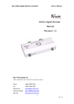
5. 2. Hardware description
Service pin
SW2
Selector switch SW1
- Logic for F, R terminal
(SINK/SOURCE)
- VIB function
(VIB/PTC)
Connector to drive
Service LED
Terminal board
fixing screw hole
(M3 screw)
RS485 communication port
Earth connection terminal
LONWORKS® network detachable terminal
DANGER
• Operate service pin only when a cover for the main circuit terminal is attached. Otherwise, it could lead to electric
shocks.
• Operate service pin using a non-conductive stick. When it is operated with a conductive stick, it could lead to
electric shock
5. 3. Use of RS485 communication port
Serial communication (2-wire RS485) option can be used for Modbus, PC software or remote keypad.
One internal communication line is available either for the RS485 communication port or for the LONWORKS® port.
So, while RS485 communication is used (connected to the appropriate cable or interface) the LONWORKS® port is disabled.
9
5. Hardware setup
5. 4. Description of terminals
Terminal Function
symbol
NETA
®
NETB LONWORKS transmission data / reception data.
Electrical specifications
No polarity.
LONWORKS communication shield terminal.
This terminal is not connected to any
other circuit of the card. Ground this
terminal in a location separated from
the ground of power line.
Grounding terminal
Please connect to network ground.
F
Multifunctional programmable logic input.
It has forward rotation function in default setting.
ON: forward rotation drive
OFF: slowdown and stop
No voltage contact input
24VDC, 5mA or less.
R
Multifunctional programmable contact input.
It has reverse rotation function in default setting.
ON: reverse rotation drive
OFF: slowdown and stop
SHLD
G/E
®
Internal circuits
Spark
gap
SINK
SOURCE
SINK/SOURCE can be selected with
SW1.
VIB
Multifunction programmable analog input.
It has speed set point function in the default setting. (0 to 10VDC
60Hz frequency with 0 to 10VDC input). In addition, this
Internal impedance: 30kohm
terminal can be used as PTC input by setting the
parameters (f645 and f646) and SW1.
CC
Control circuit equipotential terminal
-
P24
24 VDC power supply output
24VDC-50mA
FLA
FLB
FLC
Multifunctional programmable relay contact outputs.
30VDC-0.5A
Default setting is set to detect the activation of the
250VAC-1A
inverter protection function.
(cos ϕ = 1)
Contact across FLA-FLC is closed and FLB-FLC is 250VAC-0.5A
(cos ϕ = 0.4)
opened during protection function operation.
-
DANGER
Do not change switch settings while power is on.
It may damage the product or lead to electric shocks and breakdown.
When setting the VIB function, set the parameter after configuring removed motor cables. The motor may suddenly
start and that could result in injury.
10
5. Hardware setup
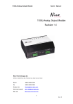
5. 5. Installing the card in the drive
Install the LONWORKS® card in ATV21 as follows.
1 Turn off the input power of ATV21 and wait for at least 10 minutes and then check that the CHARGE lamp on ATV21 is no longer lit.
2 Open the ATV21 front cover, remove the terminal board fixing screw and take off the ATV21 standard terminal board.
(Be careful not to lose the terminal board fixing screw when removed since it may be used again.)
3 Perform wiring an inverter before installing LONWORKS® card.
4 Please attach the insulating sheet in ATV21. (Fix to the terminal board fixing screw hole and ATV21 catch pin.)
5 Install the LONWORKS® card over the insulating sheet and secure it with the board fixing screw (M3 tapping screw tightening torque: 0.7
to 0.8Nm).
6 Stick the cabling label for LONWORKS® card on the standard cabling label stuck on the reverse side of the ATV21 front cover. And stick
the LONWORKS® card nameplate near the standard nameplate. (Be careful not to cover slits on the ATV21 enclosure.
Note: To install or remove the terminal board, make it slide in or out in parallel with board.
Cabling label position
Terminal board M3 fixing screw
(tightening torque 0.7 to 0.8 Nm)
Card fixing screw hole
Example
Stick the VW3 A21312 nameplate
ATV21 nameplate
ATV21 Standard
terminal board
Insulating seat
(attached)
LonWorks card
VW3 A21312
11
6. Connecting to the bus
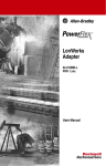
6. 1. Topology
The LONWORKS® card supports free topology wiring and operates as well with bus, loop or star topologies:
Free topology system
Free topology has many advantages:
1 The installer is free to select the method of wiring that best suits the installation, reducing the need for advanced planning and allowing
last minute changes at the installation site.
2 If installers have been trained to use one style of wiring for all installations, free topology technology can be introduced without requiring
retraining.
3 Retrofit installations with existing wiring plants can be accommodated with minimal, if any rewiring.
Typical wiring topologies
Termination
Singly terminated bus topology
Termination
Termination
Termination
Doubly terminated bus topology
Termination
Star topology
Termination
Mixed topology
Loop topology
12
6. Connecting to the bus
6. 2. Cable routing practices
When wiring Altivar 21 drives to a LONWORKS® network, follow all wiring practices required by national and local electrical codes. Also
observe the following guidelines:
• Avoid areas of high temperature, moisture, vibration, or other mechanical stress.
• Secure the cable where necessary to prevent its weight and the weight of other cables from pulling or twisting the cable.
• Use cable ducts, raceways, or other structures to protect the cable. Use these structures for signal wiring paths. They must not contain
power wiring.
• Avoid sources of electrical interference that can induce noise into the cable. Use the maximum practicable separation from such sources.
When planning cable routing within a building, follow these guidelines:
• Maintain a minimum separation of 1 m from the following equipment:
- air conditioners and large blowers,
- elevators and escalators,
- radios and televisions,
- intercom and security systems,
- fluorescent, incandescent, and neon lighting fixtures.
• Maintain a minimum separation of 3 m from the following equipment:
- line and motor power wiring,
- transformers,
- generators,
- alternators.
When wiring in electrical equipment rooms or large electrical equipment line-ups, observe the following guidelines for cable segregation
and separation of circuits:
• Use metallic conduit for drive wiring. Do not run control network and power wiring in the same conduit.
• Separate non-metallic conduits or cable trays used to carry power wiring from metallic conduit carrying low-level control network wiring
by at least 300 mm.
• Separate metallic conduits carrying power wiring or low-level control network wiring by at least 80 mm.
• Cross the metallic conduits and non-metallic conduits at right angles whenever power and control network wiring cross.
• Attenuate conducted emissions from the drive to the line in some installations to prevent interference with telecommunication, radio, and
sensitive electronic equipment. Such instances may require attenuating filters. Consult the Altivar catalog for selection and application of
these filters.
6. 3. Wiring the LONWORKS® connector
The figure and the table below show the pin-outs of the card connectors. The removable LONWORKS® female connector attaches to the
network cable.
A S B
Pin
A
S
B
Name
Net A
Shield
Net B
• Cable sheath should be peeled off by about 10 mm.
• For wiring work, use a fat blade screwdriver with a 0.6 mm thick and 3.5 mm width blade.
• Tightening torque for the terminal block is 0.5 to 0.6 Nm.
13
7. Configuration
7. 1. Drive parameters overriden by the LONWORKS® network
The LONWORKS® card will automatically override edit some of the inverter parameters below so that they should not be edited from the drive
dispay:
Maximum frequency fh
Upper limit frequency ul
Lower limit frequency ll
Acceleration time 1 acc
Deceleration time 1 dec
Base frequency 1 vl
7. 2. Configuration of the internal communication
Set up the inverter parameters as follows. To update, reset the power of inverter. If these parameters are set to incorrect value, the
LONWORKS® card cannot work normally.
Parameter
f800
f801
f803
f829
f851
Function
Communication speed
Parity
Communication error trip time
Communication protocol
Behaviour at communication fault
Description
Set 1 (19200bps), default value.
Set 1 (even), default value.
Set communication time out period.
Set 1 (MODBUS-RTU)
Select the inverter action after communication fault.
Refer to “7. 4.“Configuration of the LONWORKS® fault”, page 18.
WARNING
Set up Communication fault function f803, (see the ATV21 user manual for details) to stop the inverter when this
option card is deactivated by an unusual event such as tripping, an operating error, power outage, failure, etc.
Deactivated option card may cause an accident, if the "Communication fault function" is not properly set up.
14
7. Configuration
7. 3. Configuration of the control
The ATV21 can receive commands and speed setpoint from the LONWORKS® network or from the terminals (F, R, VIB).
In the default configuration both commands and setpoint comes from the LONWORKS® network.
The LOC/REM key of the drive HMI is always available to switch the control to the HMI.
Input R can be configured to switch the control from the LONWORKS® network to the terminals.
Different possibilities are described below.
b Control by the LONWORKS® network
Commands and setpoint come from the LONWORKS® network.
The signals wired on the terminals are ignored.
The LOC/REM key is active.
This is default configuration.
LONWORKS®
commands
Commands
Operation
panel
LONWORKS®
setpoint
Setpoint
Operation
panel
15
7. Configuration
b Control by terminals, monitoring by the LONWORKS® network
Commands and setpoint come from the terminals.
The drive is monitored by the LONWORKS® network.
The LOC/REM key is active.
The function SC/LC or CPCA is assignment of logic input R (F112 = 48).
The logic input R is ON (connected to P24 or CC depending on SINK/SOURCE selection).
Parameter
cmod
fmod
f112
Function
0
2
48
Description
Terminals
VIB
Logic input R configured to "Forced switching from remote to local control" (SC/LC or CPCA)
Logic input R
configured to SC/LC-CPCA
f112 = 48
Network priority switch
Commands CMOD
LONWORKS® commands
Terminals
CATCH
Operation panel
Commands
RELEASE
®
LONWORKS commands
Operation panel
Setpoint FMOD
VIB
LONWORKS® setpoint
Operation panel
LONWORKS® setpoint
CATCH
RELEASE
Operation panel
Setpoint
UP/DOWN
b Control by the LONWORKS® network, switching to terminals by logic input
Commands and setpoint come from the LONWORKS® network if logic input R is OFF.
Commands and setpoint come from the terminals if logic input R is ON.
The LOC/REM key is active.
The function SC/LC or CPCA is assignment of logic input R (F112 = 48).
Parameter
CMOD
FMOD
F112
Function
0
2
48
Description
Terminals
VIB
Logic input R configured to "Forced switching from remote to local control" (SC/LC or CPCA)
Logic input R
configured to SC/LC-CPCA
f112 = 48
Network priority switch
Commands CMOD
Terminals
LONWORKS® commands
CATCH
Operation panel
LONWORKS® commands
RELEASE
Operation panel
Commands
Setpoint FMOD
VIB
Operation panel
LONWORKS® setpoint
UP/DOWN
16
LONWORKS® setpoint
CATCH
RELEASE
Operation panel
Setpoint
7. Configuration
b Control by the LONWORKS® network, switching setpoint to terminals by logic input
Commands always come from the LONWORKS® network.
Setpoint comes from the LONWORKS® network if logic input R is OFF.
Setpoint comes from the terminals if logic input R is ON.
The LOC/REM key is active.
The function SC/LC or CPCA is assignment of logic input R (F112 = 48).
Parameter
cmod
fmod
f112
Function
2
2
48
Description
LONWORKS® network
VIB
Logic input R configured to "Forced switching from remote to local control" (SC/LC or CPCA)
Logic input R
configured to SC/LC-CPCA
f112 = 48
Network priority switch
Commands CMOD
Terminals
LONWORKS® commands
CATCH
Operation panel
Commands
RELEASE
LONWORKS® commands
Operation panel
Sepoint FMOD
VIB
CATCH
LONWORKS® setpoint
Operation panel
LONWORKS® setpoint
Setpoint
RELEASE
Operation panel
UP/DOWN
b Setpoint by the LONWORKS® network, switching commands to terminals by logic input
Setpoint always comes from the LONWORKS® network.
Commands come from the LONWORKS® network if logic input R is OFF.
Commands come from the terminals if logic input R is ON.
The LOC/REM key is active.
The function SC/LC or CPCA is assignment of logic input R (F112 = 48).
Parameter
cmod
fmod
f112
Function
0
4
48
Description
Terminals
LONWORKS® network
Logic input R configured to "Forced switching from remote to local control" (SC/LC or CPCA)
Commands CMOD
Terminals
Logic input R
configured to SC/LC-CPCA
f112 = 48
Network priority switch
LONWORKS®
CATCH
Operation panel
®
LONWORKS commands
RELEASE
Operation panel
Commands
Setpoint FMOD
VIB
Operation panel
LONWORKS® setpoint
LONWORKS® setpoint
CATCH
Setpoint
RELEASE
Operation panel
UP/DOWN
17
7. Configuration
7. 4. Configuration of the LONWORKS® fault
b Configure the heartbeat
The activity on the LONWORKS® network is controlled according to the LONWORKS® configuration property Receive Heartbeat Time
(nciRcvHrtBt).
nciRcvHrtBt is the time out value on the reception of 3 input network variables:
• Drive Speed Setpoint (nviDrvSpeedStpt),
• Drive Speed Setpoint Scaling (nviDrvSpeedScale),
• Frequency setpoint (nviInvSetFreq).
Refer to the description of this network variable.
b Configure the drive behaviour
• If you want to ignore LONWORKS® faults set nciRcvHrtBt to 0.
• If you want the drive to react on LONWORKS® faults set the parameter F851.
Parameter
f851
Value
0
1
2
3
4
Description
Communication release (no trip)
Deceleration stop (no trip)
Deceleration stop (no trip)
Coast stop (no trip)
Trip (error 8)
Communication release:
When the LONWORKS® card is installed in the ATV21 drive, the LONWORKS® card automatically catches the control.
The function SC/LC-CPCA (parameter F111/112 = 48) can modify this behaviour like described above.
If parameter F851 is set to 0, the LONWORKS® card releases the control to CMOD and FMOD.
WARNING
If this function is not properly set up, it may cause an accident.
If you configure parameter F851 to the value 0, 1, 2, 3 or 4, the drive will not trip. It will go to the specified fault fallback
behaviour.
As soon as the LONWORKS® communication comes back, the drive will restart according to the LONWORKS® control.
18
7. Configuration
• Example:
If you want the drive to switch to terminal control in case of LONWORKS® fault, configure:
Parameter
Value
0
0
2
f851
cmod
fmod
Description
Communication release (no trip)
Terminals
VIB
Network communication fault
(nciRcvHrBt)
Commands
CMOD
Terminals
LONWORKS®
commands
Operation panel
Operation panel
LONWORKS® commands
Commands
Setpoint
FMOD
LONWORKS®
setpoint
VIB
Operation panel
Setpoint
LONWORKS® setpoint
Operation panel
UP/DOWN
• Influence of SC/LC-CPCA
If the function SC/LC-CPCA is activated (parameter F111/112 = 48) the release function also operates.
Network communication fault
(nciRcvHrBt)
®
Commands
CMOD
LONWORKS
commands
Logic input R
configured to SC/LC-CPCA
f112 = 48
Network priority switch
OFF
Terminals
Operation panel
ON
LONWORKS® commands
Setpoint
FMOD
VIB
Operation panel
Commands
LONWORKS®
setpoint
OFF
Operation panel
LONWORKS® setpoint
ON
Operation panel
Setpoint
UP/DOWN
19
8. Diagnostics
8. 1. Service LED
Cases
Blinks once, then OFF
Blinks 1 sec
Normal
Unconfigured
OFF
Abnormal
ON
Abnormal
Momentarily OFF, then ON
Abnormal
Blinks 0.5 sec
Abnormal
Flickers
Abnormal
Power ON
Cases Display
1
LED momentarily turns ON then
continues to be OFF.
2
3
4
5
6
7
LED blinks every 1 second.
Description and solutions
Normal.
When the program is in the condition of "Configured" status, LED momentarily turns ON
when the inverter is turned on. Then the LED continues to be OFF.
The LONWORKS® neuron chip indicates "Configured" status that means the normal
condition.
Unconfigured.
This is a normal action of the "Unconfigured" device.
Configure the LONWORKS® card through the LONWORKS® network.
If the device is not "Unconfigured", internal application program is broken.
Download the application through the LONWORKS® network. If failure remains, the card
needs to be replaced.
Abnormal.
Check the connection between the inverter and the option card. If abnormality is not
found after checking, the card needs to be replaced.
Although the inverter is turned on, LED
remains OFF.
LED continues to be ON.
LED is ON then OFF when the inverter is Abnormal.
Application program of the LONWORKS® neuron chip is abnormal.
turned on, then it continues to be ON.
Download the application through the LONWORKS® network. If failure remains, the card
needs to be replaced.
Abnormal.
LED blinks during 0.5 second.
A watch dog is suspected.
If the same indication appears after resetting the power, the card needs to be replaced.
Abnormal.
LED flickers
The LONWORKS® neuron chip is abnormal. The card needs to be replaced.
(Approximately 10Hz to 30Hz)
8. 2. Troubleshooting
Phenomenon
No reply from the LONWORKS® card
Errors in network variable
20
Description and solutions
Check for proper termination resistor(s) installed on the network.
After checking the service LED status, see the previous section.
Check if the RS485 communication port is used. If yes, disconnect the cable (and PC, remote
keypad, Modbus network ...) from RJ45 connector.
Check the inverter parameter setting.
Check the network cables are not near the power cables.
9. Functional profile
9. 1. Objects supported
The LONWORKS® card for ATV21 complies to the LonMark functional profile variable Speed Motor Drive (specification 6010-11).
According to this profile 2 objects are supported:
- the node object (specification 0000-20),
- the variable speed motor drive object.
Node
Object
VSD
object
9. 2. LONMARK Node Object profile
Node Object
Mandatory Network Variables
nviRequest (SNVT_obj_request)
nvoStatus (SNVT_obj_status)
21
9. Functional profile
9. 3. LONMARK Variable Speed Motor Drive profile
Input
Network
Variables
Variable Speed Motor Drive
Output
Network
Variables
Mandatory Network Variables
nviDrvSpeedStpt (SNVT_switch)
nvoDrvSpeed (SNVT_lev_percent)
Optional Network Variables
nviDrvSpeedScale (SNVT_lev_percent)
nvoDrvCurnt (SNVT_amp)
nvoDrvRunHours (SNVT_time_hour)
Manufacturer Network Variables
nviInvSetFreq (SNVT_freq_hz)
nviResetFault (SNVT_switch)
nviRelay1 (SNVT_switch)
nviEmergOverride (SNVT_hvac_emerg)
nviParamCmd (SNVT_preset)
nvoDrvFeedback (SNVT_switch)
nvoInvOutFreq (SNVT_freq_hz)
nvoStatusWord (SNVT_state)
nvoDrvAlarm (SNVT_switch)
nvoAlarmWord (SNVT_state)
nvoDrvEnergy (SNVT_elec_kwh_l)
nvoTorque (SNVT_lev_percent)
nvoDigitalIn1 (SNVT_switch)
nvoDigitalIn2 (SNVT_switch)
nvoDigitalInput (SNVT_state)
nvoAnalogIn2 (SNVT_lev_percent)
nvoEmergStatus (SNVT_hvac_emerg)
nvoParamResp (SNVT_preset)
nvoTypeVer (SNVT_str_asc)
Mandatory Configuration Properties
nciMaxSpeed (SNVT_lev_percent)
nciMinSpeed (SNVT_lev_percent)
nciNmlSpeed (SNVT_rpm)
nciNmlFreq (SNVT_freq_hz)
nciRampUpTm (SNVT_time_sec)
nciRampDownTm (SNVT_time_sec)
nciSndHrtBt (SNVT_time_sec)
Optional Configuration Properties
nciLocation (SNVT_str_asc)
nciDrvSpeedScale (SNVT_lev_percent)
nciRcvHrtBt (SNVT_time_sec)
nciMinOutTm (SNVT_time_sec)
Manufacturer Configuration Properties
nciPwUpOutTm (SNVT_time_sec)
22
10. Network variables and configuration properties
10. 1. List of network variables and configuration properties
Commands and setpoints
Name
nviDrvSpeedStpt
nviDrvSpeedScale
nciDrvSpeedScale
nviInvSetFreq
nviResetFault
nviRequest
SNVT
SNVT_switch
SNVT_lev_percent
SNVT_lev_percent
SNVT_freq_hz
SNVT_switch
SNVT_obj_request
Definition
Drive Speed Setpoint
Drive Speed Setpoint Scaling
Default Value for nviDrvSpeedScale
Frequency setpoint
Fault reset command
Object Request
Description
Variable Speed Motor Drive object (M)
Variable Speed Motor Drive object (O)
Variable Speed Motor Drive object (O)
Manufacturer specific
Manufacturer specific
Node object (M)
SNVT
SNVT_lev_percent
SNVT_switch
SNVT_freq_hz
SNVT_state
SNVT_obj_status
Definition
Drive Speed Feedback
Drive velocity feedback
Output frequency
Drive status
Object Status
Description
Variable Speed Motor Drive object (M)
Manufacturer specific
Manufacturer specific
Manufacturer specific
Node object (M)
SNVT
SNVT_switch
SNVT_state
Definition
Alarm code
Alarm status
Description
Manufacturer specific
Manufacturer specific
SNVT
SNVT_amp
SNVT_time_hour
SNVT_elec_kwh_l
SNVT_lev_percent
Definition
Drive Output Current
Drive Total Running Hours
Energy consumption
Torque
Description
Variable Speed Motor Drive object (O)
Variable Speed Motor Drive object (O)
Manufacturer specific
Manufacturer specific
Definition
State of digital input F
State of digital input R
Description
Manufacturer specific
Manufacturer specific
Definition
Value of analog input VIB
Description
Manufacturer specific
Definition
Command of relay FLA
Description
Manufacturer specific
Status and output velocity
Name
nvoDrvSpeed
nvoDrvFeedback
nvoInvOutFreq
nvoStatusWord
nvoStatus
Alarms
Name
nvoDrvAlarm
nvoAlarmWord
Measurements
Name
nvoDrvCurnt
nvoDrvRunHours
nvoDrvEnergy
nvoTorque
Monitoring of digital inputs
Name
nvoDigitalIn1
nvoDigitalIn2
SNVT
SNVT_switch
SNVT_switch
Monitoring of analog inputs
Name
nvoAnalogIn2
SNVT
SNVT_lev_percent
Control of digital outputs
Name
nviRelay1
SNVT
SNVT_switch
23
10. Network variables and configuration properties
Emergency
Name
nviEmergOverride
nvoEmergStatus
SNVT
SNVT_hvac_emerg
SNVT_hvac_emerg
Definition
Emergency command
Emergency feedback
Description
Manufacturer specific
Manufacturer specific
SNVT
SNVT_lev_percent
SNVT_lev_percent
SNVT_rpm
SNVT_freq_hz
SNVT_time_sec
SNVT_time_sec
Definition
Maximum Motor Speed
Minimum Motor Speed
Nominal Motor Speed in RPM
Nominal Motor Frequency
Minimum Ramp Up Time
Minimum Ramp Down Time
Description
Variable Speed Motor Drive object (M)
Variable Speed Motor Drive object (M)
Variable Speed Motor Drive object (M)
Variable Speed Motor Drive object (M)
Variable Speed Motor Drive object (M)
Variable Speed Motor Drive object (M)
SNVT
SNVT_preset
SNVT_preset
Definition
Parameter access command
Parameter access response
Description
Manufacturer specific
Manufacturer specific
SNVT
SNVT_str_asc
SNVT_str_asc
Definition
Location Label
Drive identification
Description
Variable Speed Motor Drive object (O)
Manufacturer specific
Definition
Send Heartbeat Time
Receive Heartbeat Time
Minimum Send Time
Initial inhibition time
Description
Variable Speed Motor Drive object (M)
Variable Speed Motor Drive object (O)
Variable Speed Motor Drive object (O)
Manufacturer specific
Adjustment
Name
nciMaxSpeed
nciMinSpeed
nciNmlSpeed
nciNmlFreq
nciRampUpTm
nciRampDownTm
Parameter access
Name
nviParamCmd
nvoParamResp
Identification
Name
nciLocation
nvoTypeVer
Network management
Name
nciSndHrtBt
nciRcvHrtBt
nciMinOutTm
nciPwUpOutTm
24
SNVT
SNVT_time_sec
SNVT_time_sec
SNVT_time_sec
SNVT_time_sec
10. Network variables and configuration properties
10. 2. Commands and setpoints
b Drive Speed Setpoint (nviDrvSpeedStpt)
This input network variable provides start/stop control and velocity setpoint.
Name
SNVT reference
SNVT index
Definition
nviDrvSpeedStpt
SNVT_switch
95
Drive Speed Setpoint
Range:
State
0 (FALSE)
0xFF
1 (TRUE)
1 (TRUE)
1 (TRUE)
Value
NA
NA
0
1 ... 200
201 ... 255
Command
Stop
AUTO (Invalid)
0%
0.5 ... 100.0%
100.0%
Comment
The drive is stopped, the drive function is disabled and power is not applied to the motor.
The drive function is enabled and power may be applied to the motor.
The default value (AUTO) will be adopted at power-up and in case of not receiving an update within the specified Receive Heartbeat time.
The network variable nviInvSetFreq permits the control of the drive by a frequency setpoint instead of percentage.
b Drive Speed Setpoint Scaling (nviDrvSpeedScale)
This input network variable provides scaling for nviDrvSpeedStpt.
Negative values indicate a motor direction in reverse.
For example, if the nviDrvSpeedStpt value is 50% and nviDrvSpeedScale is -150%, then the actual speed setpoint is -75%, or 0.75 times
the nominal speed in the reverse direction.
Name
SNVT reference
SNVT index
Unit
Range
Definition
nviDrvSpeedScale
SNVT_lev_percent
81
0.005%
-163.840% ... 163.830%
0x7FFF = +163.835%: invalid value
Drive Speed Setpoint Scaling
Default value is determined by nciDrvSpeedScale. This value will be adopted at power-up and in case of not receiving an update within the
specified Receive Heartbeat time.
b Default Value for nviDrvSpeedScale (nciDrvSpeedScale)
This configuration property is used as the default value for nviDrvSpeedScale.
When the LONWORKS® card is initialized, this network variable returns to default value (100%).
Name
SCPT reference
SCPT index
SNVT reference
SNVT index
Unit
Range
Definition
nciDrvSpeedScale
SCPTdefScale
162
SNVT_lev_percent
81
0.005%
-163.840% ... 163.830%
0x7FFF = +163.835%: invalid value
Default Value for nviDrvSpeedScale
25
10. Network variables and configuration properties
b Frequency setpoint (nviInvSetFreq)
This variable is the frequency setpoint alternative to the percentage velocity setpoint (value of SNVT_Swith nviDrvSpeedStpt).
When the setting value of nviDrvSpeedScale is negative, the motor reverse-rotates.
When this variable is invalid data (0x7FFF = 3 276.7 Hz), the drive is operated according to nciDrvSpeedStpt.
The default value is 0x7FFF = 3 276.7 Hz: invalid. It will be adopted at power-up and in case of not receiving an update within the specified
Receive Heartbeat time.
Name
SNVT reference
SNVT index
Unit
Range
Definition
nviInvSetFreq
SNVT_freq_hz
76
0.1 Hz
0.0 ... 200.0 Hz
0x7FFF = 3276.7 Hz: invalid
Frequency setpoint
Range:
Both tables are equivalent. You may prefer the first or the second.
nviDrvSpeedStpt
State
Value
0
NA
1
0
1 to 200
nviInvSetFreq
Command
NA
0x7FFF (default)
Stop
0%
0.5 ... 100.0%
nciNmlFreq * value * nviDrvSpeedScale
100.0%
nciNmlFreq * 100% * nviDrvSpeedScale
Follow “nviInvSetFreq"
AUTO (Invalid)
201 to 255
0xFF
NA
NA
nviInvSetFreq
0x7FFF (default)
0 ... 500.0Hz
0 to 500.0Hz
NA
nviDrvSpeedStpt
State
Value
0
NA
1
0
1
1 ... 200
1
201 ... 255
0xFF
0
1
0xFF
NA
NA
NA
NA
Command
Stop
0%
0.5 ... 100.0%
nciNmlFreq * value * nviDrvSpeedScale
100.0%
nciNmlFreq * 100% * nviDrvSpeedScale
AUTO (Invalid)
Stop
Follow “nviInvSetFreq"
AUTO (Invalid)
b Reset command (nviResetFault)
The reset command resets the drive when the drive is in fault state and a resettable fault has disappeared.
Name
SNVT reference
SNVT index
Format
Definition
nviResetFault
SNVT_switch
95
No / Reset; NA/100%
Fault reset command
Range:
State
0
1
any other
26
Value
any
any
any
Command
No command
Reset command
Invalid (no command)
Comment
Value must be >0 to perform the reset command, not only state set to 1.
10. Network variables and configuration properties
b Object request (nviRequest)
This input network variable provides the mechanism to request an operation or a mode for a functional block within the drive.
Name
SNVT reference
SNVT index
Definition
Member name
object_id
nviRequest
SNVT_obj_request
92
Object request
Value
0
1
2
5
7
9
10
3
4
6
8
11
12
13
14
15
16
17
255
Description
Stores the object ID.
RQ_NORMAL
If the specified functional block was in the disabled state, this request cancels
that state, and returns the functional block to normal operation. If the
functional block was already in the normal state, a request to enter the normal
state is not an error. After device reset, the state of functional blocks on the
device is application-specific.
(Mandatory for LonMark Node Object)
RQ_DISABLED
Makes the drive object invalid and brings the motor to a controlled stop.
(Mandatory for LonMark Variable Speed Motor Drive profile)
RQ_UPDATE_STATUS
Request the object status (nvoStatus) to be updated.
(Mandatory for LonMark Node Object)
RQ_REPORT_MASK
Changes to "1".bit (disabled, in_alarm, report_mask) supported by object
status (nvoStatus)
(Mandatory for LonMark Node Object)
RQ_ENABLE
Makes the drive object valid.
(Mandatory for LonMark Variable Speed Motor Drive profile)
RQ_CLEAR_STATUS
Clears all bits of the object status (nvoStatus) to "0".
RQ_CLEAR_ALARM
Fault reset command.
Clears to "0" in_alarm bit of object status (nvoStatus).
(Mandatory for LonMark Variable Speed Motor Drive profile)
RQ_SELF_TEST
Not supported.
RQ_UPDATE_ALARM
Not supported.
RQ_OVERRIDE
Not supported.
RQ_RMV_OVERRIDE
Not supported.
RQ_ALARM_NOTIFY_ENAB Not supported.
LED
RQ_ALARM_NOTIFY_DISA Not supported.
BLED
RQ_MANUAL_CTRL
Not supported.
RQ_REMOTE_CTRL
Not supported.
RQ_PROGRAM
Not supported.
RQ_CLEAR_RESET
Not supported.
RQ_RESET
Not supported.
FF RQ_NUL
Nothing is done.
27
10. Network variables and configuration properties
10. 3. Status and output velocity
b Drive Speed Feedback (nvoDrvSpeed)
This output network variable provides the speed of the drive as a percentage of the nominal speed.
Name
SNVT reference
SNVT index
Unit
Range
Definition
nvoDrvSpeed
SNVT_lev_percent
81
0.005%
-163.840% to 163.830%
0x7FFF = +163.835%: invalid
Drive Speed Feedback
This value is transmitted immediately when its value has changed significantly.
Additionally, this network variable will also be transmitted as a heartbeat output on a regular basis as specified by the Maximum Send Time
(nciSndHrtBt) configuration value.
This LONWORKS® network variable is linked to the drive parameter: Operation frequency (FD00).
b Drive Velocity feedback (nvoDrvFeedback)
This variable monitors Stopped / Running status of the drive and the output velocity of as a percentage of the nominal speed of the drive
(unit = 0.5%). It is the output image of nviDrvSpeedStpt.
Name
SNVT reference
SNVT index
Format
Unit of value
Range of value
Definition
nvoDrvFeedback
SNVT_switch
95
Stopped / Running; Actual speed
0.5%
0 ... 127.5%
Drive velocity feedback
State
0 (FALSE)
1 (TRUE)
Description
Stopped
Running
Value
0... 255
Description
0.0 ... 127.5%
value = Drive Frequency / nciNmlFreq / abs (nviDrvSpeedScale)
b Output frequency (nvoInvOutFreq)
This variable monitors the output velocity (0.1 Hz unit) of the drive.
Name
SNVT reference
SNVT index
Unit
Definition
28
nvoInvOutFreq
SNVT_freq_hz
76
0.1Hz
Output frequency
10. Network variables and configuration properties
b Drive status (nvoStatusWord)
This variable monitors the status of the drive by a bit field.
Name
SNVT reference
SNVT index
Definition
Bit nb
0
1
2
3
4
5
6
7
8
9
10
11
12
13
14
15
nvoStatusWord
SNVT_state
83
Drive status
Description
Fault
0 : No fault
1 : Fault
Warning
0 : No warning
1 : Warning
Running
0 : Stopped
1 : Running
Rotation
0 : Forward
1 : Reverse
Ready
0 : Not ready
1 : Ready
Command from the network
0 : Not from the network
1 : From the network
Setpoint from the network
0 : Not from the network
1 : From the network
At setpoint
0 : Setpoint not reached (accelerating or decelerating)
1 : Setpoint reached
Reserved
Reserved
Reserved
Reserved
Reserved
Reserved
Reserved
Reserved
Link to ATV21 internal parameter
Inverter operating status (FD01)
bit 1
Inverter operating status (FD01)
bit 2
Inverter operating status (FD01)
bit 10
Inverter operating status (FD01)
bit 9
Inverter operating status (FD01)
bit 13
Inverter operating command mode status (FE45).
Inverter operating setpoint mode status (FE46) =4.
29
10. Network variables and configuration properties
b Object Status (nvoStatus)
This output network variable indicates various status within the drive.
Name
SNVT reference
SNVT index
Definition
nvoStatus
SNVT_obj_status
93
Object Status
Member name
object_id
Description
Returns the value written to object_id of object request (nviRequest).
(Mandatory for LonMark Node Object)
1 means requested ID is not implemented in the drive.
(Mandatory for LonMark Node Object)
1 means request is not implemented in the drive.
1 means object disabled.
Under the disabled state,
• Output network variables belonging to the functional block are not propagated to the network. However,
it must be possible to poll the output network variables of a functional block in this state.
• The functional block must not respond to any updates received on its input network variables, but it must
support reading and writing of any configuration properties belonging to the functional block.
• If the functional block was already in the disabled state, a request to disable the functional block is not
an error.
• If the Node Object functional block is disabled, any other request to the Node Object functional block are
not disabled.
• Status and alarm reporting via the “nvoStatus” outputs is not disabled when the Node Object functional
block is disabled.
Not supported.
Not supported.
Not supported.
Not supported.
Not supported.
Not supported.
Not supported.
Not supported.
Not supported.
Not supported.
Not supported.
Not supported.
Not supported.
Not supported.
1 means the drive is in fault or in alarm condition.
Not supported.
1 means nvoStatus is an event mask.
When RQ_REPORT_MASK is required by nvi_request, nvoStatus reports as "1" the supported status bit
(disabled, in_alarm, report_mask).
(Mandatory for LonMark Node Object)
Not supported.
Not supported.
Not supported.
Not supported.
invalid_id
invalid_request
disabled
out_of_limits
open_circuit
out_of_service
mechanical fault
feedback_failure
over_range
under_range
electrical_fault
unable_to_measure
comm_failure
fail_self_test
self_test_in_progress
locked_out
manual_control
in_alarm
in_override
report_mask
programming_mode
programming_fail
alarm_notify_disabled
reset_complete
30
10. Network variables and configuration properties
10. 4. Alarms
b Alarm code (nvoDrvAlarm)
This variable monitors the fault state of the drive.
Name
SNVT reference
SNVT index
Format
nvoDrvAlarm
SNVT_switch
95
Normal / Alarm; don’t care
Range:
State
0
1
-1 (0xFF)
Value
0
200 (0xC8)
0 ... 200
Status
No fault
Fault
Invalid
This LONWORKS® network variable is linked to the drive parameters:
State: Operating status (FD01) bit 1.
Fault code: Alarm information monitor (FC90).
b Alarm status (nvoAlarmWord)
This variable monitors the fault state of the drive by the bit 0 and additional detail by bits 1 ... 6. Bit 0 is redundant with nvoDrvAlarm.
Name
SNVT reference
SNVT index
Format
Bit nb
0
1
2
3
4
5
6
7
8
9
10
11
12
13
14
15
nvoAlarmWord
SNVT_state
83
16 booleans
Description
Fault
0 : No fault
1 : Fault
Supply fault (supply overvoltage, phase loss ...)
0 : No fault
1 : Fault
Drive fault (overheat, power module fault, hardware, memory,
internal communication, resistor ...)
0 : No fault
1 : Fault
Motor fault (faults downstream of the drive: braking
overvoltage, phase loss, overheating ...)
0 : No fault
1 : Fault
Process fault (overload, underload ...)
0 : No fault
1 : Fault
External fault (inputs, outputs, encoder, contactor, brake, ...)
0 : No fault
1 : Fault
Communication fault
0 : No fault
1 : Fault
Reserved
Reserved
Reserved
Reserved
Reserved
Reserved
Reserved
Reserved
Reserved
ATV21 mapping
Inverter operating status (FD01)
bit 1
Trip code monitor (FC90) = 8, 30
Trip code monitor (FC90) = 13, 16, 37, 38, 39, 47, 52,
33, 34, 18, 19, 20, 21, 22, 23, 25, 26, 51, 53, 55, 56, 58
Trip code monitor (FC90) = 1, 2, 3, 4, 5, 6, 7, 14, 9, 10, 11,
12, 32, 84, 46, 40, 85, 86
Trip code monitor (FC90) = 29, 57
Trip code monitor (FC90) = 15, 17, 50, 54, 36, 43, 44
Trip code monitor (FC90) = 24, 27
31
10. Network variables and configuration properties
10. 5. Measurements
b Drive Output Current (nvoDrvCurnt)
This output network variable provides the drive output current (0,1 A).
Name
SNVT reference
SNVT index
Unit
Range
Definition
nvoDrvCurnt
SNVT_amp
1
0.1 A
0 ... 3 276.6
0x7FFF = +3 276.7: invalid
Drive Output Current
This value is transmitted immediately when its value has changed significantly.
Additionally, this network variable will also be transmitted as a heartbeat output on a regular basis as specified by the Maximum Send Time
(nciSndHrtBt) configuration value.
This value will be updated no faster than the Minimum Send Time (nciMinOutTm).
b Drive Total Running Hours (nvoDrvRunHours)
This output network variable provides the total operation time for the motor in running hours.
Name
SNVT reference
SNVT index
Unit
Range
Definition
nvoDrvPwr
SNVT_time_hour
124
1h
0 ... 65 534 h
0xFFFF = 65 535 h: invalid
Drive Total Running Hours
This value is transmitted immediately when its value has changed.
b Energy consumption (nvoDrvEnergy)
This variable monitors the energy cumulative consumption of the drive.
Name
SNVT reference
SNVT index
Unit
Range
Definition
nvoDrvEnergy
SNVT_elec_kwh_l
146
0.1 kWh
0 ... 214 748 364.6 kWh
Energy consumption
If an overflow occurred, the value returns to 0.
b Torque actual value (nvoTorque)
This variable monitors the motor torque.
The unit is 0.005% of "Nominal motor torque". The "Nominal motor torque" is not accessible as a drive parameter. It is the result of the other
characteristics.
Name
SNVT reference
SNVT index
Unit
Range
nvoTorque
SNVT_lev_percent
81
0.005% of Nominal motor torque
0% ... 163.830%
This LONWORKS® network variable is linked to the drive parameter: Output torque (FE18)
32
10. Network variables and configuration properties
10. 6. Monitoring of digital inputs
b Monitoring of digital input F (nvoDigitalIn1)
This variable monitors the value of digital input F.
Name
SNVT reference
SNVT index
Definition
nvoDigitalIn1
SNVT_switch
95
Value of the digital input F
This LONWORKS® network variable is linked to the drive parameter: Value of input F, Input terminal information (FD06).
b Monitoring of digital input R (nvoDigitalIn2)
This variable monitors the value of digital input R.
Name
SNVT reference
SNVT index
Definition
nvoDigitalIn2
SNVT_switch
95
Value of the digital input R
This LONWORKS® network variable is linked to the drive parameter: Value of input R, Input terminal information (FD06).
10. 7. Monitoring of analog inputs
b Monitoring of analog input VIB (nvoAnalogIn2)
This variable monitors the analog input VIB (%).
Name
SNVT reference
SNVT index
Unit
Range
Definition
nvoAnalogIn2
SNVT_lev_percent
81
0.005%
0% ... 163 830%
Value of the analog input VIB
This LONWORKS® network variable is linked to the drive parameter: Analog input value VIB monitor (FE36).
The adjustment of analogue input is possible by setting the parameters f472 and f473 (refer to ATV21 user manual).
10. 8. Control of digital outputs
b Control of relay FL (nviRelay1)
This variable enables the command of relay FL of the drive if it is not assigned (parameter f132 = 38).
Name
SNVT reference
SNVT index
Definition
nviRelay1
SNVT_switch
95
Command of relay FL
This LONWORKS® network variable is linked to the drive parameter: Relay FL, Terminal Output Data (FA50) bit 0.
33
10. Network variables and configuration properties
10. 9. Emergency
b Emergency command (nviEmergOverride)
This variable produces an emergency stop of the drive.
The emergency state disappears after the trip has been released by nviEmergOverride with value 0.
Then it is possible to reset the drive by nviResetFault or a local command.
Name
SNVT reference
SNVT index
Value
0
1
2
3
4
5
6 ... 0xFF
nviEmergOverride
SNVT_hvac_emerg
103
Action
Drive trip release
Emergency stop
Comment
EMERG_NORMAL (No Emergency mode)
EMERG_PRESSURIZE (Emergency pressurize mode)
EMERG_DEPRESSURIZE (Emergency depressurize mode)
EMERG_ PURGE (Emergency purge mode)
EMERG_SHUTDOWN (Emergency shutdown mode)
EMERG_FIRE
...
Emergency stop can be configured by Emergency stop selection parameter (F603) to coast stop, slowdown stop or emergency DC braking.
b Emergency status (nvoEmergStatus)
This variable monitors the emergency status of the drive. It provides the response against an emergency stop of the inverter
(nviEmergOverride). When the node received “nviEmergOverride”, it propagates the information to the network.
Name
SNVT reference
SNVT index
Value
0
1
2
3
4
5
6 ... 0xFF
34
nvoEmergStatus
SNVT_hvac_emerg
103
Action
No emergency stop
Emergency stop
Comment
EMERG_NORMAL (No Emergency mode)
EMERG_PRESSURIZE (Emergency pressurize mode)
EMERG_DEPRESSURIZE (Emergency depressurize mode)
EMERG_ PURGE (Emergency purge mode)
EMERG_SHUTDOWN (Emergency shutdown mode)
EMERG_FIRE
...
10. Network variables and configuration properties
10. 10. Adjustment
b Maximum Motor Speed (nciMaxSpeed)
This configuration property is used to define the maximum speed of the motor.
The value is entered as a percent of nominal frequency, as defined by the Nominal Motor Frequency (nciNmlFreq) configuration value. The
value of the maximum speed must be validated against the value of the minimum speed as follows:
0 y minimum speed y maximum speed y 163 830
Name
SCPT reference
SCPT index
SNVT reference
SNVT index
Unit
Range
Default value
Definition
nciMaxSpeed
SCPTmaxSetpoint
50
SNVT_lev_percent
81
0.005%
0% ... 163 830%
163 835% = 32 767 = 0x7FFF: invalid
100 000%
Maximum Motor Speed
This LONWORKS® configuration property is linked to the drive parameter: Upper limit frequency ul.
nci Max speed is also subject to the UL limitations.
By editing nciMaxSpeed, the LONWORKS® card changes the frequency upper limit UL, automatically.
DANGER
Do not set the value out of valid range.
Otherwise, It may result in injuries by motor running with unexpected speed.
b Minimum Motor Speed (nciMinSpeed)
This configuration property is used to define the minimum speed of the motor.
The value is entered as a percent of nominal speed in RPM, as defined by the Nominal Speed (nciNmlSpeed) configuration value. The
value of the minimum speed must be validated against the value of the maximum speed as follows:
-163 840 y minimum speed y maximum speed y 163 830
Name
SCPT reference
SCPT index
SNVT reference
SNVT index
Unit
Range
Default value
Definition
nciMinSpeed
SCPTminSetpoint
53
SNVT_lev_percent
81
0.005%
-163 840% ... 163 830%
163 835% = 32 767 = 0x7FFF: invalid
0.000%
Minimum Motor Speed
This LONWORKS® configuration property is linked to the drive parameter: Lower limit frequency ll.
By editing this variable, the LONWORKS® card changes the frequency lower limit LL automatically.
DANGER
Do not set the value out of valid range.
Otherwise, It may result in injuries by motor running with unexpected speed.
35
10. Network variables and configuration properties
b Nominal Motor Speed in RPM (nciNmlSpeed)
This configuration property is used to provide the nominal speed of the motor in RPM. This value is necessary to determine the minimum
and maximum speed for the motor, based on the configuration properties nciMinSpeed, nciMaxSpeed (entered as percent of nominal
speed).
Name
SCPT reference
SCPT index
SNVT reference
SNVT index
Unit
Range
Definition
nciNmlSpeed
SCPTnomRPM
158
SNVT_rpm
102
rpm
0 ... 65 535 rpm
Nominal Motor Speed in RPM
DANGER
Do not change this value while the motor is running. Otherwise, It may result in injuries by motor running with
unexpected speed.
Do not set the value out of valid range. Otherwise, It may result in injuries by motor running with unexpected speed.
b Nominal Motor Frequency (nciNmlFreq)
This configuration property is used to provide the nominal frequency of the motor. It should be set to the rated frequency of the motor.
Name
SCPT reference
SCPT index
SNVT reference
SNVT index
Unit
Range
Definition
nciNmlFreq
SCPTnomFreq
159
SNVT_freq_hz
76
0.1 Hz
25.0 ... 200.0 Hz
Nominal Motor Frequency
DANGER
Do not change this value while the motor is running. Otherwise, It may result in injuries by motor running with
unexpected speed.
Do not set the value out of valid range. Otherwise, It may result in injuries by motor running with unexpected speed.
36
10. Network variables and configuration properties
b Minimum Ramp Up Time (nciRampUpTm)
This configuration property determines the ramp up time of the motor.
Name
SCPT reference
SCPT index
SNVT reference
SNVT index
Unit
Range
Definition
nciRampUpTm
SCPTrampUpTm
160
SNVT_time_sec
107
0.1 sec
0.1 ... 3200.0 sec
Minimum Ramp Up Time
This LONWORKS® configuration property is linked to the drive parameter: Acceleration time 1 acc.
b Minimum Ramp Down Time (nciRampDownTm)
This configuration property determines the ramp down time of the motor.
Name
SCPT reference
SCPT index
SNVT reference
SNVT index
Unit
Range
Definition
nciRampDownTm
SCPTrampUpTm
160
SNVT_time_sec
107
0.1 sec
0.1 ... 3200.0 sec
Minimum Ramp Down Time
This LONWORKS® configuration property is linked to the drive parameter: Deceleration time 1 dec.
37
10. Network variables and configuration properties
10. 11. Parameter access
b nviParamCmd, nvoParamResp
A controller node can monitor or modify any drive parameter by supporting the Parameter access command and the Parameter access
response functions. These functions allow a controller complete access to the features of the drive and the ability to configure drives with
predefined settings, using the network variables nviParamCmd and nvoParamResp.
Name
SNVT reference
SNVT index
Format
Definition
nviParamCmd
SNVT_preset
94
Structure, 14 bytes
Parameter access command
Name
SNVT reference
SNVT index
Format
Definition
nvoParamResp
SNVT_preset
94
Structure, 14 bytes
Parameter access response
The following definitions describe how the fields of SNVT_preset are used by the LONWORKS® card of the drive:
Learn
This field contains the function code for the ATV21. The values for this field are:
Value
3
2
Element
LN_REPORT_VALUE
LN_LEARN_VALUE
Action
Read command
Write command (to the EEPROM)
Any other value in this field will result in an error message in the Parameter access response.
Selector
This field contains the drive parameter communication number, written in decimal notation, that is to be written or read. Requests for
undefined parameters will result in an error message in the Parameter access response.
The controlling device should compare the parameter address of the response message to the requested parameter address to determine
that the information received is the requested information and not a response to another controller or from another drive.
The drive parameters are described in the Altivar 21 User manual and Modbus User manual, with their logic address and possible values.
Value
This array contains the parameter information to and from the drive. All drive parameters use INT or UINT (16 bit words signed or unsigned).
The most significant byte of data will be stored in value [2] and the least significant byte of data will be stored in value [3].
In the event of an error message, the drive will send 0xFF in value [0] and an error code in value [3].
Error codes
Code
1
2
3
4
Meaning
Illegal function for the addressed node
Illegal parameter address
Illegal data value
Illegal access (writing prohibited)
Day, Hour, Minute, Second, Millisecond
The time fields are not supported by the LONWORKS® card. The drive will respond to parameter access requests as soon as they are
received. Any values in the time fields of the Parameter access command will be ignored. All time fields will be set to “0” in the Parameter
access response.
38
10. Network variables and configuration properties
b Example 1: Read access
A controller node reads the value of Trip code (address FC90). Now, ol1 trip (trip code is 13 decimal) occurs. The value is 000D hex. The
controller node sends/receives the following data.
Field
Send (nviParamCmd)
Receive (nviParamResp)
learn
LN_REPORT_VALUE
LN_REPORT_VALUE
selector
FC90 hex
FC90 hex
value[0]
N/A
00 hex
value[1]
N/A
00 hex
value[2]
N/A
00 hex
value[3]
day ,hour, minute,
second, millisecond
N/A
0D hex
N/A
0
b Example 2: Write access
The controller node writes cumulative energy clear command (address FA20). The data value is 0002 hex. The controller node sends/
receives the following data.
Field
Send (nviParamCmd)
Receive (nviParamResp)
learn
LN_REPORT_VALUE
LN_REPORT_VALUE
selector
FA20 hex
FA20 hex
value[0]
00 hex
00 hex
value[1]
00 hex
00 hex
value[2]
00 hex
00 hex
value[3]
day ,hour, minute,
second, millisecond
02 hex
02 hex
N/A
0
Note: After sending cumulative energy clear command, 0000 hex should be re-written into FA20.
b Example 3: Illegal access
Illegal data is written to the inverter parameter f171, (Base frequency voltage, address 0171).
The upper limit value is 330.0V (200V class). In case of writing 360.0V, the unit of this parameter is 0.1V and the data value is converted
to hex, so the value is 0E10 hex. The controller node sends/receives the following data (out of range error).
Field
Send (nviParamCmd)
Receive (nviParamResp)
learn
LN_REPORT_VALUE
LN_REPORT_VALUE
selector
0171 hex
0171 hex
value[0]
00 hex
FF hex
value[1]
00 hex
00 hex
value[2]
0E hex
00 hex
value[3]
day ,hour, minute,
second, millisecond
10 hex
03 hex
N/A
0
39
10. Network variables and configuration properties
10. 12. Identification
b Location Label (nciLocation)
This configuration property can be used to provide more descriptive physical location information than can be provided by the Neuron Chip's
6 byte location string. The string may be loaded from the LONWORKS® network.
Name
SCPT reference
SCPT index
SNVT reference
SNVT index
Range
Default value
Definition
nciLocation
SCPTLocation
17
SNVT_str_asc
36
Any NULL terminated ASCII string of 31 bytes total length
(30 bytes ares available because 31th byte is a NULL)
The default value is an ASCII string containing all zeros ("\0").
Location Label
b Identification (nvoTypeVer)
This variable provides identification data from the drive (Brand, commercial reference, version).
Name
SNVT reference
SNVT index
Format
Definition
nvoTypeVer
SNVT_str_asc
36
ASCII string (ended by NULL terminator)
Identification of the drive
The string is composed of:
Brand, space, commercial reference, space, "V", major revision (1 character), ".", minor revision (maximum 2 characters)
Examples:
Telemeca ATV21H075N4 V1.06
40
10. Network variables and configuration properties
10. 13. Network management
b Send Heartbeat Time (nciSndHrtBt)
This configuration property defines the maximum period of time that expires before automatic update of the network variables:
• nvoDrvSpeed,
• nvoDrvCurnt,
• nvoDrvRunHours,
• nvoStatusWord,
• nvoDrvFeedback,
• nvoInvOutFreq,
• nvoDrvAlarm,
• nvoTorque,
• nvoDrvEnergy,
• nvoDigitalIn1,
• nvoDigitalIn2,
• nvoAnalogIn2.
Name
SCPT reference
SCPT index
SNVT reference
SNVT index
Unit
Range
Default value
Definition
nciSndHrtBt
SCPTmaxSendTime
49
SNVT_time_sec
107
0.1 sec
0.0 ... 6 553.4 sec
0 (no automatic update)
Send Heartbeat Time
b Receive Heartbeat Time (nciRcvHrtBt)
This configuration property is used to control the maximum time that elapses after the last update of at least one of the network variables:
• Drive Speed Setpoint (nviDrvSpeedStpt),
• Drive Speed Setpoint Scaling (nviDrvSpeedScale),
• Frequency setpoint (nviInvSetFreq).
When these variables are not updated within the heartbeat time the LONWORKS® card will detect a communication fault and nviDrvSpeed,
nviDrvSpeedScale and nviInvSetFreq will return to their initial value.
It is possible to configure the behaviour of the drive in case of LONWORKS® communication fault, please refer to ”7. 4.” Configuration of the
LONWORKS® fault”, page 18.
Name
SCPT reference
SCPT index
SNVT reference
SNVT index
Unit
Range
Default value
Definition
nciRcvHrtBt
SCPTmaxRcvTime
48
SNVT_time_sec
107
0.1 sec
0.1 ... 6 553.4 sec
0.0 (no failure detection)
0.0 (no failure detection)
Receive Heartbeat Time
41
10. Network variables and configuration properties
b Minimum Send Time (nciMinOutTm)
This configuration property defines the minimum period of time between automatic network variable transmissions. This function is active
prior to "nciSndHrtBt".
Name
SCPT reference
SCPT index
SNVT reference
SNVT index
Unit
Range
0.0 disables transmission
Default value
Definition
nciMinOutTm
SCPTminSendTime
52
SNVT_time_sec
107
0.1 sec
0.0 ... 6 553.4 sec
0.5 sec
Minimum Send Time
b Power supply start waiting time (nciPwUpOutTm)
Waiting time until the drive starts transmission after reset or power on.
When a setting value is 0, transmission will start after the initialization of the LONWORKS® card is finished.
This configuration property freezes the transmission of the network variables concerned by nciSndHrtBt:
• nvoDrvSpeed,
• nvoDrvCurnt,
• nvoDrvRunHours,
• nvoStatusWord,
• nvoDrvFeedback,
• nvoInvOutFreq,
• nvoDrvAlarm,
• nvoTorque,
• nvoDrvEnergy,
• nvoDigitalIn1,
• nvoDigitalIn2,
• nvoAnalogIn2.
Name
SCPT reference
SCPT index
SNVT reference
SNVT index
Unit
Range
Default value
Definition
42
nciPwUpOutTm
SCPTpwrUpDelay
72
SNVT_time_sec
107
0.1 sec
0.0 ... 6 553.4 sec
Values 300.0 ... 6 553.4 are limited to 300.0 sec
0.0: Transmission starts immediately after initialisation of
the LONWORKS® card is finished.
0.0 sec
Power supply start waiting time
atv21_LonWorks_en_v1
2006-10