1
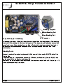
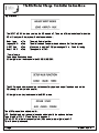
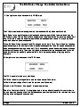
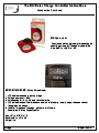
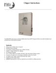
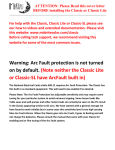
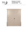
The Kid Solar Charge Controller
Instruction Manual
Features
● MPPT charge controller gives maximum yield for solar
● Standard model can wall or flush mount
● Marine model includes mounting bracket
● Backlit LCD display
● Works as a load controller / Charge controller
● Menu driven system control
● Can be input paralleled for a true 60 Amp single controller
● Conformal coated circuit board for harsh environments
This version of the Kid is for use only with solar installations.
A wind/hydro version is coming soon. Please contact your dealer or MidNite Solar for more
information.
MidNite Solar
1 7722 - 67th Ave NE
Arlington, Wa 98223
www.midnitesolar.com
The Kid Solar Charge Controller Instructions
IMPORTANT SAFETY INSTRUCTIONS
SAVE THESE INSTRUCTIONS - THESE INSTRUCTIONS CONTAIN IMPORTANT SAFETY AND OPERATING INSTRUCTIONS FOR
THE KID CHARGE CONTROLLER MODEL NUMBERS MNKID-B, MNKID-W, MNKID-M-B, MNKID-M-W.
If you do not fully understand any of the concepts, terminology, or hazards outlined in these instructions, please refer installation to a qualified dealer, electrician or
installer. These instructions are not meant to be a complete explanation of a renewable energy system. All installations must comply with national and local electrical
codes. Professional installation is recommended.
GENERAL PRECAUTIONS:
WORKING WITH OR IN THE VICINITY OF A LEAD ACID BATTERY, SEALED OR VENTED IS DANGEROUS. VENTED
BATTERIES GENERATE EXPLOSIVE GASES DURING NORMAL OPERATION. FOR THIS REASON, IT IS VERY
IMPORTANT THAT BEFORE SERVICING EQUIPMENT IN THE VICINITY OF LEAD-ACID BATTERIES YOU REVIEW AND
FOLLOW THESE INSTRUCTIONS CAREFULLY.
If service or repair should become necessary, contact MidNite Solar Inc. Improper servicing may result in a risk of shock, fire or explosion. To reduce
these risks, disconnect all wiring before attempting any maintenance or cleaning. Turning off the inverter will not reduce these risks. Solar modules
produce power when exposed to light. When it is not possible to disconnect the power coming from the Photovoltaics by an external means such as a
combiner, cover the modules with an opaque material before servicing any connected equipment.
Do Not expose to rain or snow. NEVER attempt to charge a frozen battery. Do not smoke around batteries.
When it is necessary to remove a battery, make sure that the battery bank disconnect breaker is in the off position and that the PV breakers, grid
breakers and any other sources of power to the inverter are in the off position. Then remove the negative terminal from the battery first.
To reduce risk of battery explosion follow these instructions and those published by the battery manufacturer as well as the manufacturer of any
additional equipment used in the vicinity of the batteries.
Avoid producing sparks in the vicinity of the batteries when using vented batteries. Provide ventilation to clear the area of explosive gases. Sealed AGM
and Gel batteries do not under normal conditions create explosive gases. Refer to the battery manufacturer's documentation. Be especially cautious
when using metal tools. Dropping a metal tool onto batteries can short circuit them. The resulting spark can lead to personal injury or damage to the
equipment. Provide ventilation to outdoors from the battery compartment when installing vented batteries such as golf cart T-1 05 batteries. The addition
of a spill tray is also a good idea.
Clean all battery terminals. Very high currents are drawn from the batteries; even a small amount of electrical resistance can result in overheating, poor
performance, premature failure or even fire.
Have plenty of fresh water and soap nearby in case battery acid contacts skin, clothing or eyes. Wear complete eye and clothing protection. Always
avoid touching eyes while working near batteries. If battery acid or battery terminal corrosion contacts skin or clothing, wash immediately with soap and
water. If acid enters the eyes, immediately flood with cool running water for at least 1 5 minutes and get medical attention immediately. Baking soda
neutralizes battery acid electrolyte. Keep a supply near the batteries
Do not work alone. Someone should be in the range of your voice or close enough to come to your aid when you work with or near electrical equipment.
Remove rings, bracelets, necklaces, watches etc. when working with batteries, photovoltaic modules or other electrical equipment. Power from an
illuminated photovoltaic array makes a very effective arc welder with dire consequences if one of the welded pieces is on your person.
To reduce the risk of injury, connect only deep cycle lead acid type rechargeable batteries. Other types of batteries may leak or burst, causing personal
injury or damage.
Wiring methods used shall be in accordance with the Canadian Electrical Code, Part I.
Wiring must be done in accordance with the National Electrical Code Article 690 ANSI/NFPA 70. Use Class 1 wiring methods for field wiring connections
to terminals of a Class 2 circuit. Use only 1 4-1 0 gauge AWM wire. Select the wire gauge used based on the protection provided by the circuit
breakers/fuses. Overcurrent protection must be installed as part of the system installation. Refer to the wiring diagrams provided in
this manual for breaker/fuse/GFDI sizes and model numbers.
WARNING : This unit is not provided with a GFDI device. This inverter or charge controller must be used with an external GFDI device as required by
the Article 690 of the National Electrical Code for the installation location.
Use of attachments or accessories not approved by MidNite Solar could result in damage or injury.
Before making any connections verify that the circuit breakers are in the off position including the inverter breaker. Double check all wiring before
applying power.
2 | Page
1 0-268-1 REV A
The Kid Solar Charge Controller Instructions
INSTRUCTIONS DE SÉCURITÉ IMPORTANTES
CONSERVER CES INSTRUCTIONS - CES INSTRUCTIONS CONTIENNENT DES INFORMATIONS
IMPORTANTES POUR UTILISER LE MIDNITE SOLAR THE KID CHARGE CONTROLLER
(RÉGULATEUR DE CHARGE) MODEL NUMBERS MNKID-B, MNKID-W, MNKID-M-B, MNKID-M-W
EN TOUTE SÉCURITÉ.
Avant l’utilisez cet appareil lis et comprends toutes les instructions et avertissements.
Si vous ne comprenez pas l’une des concepts ou des instructions contenu dans cette manuel consulter
un agent spécialisé.
Si des réparations sont nécessaires contactez MidNite Solar pour plus des informations. Danger de
choc électrique et de risque de brulure. Rien à dépanner à l'intérieure du cette appareil. Ne pas ouvrir le
couver. Pour toute réparation ou service d'entretien, consulter un agent spécialisé. Il y’a peut-être
plusieurs sources d’alimentation dans cette system. Débrancher toutes les interrupteurs avant toute
d'entretien où nettoyage.
Ne travaillez pas seul. Quelqu'un devrait toujours être à proximité pour aider en cas d'une situation
d'urgence.
Retirer bagues, bracelets, colliers, montres, et quelles choses comme ça. Il y’a risque des blessures
graves s’il y’a un court-circuit. Cela pourrait ruiner votre journée entière.
Cette appareil n'avoir pas un détecteur des fautes de terre. C'est nécessaire de emploi la protection
contre des fautes de terre a l'extérieure de cette appareil en conformité avec le National Electrical
Code.
Les méthodes de câblage utilisés doivent être conformes au Code canadien de l'électricité, Partie I.
Le câblage doit être fait en conformité avec le National Electrical Code Article 690 ANSI / NFPA 70.
Utiliser des méthodes de câblage de catégorie 1 pour les connexions de câblage sur .des terminaux
d'un circuit de classe 2. Utilisez uniquement des fils de AWM de calibre 1 4-1 /0. Sélectionnez le type de
câble utilisé sur la base de la protection prévue par les disjoncteurs / fusibles.
3 | Page
1 0-268-1 REV A
The Kid Solar Charge Controller Instructions
Table of Contents
Warnings.............................................................................................. 2
The Kid Dimensions............................................................................. 6
Mounting The Kid................................................................................. 6
Stickers................................................................................................ 8
Wiring................................................................................................... 1 3
Load Circuit.......................................................................................... 1 5
Aux Input / Output................................................................................ 1 6
MNBTS Battery Temperature Sensor...................................................1 8
Stacking The Kid.................................................................................. 1 8
Set-Up and Use................................................................................... 20
L.E.D. Legend...................................................................................... 32
Firmware Update................................................................................. 32
Wiring Diagrams.................................................................................. 35
HyperVOC............................................................................................39
Power Graph........................................................................................ 40
Accessories..........................................................................................40
Whiz Bang Jr. Current Monitoring........................................................ 43
Warranty Information............................................................................45
Specifications....................................................................................... 46
Ratings / Fuses.................................................................................... 47
Wall Mount Template............................................................................48
Symbols used in this manual
Ground Symbol
Indicates an earth ground connection.
4 | Page
1 0-268-1 REV A
The Kid Solar Charge Controller Instructions
The parts included in the hardware kit
provide great flexibility for installing
The Kid in many different locations.
Included Hardware kit
9-61 4-1 90° 1 /2" snap-in Conduit adapter (2)*
There are straight and right angle
fittings for flex conduit as well as a
strain relief for power wires and a split
grommet for data wires.
9-642-1 Heyco M3200 Conduit Adapter
6-092-1 Nut for M3200 Conduit Adapter Nut
6-022-1 Split grommet
9-61 4-2 Straight conduit adapter (2)*
9-1 54-1 Micro Shunt (2)
See page 1 9
6-002-1 Kepnut for ground lug
5-1 79-2
9-557-2 Spare Fuse/Jumper (2) USB Hole Plug 9-595-1 Ground lug
* Marine hardware kit Only.
5 | Page
See page 1 7
1 0-268-1 REV A
The Kid Solar Charge Controller Instructions
Mounting the KID:
There are three methods of mounting available for the KID:
1 . In wall mounting.
This is very useful for RV’s, some boats and cabins or just about anywhere you want a built in look.
You will need to insure that the wall is not so thick as to obstruct the wiring that enters through the
bottom surface of the KID. The conduit wire holes in the bottom of the casting are 0.28” (7mm away
from the back mounting flange. So if your wall is more than 0.25” (6.35mm) thick, this may interfere
with accessing the wiring behind the wall. The conduit nut or adapter also takes away from this
narrow wall allowance. You may be able to remove some material from the back surface of the wall
to increase clearance.
Mounting holes are designed for #1 0 (5mm) screws.
The hole cut into the wall must be very accurate. A template is provided at the end of this manual.
The casting on the KID is 8.65” (21 9mm) x 4.54” (11 5mm) with a .400 (1 0mm) radii on each corner.
Mounting holes are designed for a #1 0 (5mm) screw. The center to center dimensions are 8.763”
(222mm) x 4.5” (11 4mm) The KID has a depth of 1 .45” (37mm) from the mounting flange to the
back surface.
A template is provided at the back of this manual.
6 | Page
1 0-268-1 REV A
The Kid Solar Charge Controller Instructions
2. Surface mount.
The Kid can be mounted on a wall using the supplied wall mount adapter. As a minimum you will
need to supply ½” strain reliefs to secure the wires to the casting. Regular metal strain reliefs are
available at any hardware or electrical store. Metal Romex strain reliefs are designed to clamp
down on Romex shielded cable. You will most likely be using individual 1 0AWG conductors and
therefore the outer sheath to protect the conductors will not be there. Be aware that excessive
clamping pressure from the strain relief will bite through the wire insulation and short the conductors
to the case. Not only can this cause fires, it is very hard to trouble shoot.
Locate and twist out the
wire knockouts in the
bottom section of the wall
mount adapter.
Secure the plastic wall mount adapter to the wall
using appropriate screws (not provided). Make
sure the screws are adequate for the weight of
the KID. The wall mount adapter is intended to
use #1 0 (5mm) screws.
Make the wire connections to the terminal block inside the KID, replace the back plate and then
assemble the KID to the wall mount adapter. Use the #1 0 x ¾” Plastite screws provided to secure
the KID to the wall mount adapter. Black units get black stainless steel screws and white units get
natural stainless steel screws.
RIGHT: The Kid surface mounted.
7 | Page
1 0-268-1 REV A
The Kid Solar Charge Controller Instructions
Sticker Identification
1 . Warning-Ignition Protected.
2. Equipment Grounding Terminal.
3. RCM Mark.
4. Caution-Stored Energy.
5. Caution-Connection sequence.
6. Attention-Energie Retenu.
7. Model Number.
8. Do Not Overtighten.
9. Caution-Voltage Present.
1 0. Aux Output.
11 . CE.
1 2. Serial Number for shipping box.
1 3. Negative In/Out separate.
1 4. Caution-Keep out of the rain.
1 5. Torque Ratings.
1 6. Start-up info.
1 7. Danger-Shock/Burn.
1 8. Danger-Don't Touch.
1 9. Charge Battery Types.
20. Ground Symbol.
21 . Avertissement-Arcs/Etincelles.
22. Warning-Arcs/Sparks.
23. Warning Fuse Types.
White Sticker set shown.
Also applies to black Sticker set .
8 | Page
1 0-268-1 REV A
The Kid Solar Charge Controller Instructions
Sticker Placement
Due to the large number of required warnings it is easy to begin to overlook them.
Some of the warnings are actually quite important and good knowledge for the installer and user.
All required labels are supplied. You will find a label identifier on the previous page.
The placement guide below shows where each label goes. Please take the time to read and understand
each label as you place it on the unit.
These warning labels are Required by the the regulatory standards that The Kid has been tested to.
Place the stickers where shown. Some Stickers will be applied at the factory. Some are internal and
number 1 2 will be on the shipping box.
Shock Sticker
Fuse Sticker*
Cautions Sticker*
Spark Warning Sticker
Rain WarningSticker
Connection Sticker
Ground Sticker
Voltage Sticker
Do Not Overtighten
Spark Warning Sticker
Ignition Sticker
Model Sticker*
* Pre-Installed
9 | Page
Battery Type Sticker
1 0-268-1 REV A
The Kid Solar Charge Controller Instructions
Additional Stickers:
In Canada CSA 22.2 No. 1 07.1 -01 requires certain
information to be visible while the unit is in operation.
To satisfy this requirement some additional stickers have
been provided on the wall mount adapter.
These stickers have the same information as those
already on The Kid.
Marine Unit 90° conduit adapters
When using both 90° conduit adapters side by side
it is necessary to remove 1 /8" from the side of each
conduit adapter to allow them to fit so closely together.
1 0 | Page
1 0-268-1 REV A
The Kid Solar Charge Controller Instructions
3. Marine mount.
The third way to mount the KID is with the Marine Mount Bracket.
MNKID-M-BKT-W (White) or MNKID-M-BKT-B (Black) Marine Mounting Brackets.
This bracket comes standard with Marine versions. There are two metal pieces that come with
the Marine Mount Bracket. A collar that mounts to the KID and the Marine mounting bracket base.
Mount the KID to the collar using four 8-32 screws and nuts provided. The kit is available in black
or white.
If your installation is to have wiring go through the bracket, then first remove the knockout holes.
Mount the bracket securely to a suitable surface Using #1 0 (5mm) screws.
The base may be mounted from under or above. Two thin rubber washers are provided that go
between the collar and the bracket. They help keep the KID from slipping after tightening up the
black knobs.
Important!
Mounting bracket may not be suitable for extreme vibration environments.
The Kid has an IP rating of 50 and should be protected from rain, snow or other moisture.
11 | Page
1 0-268-1 REV A
The Kid Solar Charge Controller Instructions
Optional rain Shield .
Required for approved marine applications.
The Kid shown with the optional Rain/Drip Shield.
The rain/drip shield is required for code compliant marine applications.
The addition of the rain/drip shield does not make the Kid weatherproof.
Install the Kid where it will be protected from rain, spray, snow or other moisture.
The use of Loctite ® Threadlocker 222 (Purple) is recommended to prevent the marine mount from
loosening due to vibration.
The Kid should be rotated no more than 1 5º to maintain protection from the rain/drip shield.
1 2 | Page
1 0-268-1 REV A
The Kid Solar Charge Controller Instructions
The Kid Main Electrical Connections
The following pages contain wiring diagrams and system images.
Remove the back cover.
Remove the screw on the middle right of the back cover and gently remove the back cover.
The connections for PV input, Load/Clipper and Battery out are available on the terminal block shown
below, located inside The Kid on the backside of the circuit board.
Observe polarity on all connections.
PV Input: Connections from the solar panels go here.
Load/Clipper: Connections to the controlled load (load control function).
Battery Out: Connections to the battery bank go here.
Torque all connections to 7-9 inch pounds (0.80 - 1 .0 Nm).
Both negatives must be connected for proper operation.
The Kid Terminal Block
+ - + -+ Battery Out
Load
PV Input
Rear View of The Kid with the back cover removed.
Use 75°C Minimum rated copper conductors.
Utiliser uniquement avec conducteurs de cuivre nominale minimale de 75° C
1 3 | Page
1 0-268-1 REV A
The Kid Solar Charge Controller Instructions
Grounding Lug
Grounding points are provided inside and on the back of The Kid.
This ground is inecessary to satisfy the requirements of UL458 Marine and RV standard.
Install the external ground lug as shown below with the hardware supplied.
Be sure to use the #1 0 lockwasher as shown. This is to cut through any paint overspray that might
interfere with making a solid ground connection.
Verify the ground connection using a digital meter with the beep setting. There must be less than 0.1
Ohm of resistance between the ground lug and the back cover mounting screw.
1 0-32 X 3/1 6 Pan Head Screw
#1 0 Lockwasher
Calfastener C 54 S Box Lug
The Kid Back Cover
Verify the ground connection with a meter set
to the beep setting between these two points.
Grounding Lug hardware supplied with The Kid
1 4 | Page
1 0-268-1 REV A
The Kid Solar Charge Controller Instructions
Wiring to the KID
Centered directly above the ½” conduit holes you will find the main 30 amp 6 position terminal block.
This is where you will connect PV input, loads (if any) and the battery bank. The battery bank should use
1 0AWG wire (5.26mm2). On the included wiring diagrams you will notice an external 30 amp circuit
breaker in series with the battery plus wire. This is very important and is a requirement to meet NEC
guidelines for overcurrent and disconnect devices. The battery overcurrent device regardless whether it is
a circuit breaker or fuse must be rated for the DC voltage rating of the battery bank with a minimum of
5000 Amp interrupt rating. Fuses incorporated into the KID are not to be used as these NEC required
overcurrent devices. The internal KID fuses are for internal KID operation only. MidNite Solar
manufactures numerous circuit breaker boxes for this use.
PV input overcurrent devices should follow the NEC guidelines of 1 .56 times short circuit current.
Therefore two 250 watt modules in series results in 8.87 amps of short circuit current (Isc) X 1 .56 =
1 3.83 amps. The NEC allows 1 5 amps through most 1 4AWG wire, so in this case 1 4AWG wire is
sufficient. Long distances (over 30 feet / 9 meters) may want to use larger wire to minimize voltage drop.
Now let’s take those same two solar panels and put them in parallel. This configuration will result in 1 7.7
Isc amps. Multiply this by 1 .56 = 27.6 amps. 1 0AWG wire is rated for 30 amps, so you would need to
switch to 1 0AWG wire for paralleled operation. The NEC requires a disconnect and overcurrent protection
on the PV input. Overcurrent protection can be a fuse or circuit breaker. Thermal circuit breakers require
the same 1 .56 times Isc, but MidNite solar hydraulic/magnetic breakers require only 1 .25 times Isc. All
MidNite din rail and panel mount breakers are hydraulic/magnetic and are rated to hold 1 00% current.
The use of a breaker is typical because you also get the required disconnect at the same time. MidNite
Solar manufactures Baby, Big Baby and Quad boxes to help comply with these requirements.
The wiring diagrams included in these instructions also include another breaker in series with the PV
input breaker. This additional device is a DC-GFP. (ground fault protector). The NEC mandates the use of
DC-GFP’s in all solar systems to help eliminate fires caused from faulty wiring. We find that the best use
for these devices is to find wiring errors made during the initial installation. MidNite Solar manufactures
the MNDC-GFP63 that fits in the Baby and Big Baby box along with a MNPV30 input breaker. The Big
Baby can also hold the battery breaker as discussed above. So one Big Baby box, one MNDC-GFP63,
and two MNEPV30 breakers fit the bill for all NEC required disconnects and overcurrent devices.
This marine unit should be connected to a grounded, metal, permanent wiring system; or an equipmentgrounding conductor should be run with circuit conductors and connected to equipment-grounding
terminal or lead on unit. Connections to unit should comply with all local codes and ordinances.
Connect battery positive and negative first. Then connect array positive and negative. Then apply power
by turning on the external breaker. If the polarity is correct, the unit will power up. If the unit powers up,
and the customer wants to enable the load circuit, they can then install the load fuse. The fuse does not
need to be installed for the unit to function as a charger. If the battery cables are to be removed, remove
power by turning off the external breaker and remove the fuse. Follow this procedure each time the
battery is connected/disconnected. This fuse is supplied but not installed.
Load circuit:
The load circuit is a multi-function circuit. There is no de-rating of the overcurrent device, so if running a
20 amp load. You can use a 20 amp breaker and 1 2AWG wire. You can run a larger load such as a 400
watt inverter by using a 30 amp breaker and 1 0AWG wire. The overcurrent device for the loads can be
housed in a Baby, big Baby or Quad box. See the wiring diagrams at the end of this manual for more
details.
1 0-268-1 REV A
1 5 | Page
The Kid Solar Charge Controller Instructions
Aux input/output:
This 2 position terminal block is the aux input/output. Presently the KID supports only the MidNite
Whizbang Jr battery status monitor to these terminals. The top terminal connects to the single wire
coming from the Whizbang Jr.
As new features are added they will be available at no cost at
http://www.midnitesolar.com/firmwareIndex.php
Do not allow excess
exposed wire
Stacking port
Battery temperature
sensor plugged in
Sample wiring showing PV, Load/Clipper, Battery, Whizbang Jr., BTS and stacking cable.
Wires may exit through either conduit fitting.
Important!
Both the input and output negative
must be connected.
Failure to do so will cause inaccurate
current readings and possible
damage to the unit.
1 6 | Page
One Heyco part # M3200
strain relief is supplied for
the power connections.
One Heyco part # UB-875
bushing is supplied for
other connections.
1 0-268-1 REV A
The Kid Solar Charge Controller Instructions
Chassis Ground connection
The screw, nut and terminal for grounding the chassis are included on all models.
The chassis ground (equipment ground) is required in an NEC compliant system. The chassis of the
KID is isolated from all internal KID circuitry.
Wiring the rest of the system :
Under the “Wiring diagrams” section of this manual there are seven different system configurations.
1 2, 24 and 48VDC systems are shown. These diagrams are based on common solar panels rated
between 230 and 250 watts each, and a VOC of about 37 volts. (60 cell modules). These diagrams
cover 95% of all combinations that will be used with the KID. Other solar panels are available and can
certainly be used with the KID. Study the wiring diagrams to find the one that best suits your needs.
You will see from 2 to 6 solar panels depending on system design and battery voltage. In a 1 2V
system you will be limited to just two of these solar panels. The reason is that the KID has an absolute
maximum output of 30 amps. Power is amps X voltage, so 30 amps output times 1 4 volts (charge
voltage) = 420 watts. A 500 watt PV array would be a good match for a 1 2V system. You can always
start with a smaller PV array and add to it at a later date. Keep in mind that PV voltage and current
need to be matched closely in most cases. See the power graph at the end of this section. Battery
voltage for the KID can be 1 2, 24 or 48 volts, so that means when you jump to a 24V battery bank, the
KID can process twice the power than if it were connected to a 1 2V battery. In the case of a 48V
battery, the KID can process 4 times the power of a 1 2V battery. Twelve volt batteries are used in
marine and RV and very small Renewable Energy systems. When possible, it is better to go with a
higher voltage battery bank, but that is usually not possible in a mobile application.
1 7 | Page
1 0-268-1 REV A
The Kid Solar Charge Controller Instructions
MNBTS Battery Temperature sensor
Standard on Marine versions, optional on All others. The published ratings of most batteries are made
at 77 degrees F (25°C). Mother nature as well as man doesn’t always allow the ambient temperature to
hover around 25°C while charging batteries. Battery temperature sensors are employed on many
sophisticated chargers in order to compensate the charge voltage based on temperature. If you are in
an area where the ambient temperature is relatively stable at this temperature, you do not need a BTS
(Battery Temp Sensor). If you live in Alaska or in the Sahara desert, you will want a BTS. It will prolong
the life of your batteries. The BTS raises the charge voltage when colder than 77 degrees C and
decreases the charge voltage above 77 degrees F.
Temp comp is set for lead acid batteries, but is adjustable for other types in the Battery menu.
Stack port:
The KID stacking port is used for two things. When your power requirements grow and more
charging current is required, you can add a second KID and have it act like a 60 amp controller. This
requires that the PV input and battery output be paralleled, You accomplish this outside of the KID in
a suitable junction box. See page 21 for stacking set-up. Make sure to use wire and breakers of
suitable size for each KID. Since you will now have a 60 amp output capability, you might think that a
single 60 amp breaker after combining the output is acceptable? However, each KID accepts 1 0AWG
wire max. A 60 amp breaker does not protect 1 0AWG wire, so two 30 amp breakers will be required.
The same situation exists for the PV input. Make sure that wires are not too small for the overcurrent
devices.
1 4AWG = 1 5 amp breaker
1 2AWG = 20 amp breaker
1 0AWG = 30 amp breaker
8AWG = 50 amp breaker
6 AWG = 60 amp breaker
1 8 | Page
1 0-268-1 REV A
The Kid Solar Charge Controller Instructions
Stacking Jumpers
MasterStacking Port
Slave Stacking Port
Jumper settings for stacking:
USB Connector
In the upper right corner of the circuit board there are two positions for placing jumpers. If not stacking
(only one Kid) or stacking two Kids leave the jumpers off. The jumpers may be placed on one pin to be
saved for later use. When stacking 3 or more Kids in "Follow Me" mode jumpers should be placed in
both positions on the second and subsequent Kids. The jumpers should be oriented side to side
(horizontally).
Stacking Ports:
Connect a standard four conductor phone cable (Sold separately) between the MASTER jacks of the
first two Kids.
If additional Kids are to be connected, connect a CAT5 cable (sold Separately) from the SLAVE Jack
on the second Kid to the Master Jack the next Kid.
Continue in the same manner, Slave jack of one Kid to the Master Jack of the Next Kid in line. Up to 1 2
Kids may be connected in this manner.
1 9 | Page
1 0-268-1 REV A
The Kid Solar Charge Controller Instructions
Serial communications from the stack port:
In the future you will be able to get serial data from the stack port. You cannot have a stacked pair of
KIDS and serial data at the same time however. Firmware can be downloaded to upgrade the KID
features at http://www.midnitesolar.com/firmwareIndex.php.
Set-Up and Use
These instructions are for firmware revision 1 733. New features are added frequently.
Now that your KID is all wired up, solar panels in place and connected, battery bank installed and any
loads connected, it is time to turn things on.
Get a digital meter. They can be had for as low as $4.00 at Harbor freight, so there is no excuse to not
have one. You will need one if support is ever required.
Check list:
Make sure all breakers are off. You didn’t have them turned on while wiring did you?
Measure the battery voltage to insure you don’t have a bad battery or bad connections. Read from
Battery plus to battery minus to get your nominal voltage. A 1 2V battery should read between 11 .5 and
1 3.00. By the way if it does read below 1 2V, that is not a good sign! Then measure it again at the KID
terminals. It should be the same as at the battery.
Measure the output of the PV array from the PV minus to the PV plus at the point of connection at the
PV input breaker. Then turn the PV input breaker on and measure at the KID terminal block PV+ to
PV-. A 60 cell module should read about 37VDC. Two in series will read about 74. Three in series
should read about 111 . Don’t worry if you are off by 1 0% or so.
Please do make sure that the panels are pointed at the sun, that the sun is completely on each panel
with no shading and you are not inside of a garage. The sun must be illuminating the entire solar
panel (s). You would be surprised how many people don’t understand this concept. Our tech support
people talk to them all the time. It is easy to avoid this situation.
Leave your Load breaker off for the moment.
Turn on the battery breaker. If this is the first time it has been turned on, you will see this:
If your battery voltage is 1 2V, then hit the right arrow key to advance to the next set up selection. If you
have a different battery voltage than what is displayed, then hit the up or down arrow key until the desired
nominal battery voltage is displayed. Once the correct voltage is displayed, hit the right arrow key.
20 | Page
1 0-268-1 REV A
The Kid Solar Charge Controller Instructions
The next set of screens are where you select battery type. Selecting the applicable battery type sets
some important parameters that are specific to different battery chemistries. The first choice is
Flooded. Use the up arrow to see all the choices. Listed below.
Stop on the correct battery type and then hit the right arrow
key. It then takes you to the absorb voltage screen.
21 | Page
1 0-268-1 REV A
The Kid Solar Charge Controller Instructions
When the absorb screen appears, use the up/down arrow to adjust absorb voltage. Consult your battery
manufacturer for their recommended settings. There is no such thing as one setting that fits all flooded
or AGM etc. batteries. Different manufacturers have different requirements. Differences may be subtle,
but the KID is capable of very fine adjustment. There is no reason to guess as to these important
settings. When done, hit the right arrow key to go to the Float settings screen.
Setting the Float voltage is accomplished exactly the same as the previous Absorb voltage. Use the up
down arrows to adjust the float voltage according to your battery manufacturer’s recommendations.
When done, hit the right arrow key to bring you to the Equalize screen.
Default is 1 5.0 volts. This is not high enough to EQ a flooded battery, but not so high that it would hurt
a Gel or AGM style battery which is why the EQ default setting is intentionally set low. Flooded
batteries require periodic Equalizing to reduce sulfation. Consult your battery manufacturers
specifications for a correct EQ setting. If your type of battery does not want to ever be EQ’d, then
simply set the voltage to the Absorb voltage.
When done, hit the right arrow key to bring you to the Input Function screen.
This screen is where you select what type of charge controller you will configure the KID for. Solar
is the most common. Use the up /down arrow keys to select Solar, then hit the right arrow key. The
screen changes to say DATA HAS BEEN SAVED and then switches to a status screen.
22 | Page
1 0-268-1 REV A
The Kid Solar Charge Controller Instructions
Your KID is now set up for all the required settings. There are still two more things to do before it can
start charging.
1.
2.
Turn on the PV input breaker so the KID has PV array voltage applied.
The KID is not yet turned on, so you will need to turn it on. To turn the KID on, you will need to get
to the INPUT Main Menu. Use the right arrow key to go to the INPUT menu and push enter.
Assuming this is a solar controller and assuming that it booted up in the off position, hit the right
arrow key. You will hear the relay click and turn on. Hit the save button. The KID is now on, so hit
the status button and see what it is doing. Use the right/left arrow keys to scroll through the
different status screens.
MAIN MENUS:
The KID has 7 MAIN MENU headings. This section deals with the MAIN MENU headings only.
See INSIDE THE MAIN MENUS for what is inside each of the 7 menus.
Hit the MENU/BACK key. This button takes you to all of the Main Menus. Main menus are something
you want to become familiar with. No matter where you are at in any menu, you can always get to the
Main Menus by hitting this button once or twice.
You scroll through Main Menus from left to right. The left most Main Menu is as follows.
Notice the word BATTERY is in brackets. That means the BATTERY menu will be activated if the
ENTER button is pushed. The BATTERY menu allows you to set all battery charging parameters just
like what was done in the initial set up.
The BATTERY menu has additional adjustments beyond what the initial set up had. After the first time
activating the KID, this is the way to change Battery charging parameters.
The adjustment and settings available inside the BATTERY menu are:
Absorb voltage settings
Float voltage settings
Equalize voltage settings
Amp limits for battery charging and load draw
Temperature compensation adjustability
Temp comp during EQ
23 | Page
1 0-268-1 REV A
The Kid Solar Charge Controller Instructions
Advanced Battery Settings:
Located under the “Battery” menu a submenu labeled “Advanced ”.
This menu contains advanced charge settings.
EndAmps:
Best results are obtained when a Whiz Bang Jr. (Sold Separately) is connected to the kid.
End Amps refers to the amount of current flowing to the batteries. When End Amps are set, this function
will act as a secondary termination to the absorb timer.
The End Amps function works by monitoring the current going into the batteries during the absorb stage.
As the batteries charge, the current needed to maintain the Absorb voltage set-point reduces and
depending on the battery bank type and size there is a current flow level that indicates that the batteries
are full. End Amps are that level, if the current flow goes below the End amps setting for one minute
then the Absorb cycle will be terminated and it will go to Float stage.
Shunt Selection:
Selecting between the internal shunt and the optional Whiz Bang Jr. is found in the “Calibration” menu.
Rebulk:
Rebulk is the Voltage set-point at which the Float stage will terminate and return to Bulk.
In Float, the Kid will return to Bulk if a load placed on the battery bank reduces the battery bank voltage
below the Rebulk set point for two minutes.
24 | Page
1 0-268-1 REV A
The Kid Solar Charge Controller Instructions
Load Menu:
All loads are connected to the LOAD terminals of the main KID terminal block. Programming the Load
Functions determine how and where the load is connected. (Battery vs. Input).
Hitting the right arrow key brings up the INPUT menu.
Scrolling to the right will bring you to the LOAD menu.
This is the LOAD Main Menu. It allows numerous types of load functions.
You first select if you are configuring Battery connected loads or Input connected loads.
Battery connected load modes are:
Manual
Night Light
Day Light
PWM Divert
Float On
Float Off
Diversion
Toggle
off/auto
off/auto
off/auto
off/auto
off/auto
off/auto
off/auto
off/auto
Use the up and down arrow keys to move through the options.
Press the right key to select. Pressing the left key will de-select.
Press menu Back when done.
25 | Page
1 0-268-1 REV A
The Kid Solar Charge Controller Instructions
Low Battery Disconnect:
The kid includes an adjustable Low battery Disconnect function which allows the user to set an
absolute discharge limit when using a daily function such as Night Light and the life of the batteries
doesn't want to be compromised, it also includes a reconnect voltage set point or it could be
reconnected when Float has been reached, ensuring that the batteries have been fully charged after
a LBD (Low Battery Disconnect).
If a LBD state has occurred the blue LED will blink slowly.
To set up these parameters:
-Press Menu Back button
-Scroll to the right and select <Load> and press Enter
-Press the Setup button
-If OFF appears under the names Lowbatt and Reconn it means the feature is currently disabled.
-Press the Right button to enable the function, now two numbers will appear under the names
-Press the Left, Right, Up and Down keys to adjust the voltages as needed for your battery type
-To enable reconnect on Float stage go to Reconn and Press the Right key again and the word
FLOAT will appear under Reconn (Float voltage can be configured in the Battery menu).
-Press the Save button to keep the changes on non volatile memory of The Kid.
Refer to the battery manufacturers recommended settings.
Input connected loads:
Clipper Mode:
The INPUT selection will allow the input to be connected to a voltage limiter called a CLIPPER.
Sold separately. This special CLIPPER mode is not used for solar installations.
Note:
A Solar kid must not be used for wind or hydro installations. Damage to the unit may result from
attempting to use a solar Kid for wind/hydro systems.
A wind/Hydro version of the Kid is coming soon. Please contact your dealer or MidNite Solar for more
information.
26 | Page
1 0-268-1 REV A
The Kid Solar Charge Controller Instructions
Input Menu:
The INPUT MENU is where you turn the KID on and off. There are different selections for how the
KID will track your Solar,system. Selections are below:
Solar Learn
Legacy P&O
U-SET Voc
Solar1 O&P
off/on
off/on
off/on
off/on
The main Solar algorithm
The old tried and true perturb and observe. Not fast, but good
Allows you to pick the PWM percentage of Voc. Good for testing
The opposite of P&O
* Future feature
Press Menu Back when done.
Hit the right arrow to advance to the AUX MAIN MENU .
The AUX menu is where you set up various auxiliary input and output functions such as the
Whizbang Jr. Battery status monitor.
Hit the right arrow key to advance to the MISC menu.
The MISC menu allows adjustment for:
LCD Backlight and contrast controls can be adjusted with the up/down buttons
Temp Status of CPU, FET and Battery in degrees C
LED MODE BCM (battery capacity meter) Rick mode (minimal lights) and Off
Timer Shows time accrued.
27 | Page
1 0-268-1 REV A
The Kid Solar Charge Controller Instructions
Hit the right arrow key to advance to the COMM menu.
The COMM menu is where stacking is set up. Your choices are Bully Mode and Follow Me.
Bully Mode: is true paralleling where the inputs and outputs are paralleled. You are allowed only two
KIDS in Bully mode. This is a Master/Slave configuration. The Master bullies the slave into doing what it
says. Follow Me is where the outputs are paralleled, but each input has its own PV array. Bully mode
only works when two kids are connected.
Follow Me Mode: When any one of the KIDs changes state, Absorb, Time, Float or Equalize it sends a
signal downstream to the next one to follow me and also change state. Then the second one sends the
same message downstream and so on until it finally comes back around the communications circle and
all units are in the new state. There is no limit to how many controllers can be connected in Follow Me
mode. Both Follow Me and Bully mode are MidNite Solar exclusive methods of applying multiple
controllers.
Hit the right arrow key to advance to the TECH menu.
The TECH menu is for tech savvy individuals.
Calibrate the battery voltage offset to read the same as your Fluke meter.
Calibrate the Input voltage offset to read the same as your Fluke meter.
Upload new firmware. See page 21 for update instructions.
Reset to factory defaults. Setting things back to factory defaults is useful after your brother in
law was observed messing with all the buttons and you can’t trust what he did. So, reset and start over
entering all the settings you know you want.
28 | Page
1 0-268-1 REV A
The Kid Solar Charge Controller Instructions
AntiClick Sensitivity:
This setting refers to the input voltage from the panels that the Kid will sweep down to from VOC
when trying to figure out if there is enough power for the unit to turn on, the higher the number is set
to the less the relay will click(less sensitive) at sunrise and sunset, but if the number is set too high
then, the unit might not turn on even when there is enough power available to charge the batteries.
The lower that the number is set the unit will click more frequently, and may turn on sooner (with less
power available). If you do not understand this setting, do not change from the factory default setting
(8.0), unless instructed from MidNite Solar personal Tech Support.
To adjust the settings:
*Press main Menu
*Scroll to the right then select TECH and press Enter
*Select Calibrate and press Enter
*Press the right arrow until AntiClick Sensitivt is on the top line of the LCD
*Use the Up and Down buttons to adjust to the desired setting
*Press the SAVE button to keep the settings.
29 | Page
1 0-268-1 REV A
The Kid Solar Charge Controller Instructions
STATUS BUTTON:
There are a few status screens available at the touch of the Status button.
The first (left) screen shows:
The 9.5a as depicted above represents the PV array output current.
BULKMPPT shows the state that the charger is in. BULKMPPT means the KID is going all out to put all
available energy into the batteries.
Other states are:
RESTING This is what happens when the PV array voltage is too low to do any charging.
The 1 2.7V represents battery voltage.
The SOLAR shows it is in Solar mode.
The 257W shows the instantaneous wattage going into the battery.
push the right arrow key to bring up the second status screen shown below.
This second status screen is showing the PV array voltage and battery voltage. The PV array voltage
corresponds to the Max power voltage from the PV array for the present conditions.
Push the right arrow key to bring up the third status screen.
This third status screen is showing.
Note: Some features listed in this manual are not yet functional. Keep your eye on
www.midnitesolar.com for updates in KID firmware.
30 | Page
1 0-268-1 REV A
The Kid Solar Charge Controller Instructions
Setting up The Kid for use with a Whiz Bang Jr. (Sold separately)
State Of Charge:
The Kid in conjunction with the Whiz-Bang JR. offer a real battery S tate Of C harge meter.
There is some set-up before using the WBJr. It is necessary to enter values for Battery bank size in AmpHours, battery efficiency, Battery temperature compensation reference, and percentage of change per
degree C. Refer to the battery manufacturer's documentation for these values.
To enable the WBJR on The Kid:
Press Main Menu button.
Scroll to the right, Until Aux is in shown in brackets, <AUX> Press Enter.
When the display shows FUNCTION: press the right or left key until WBJR is selected.
Press the Right button until the * is next to Auto.
Press the SETUP button to setup the SOC portion.
Entering battery bank information:
Battery Capacity: This is the first screen after you press the SETUP button, Battery Capacity can be
obtained from your battery manufacturer, this is the total capacity of the battery bank.
Use the up and down buttons to adjust the battery capacity of the bank.
Press the Right button to go to the next set up.
Battery Efficiency:
Batteries are not 1 00 percent efficient and some loss does occur. This setting will improve accuracy
by taking this inefficiency into account. Battery efficiency will be different between Manufacturers and
will lower with age, 94% is a good starting point for most battery banks. Your battery bank will reach
1 00% charge as soon as it hits float stage.
Use the up and down buttons to adjust the battery efficiency of the bank
Press the Right button to go to the next set up.
Battery Temperature Reference: This is a reference temperature used as a starting point for
temperature based charging voltage adjustments. This is the temperature at which the battery
manufacturer considers the temperature compensation to be zero, usually this will be 25°C, but it
may vary by manufacturer and battery type.
Use the up and down buttons to adjust the battery temp ref of the bank.
Press the Right button to go to the next set up.
Battery Change %: the change of battery capacitance in percentage above and below of the
temperature reference, usually will be 1 %.
Use the up and down buttons to adjust the battery capacity change percentage.
Press the SAVE button to save the whole set up.
Press the Status button and then scroll to the right to view the WBJR SOC screen.
This screen will show you the Output current going straight to the batteries after the loads, also the
SOC in percentage of the battery bank and also the Amp hours remaining on the batteries.
31 | Page
1 0-268-1 REV A
The Kid Solar Charge Controller Instructions
The Kid's L.E.D.s.
RFC - Received Full Charge. The
battery has received a full charge.
1 WK - One Week. It has been one
week since a full charge.
2WK - Two Weeks. It has been two
weeks since a full charge.
FLT - Float. The battery is in float
charge.
OVR - Over Voltage. The kid has
detected an overvoltage.
ERR - Error. The kid has stopped
due to an error.
CLP - Clipper. The kid is in Clipper
Mode.
The Kid has several L.E.D.s to indicate
modes and errors.
Not all L.E.D.s are implemented at this
time.
Firmware Update
To do a firmware update on the kid you will need the following:
- A laptop or PC with Windows XP/7/8/8.1 or Linux.
- A USB Mini-A cable (not included).
Procedure:
- Go to http://www.midnitesolar.com/firmwareIndex.php and download the latest firmware file.
- Save the file to a known location on your PC (eg. Desktop \).
- Plug in the USB cable to the Kid connector located on the bottom of the unit.
- Plug the other end into an available USB port on the PC.
- Go to MAIN Menu on the Kid And scroll to the right to the TECH menu and press Enter.
- Press the down arrow key until Firmware Update is selected and press Enter.
- After 5 sec the unit will turn off and display FIRMWARE UPDATE.
- A new empty drive will appear in your PC, open it.
- Drag the downloaded file to this empty drive.
- The first green light should start blinking on the Kid and "UPDATING...' should appear on the
second line.
- It will take up to 2 minutes to update the kid.
- The unit will reboot with new updated firmware.
- Unplug the USB cable.
32 | Page
1 0-268-1 REV A
The Kid Solar Charge Controller Instructions
Password protected settings:
UL standards mandate that only qualified people be allowed to change critical settings. We have
determined that people that have read and understood this much of the manual are qualified to change
critical settings.
Changing some of the settings available on The Kid can result in hazardous conditions such as, battery
charger, EQ, Temp Comp and load settings. If you do not fully understand these functions and features
contact your dealer.
Password:
Settings like Battery, input, load settings, calibration and Aux settings are password protected. When the
password is entered it allows 1 0 min for the user to adjust protected settings.
Entering the password:
Press Main Menu ,
Select MISC and press Enter,
Select Password and press Enter,
Select Yes .
When prompted, the Password is 1 42.
Manual EQ:
Manual EQ allows the user to trigger an Equalize (EQ) cycle manually.
There are two parameters to set before you can equalize, EQ voltage and EQ time.
Refer to the battery manufacturer's recommendations for equalizing voltages and times.
To set EQ parameters:
Press Main Menu and select Battery,
Go to EQ and press Enter,
Press the SETUP Button to adjust the EQ Voltage and Time.
To start a manual EQ cycle:
Press Main Menu and select Battery,
Go to EQ and press Enter,
Select START,
The EQ Cycle will begin.
LCD Power Saving modes:
There are 3 different LCD Power settings that can be chosen by the user, they function as follows:
ECO: Eco mode is the default mode. This mode will turn off the Backlight after 5 min of no user input on
the keypad. Turning the backlight off helps reduce the idle power of the Kid by 1 /3 of a watt. This mode
will also return the menus to the Main Status menu after 5 minutes has elapsed.
NRML: Normal LCD mode keeps the Backlight Setting as set by the user, so if the Backlight is set to on
the Backlight will stay on. The backlight draws 1 /3 watt, so it isn’t a big power drain to leave it on.
MAX: Max LCD power saving will turn off the LCD after 5 minutes of no user input, this is useful to
minimize the power consumption of the kid when installed on unattended sites.
For any mode, idle time is set to 5 minutes. To turn the backlight back on, simply press any key and the
LCD will come back on.
33 | Page
1 0-268-1 REV A
The Kid Solar Charge Controller Instructions
Backlight/Contrast:
to adjust the backlight and contrast of the LCD, press the SETUP button in the LCD Power Savings
Screen. Use the up and down buttons to adjust them.
LED MODE:
Located under the MISC menu, the LED mode can be set to several different modes, some useful and
some just for fun.
NRML: this mode will employ all the available LEDs as indicators, The top 3 LEDs refer to the Battery
Capacity Meter function on the kid that indicates to the user the current battery status at a glance (refer
to BCM Section for more info). The FLT LED will come on when the unit goes to Float. It will blink
Slowly when the unit goes to Float MPPT. This mode will also use the Warning (OVR) LED to indicate
when there is an anomaly on the unit, such as Over Voltage or Current Limit. The ERR LED is also
active to indicate Faults on the system. The CLP LED will come on when the Load is active and it will
blink to indicate a warning on the load circuit.
BCM: The BCM function on the LEDs will only employ the top 3 BCM LEDs and the OVR and ERR
LEDs.
RICK: this mode is also known as minimal LED usage, since it will only use the Warning and Error
LEDs.
PLAY: this mode is great for special occasions where you want to Show off your Kid’s fun side, it will
trail the LEDs from top to bottom as long as this mode is selected.
TEST: Useful to verify that all the LEDs are functioning.
OFF: will keep the LEDs OFF, except for the ERROR LED.
Load Current Limit:
The current limit on the load can be set by the user. Whenever the user current limit is reached the load
will turn off for about 1 0 seconds, it will then try again. If the Max allowable current (30 amperes) is
exceeded, the Load will be turned off and kept off for 3 minutes. It will retry, if the overload condition is
still present, it will stay off for another 3 minutes. The Kid will continue to cycle until the overload
condition is removed. In the Load Status screen it will Say “Over Current! ” and the blue LED will blink.
To adjust the Load Current limit:
• Press Main Menu , select Battery and Press Enter.
• Select AmpLmt and press Enter.
• Select Load and use the Up and down buttons to adjust the limits.
•
Press SAVE Button to save the adjustment.
Scrolling Status Screens: When the Kid has no user input for 5 minutes the Screen will automatically go
to the status Screen and scroll though all status screens one by one every 3 seconds or so. It was
designed so it would not interfere with the user setting the unit parameters, but if this is not what you
want your unit to do you can always disable this feature:
Press Menu Back and scroll to the “MISC” menu and press Enter
Select “LCD” and press Enter and Scroll to the right to select “Status Scroll?”
Press the down key to Disable
Scroll to the left and select the “LCD Power Mode”
Press Save .
34 | Page
1 0-268-1 REV A
The Kid Solar Charge Controller Instructions
Wiring Diagrams
1 2 Volt System
with two solar
panels in series
Important!
Both the input and output negative must be
connected.
Failure to do so will cause inaccurate current
readings and possible damage to the unit.
1 0-268-1 REV A
35 | Page
Important!
Both the input and output negative must be
connected.
Failure to do so will cause inaccurate current
readings and possible damage to the unit.
1 2 Volt System
with two solar
panels in
parallel
The Kid Solar Charge Controller Instructions
24 Volt System
with two solar
panels in series
Important!
Both the input and output negative must be
connected.
Failure to do so will cause inaccurate current
readings and possible damage to the unit.
1 0-268-1 REV A
36 | Page
Important!
Both the input and output negative must be
connected.
Failure to do so will cause inaccurate current
readings and possible damage to the unit.
24 Volt System
with three solar
panels in
Series
The Kid Solar Charge Controller Instructions
24 Volt
System with
two strings of
two panels
Important!
Both the input and output negative must be
connected.
Failure to do so will cause inaccurate current
readings and possible damage to the unit.
1 0-268-1 REV A
37 | Page
Important!
Both the input and output negative must be
connected.
Failure to do so will cause inaccurate current
readings and possible damage to the unit.
48 Volt System
with three solar
panels in series
The Kid Solar Charge Controller Instructions
48 Volt System
with two strings
of three panels
Important!
The string sizing tool is at
www.midnitesolar.com
Both the input and output negative must be
connected.
Failure to do so will cause inaccurate current
readings and possible damage to the unit.
1 0-268-1 REV A
38 | Page
Important!
Both the input and output negative must be
connected.
Failure to do so will cause inaccurate current
readings and possible damage to the unit.
Two Kids
paralleled with
stacking cable
The Kid Solar Charge Controller Instructions
HyperVOC
The Kid includes HyperVOC
a non-operative VOC safety zone over and
above the maximum input voltage
Why do you need HyperVOC?
On cold mornings PV panels will put out full voltage even before you can see the
sun. Ambient light may not have much current behind it but it does have voltage
that may exceed the operating voltage limit of the controller, resulting in damage to the controller.
The fact that there is no power behind the output voltage means that the controller will not be able to
turn on and drag the panels down from VOC to max power voltage.
The controller requires a few watts of power coming in from the PV panels to overcome
its internal power requirements. While the controller is waiting for enough power to
wake up, the PV array is at its highest output voltage. This is very dangerous if the
maximum operating voltage of the controller is exceeded.
The Kid Solar controller gives you bonus headroom for those cold mornings that
would potentially destroy any other controller. We have advised thousands of customers
to play it safe in conditions like our example above. MidNite has a unique characteristic
of the circuitry that allows it to go beyond the maximum operating voltage for
these conditions, it’s called HyperVOC.
Do not abuse the HyperVOC zone though. For example, let’s take a Kid configured
with 4 modules in series that have 36.9 VOC, 4 x 36.9 = 1 47.6. In Alberta with a
-32°C temperature, the max VOC will reach 1 81 .54. This is well within the HyperVOC
zone on a 48V battery bank.
Above: HyperVOC voltage limits above normal
operating voltage.
Right: Solar Panel VOC adjustments by
temperature.
39 | Page
1 0-268-1 REV A
The Kid Solar Charge Controller Instructions
PV Voltage levels shown are maximum values.
VOC will be 20% higher.
Accessories
Below are optional accessories and accessory kits.
MNKID-BREAKER-30A
30 Amp replacement circuit breaker for The Kid.
40 | Page
1 0-268-1 REV A
The Kid Solar Charge Controller Instructions
Accessories Continued
MNKID-ASSY-KIT-B (Black) or MNKID-ASSY-KIT-W (White) Accessory kit
Kit includes:
Black or white mounting bracket
Flexible conduit
Straight and 90° Conduit fittings
MNBTS Battery temperature sensor
Hardware to attach mounting bracket to The Kid
MNKID-WMB-B (Black) or MNKID-WMB-W (White) Wall Mount kit
Kit includes:
Black wall mounting bracket
Hardware to attach mounting bracket to The Kid.
41 | Page
1 0-268-1 REV A
The Kid Solar Charge Controller Instructions
Accessories Continued
MNHydrometer
Easy to use battery hydrometer for checking the
specific gravity on all "Flooded" style batteries.
Size: 5.25"L x 4.25"W x 1 .5"D
MNBCM / MNBCMS : Battery Status Monitor
1 . LEDs that correspond to battery voltage
2. Voltage accuracy +- .05%
3. Auto sensing for 1 2, 24, 36, and 48 volt batteries
4. LED indicators show if batteries have received a full charge recently, longer than one week or
longer than two weeks
5. Ideal for "at a glance" readings - golf carts, forklifts, etc.
Description: Battery Capacity Meter
Size 4.5"L x 3.75"W x 1 "D
Box Size 5"L x 4"W x 2"D
Weight 1 Lb.
42 | Page
1 0-268-1 REV A
The Kid Solar Charge Controller Instructions
Accessories Continued
Whiz Bang Jr.:
The Whiz Bang Jr. is designed to work with The Kid to give accurate battery status.
The Whiz Bang Jr. keeps track of Amp-Hours going into and out of the battery.
Simple one-wire installation.
Shunt not included.
The Whiz Bang Jr can also provide shunt access for co-operative products.
43 | Page
1 0-268-1 REV A
The Kid Solar Charge Controller Instructions
Optional Circuit Breakers and Accessories
Quad
Big Baby
The Big Baby is an aluminum
powder coated breaker enclosure
that holds four DINRail breakers.
The Quad is an aluminum powder
coated breaker enclosure that holds
four panel mount breakers.
63 amp 1 50VDC din rail mount DC
ground fault protector (NRTL listed
breaker assy).
NEC2008 requires DC-GFP’s on all
solar installations
More circuit breakers and
accessories available at
www.midnitesolar.com
MNDCGFP-63
MNEPV
Breaker
1 50VDC din rail mount breaker (1 3mm wide).
MNEPV evaluated by ETL to 1 50VDC.
1 50VDC ETL listed in the US and Canada
1 0,000 AIC.
MNEDC
Breaker
DC Panel mount breaker available
up to 1 00 amps.
MNEAC
Breaker
1 20V AC DINrail breaker available
in a wide range of Amperages.
44 | Page
1 0-268-1 REV A
The Kid Solar Charge Controller Instructions
Warranty
MIDNITE SOLAR INC. LIMITED WARRANTY
MidNite Solar Power electronics, sheet metal enclosures and accessories
MidNite Solar Inc. warrants to the original customer that its products shall be free from defects in
materials and workmanship. This warranty will be valid for a period of five (5) years for all products
except the MNKID Charge Controller which will be two (2) years.
At its option, MidNite Solar will repair or replace at no charge any MidNite product that
proves to be defective within such warranty period. This warranty shall not apply if the
MidNite Solar product has been damaged by unreasonable use, accident, negligence,
service or modification by anyone other than MidNite Solar, or by any other causes
unrelated to materials and workmanship. The original consumer purchaser must retain
original purchase receipt for proof of purchase as a condition precedent to warranty
coverage. To receive in-warranty service, the defective product must be received no later
than two (2) weeks after the end of the warranty period. The product must be accompanied
by proof of purchase and Return Authorization (RA) number issued by MidNite Solar.
For an RMA number contact MidNite Solar Inc., 1 7722 67th Ave NE, Arlington, WA 98223 (360) 4037207.
Purchasers must prepay all delivery costs or shipping charges to return any defective MidNite Solar
product under this warranty policy. Except for the warranty that the products are made in accordance
with, the specifications therefore supplied or agreed to by customer:
MIDNITE SOLAR MAKES NO WARRANTY EXPRESSED OR IMPLIED, AND ANY IMPLIED
WARRANTY OF MERCHANTABILITY OR FITNESS FOR A PARTICULAR PURPOSE WHICH
EXCEEDS THE FOREGOING WARRANTY IS HEREBY DISCLAIMED BY MIDNITE SOLAR AND
EXCLUDED FROM ANY AGREEMENT MADE BY ACCEPTANCE OF ANY ORDER PURSUANT TO
THIS QUOTATION. MIDNITE SOLAR WILL NOT BE LIABLE FOR ANY CONSEQUENTIAL DAMAGES,
LOSS OR EXPENSE ARISING IN CONNECTION WITH THE USE OF OR THE INABILITY TO USE ITS
GOODS FOR ANY PURPOSE WHATSOEVER. MIDNITE SOLAR’S MAXIMUM LIABILITY SHALL NOT
IN ANY CASE EXCEED THE CONTRACT PRICE FOR THE GOODS CLAIMED TO BE DEFECTIVE
OR UNSUITABLE.
Products will be considered accepted by customer unless written notice to the contrary is
given to MidNite Solar within ten (1 0) days of such delivery to customer. MIDNITE SOLAR is not
responsible for loss or damage to products owned by customer and located on MIDNITE SOLAR’S
premises caused by fire or other casualties beyond MIDNITE SOLAR’s control. This warranty is in lieu of
all other warranties expressed or implied.
MIDNITE SOLAR INC. 1 7722 67TH AVE NE ARLINGTON, WA 98223
Email:
[email protected]
PH: 360-403-7207 FAX: 360-691 -6862
45 | Page
1 0-268-1 REV A
The Kid Solar Charge Controller Instructions
46 | Page
1 0-268-1 REV A
The Kid Solar Charge Controller Instructions
Ratings
Max Input Voltage PV-------------------------------------------------------------1 62 VDC Non-Operating
Max Operating input Voltage PV----------------------------------------------- 1 50 VDC
Max Input Current PV-------------------------------------------------------------30 Amps DC
Max Output Current--------------------------------------------------------------- 30 Amps @ 25°C*
Max Input Short Circuit Current------------------------------------------------ 30 Amps DC
Max Input source Backfeed----------------------------------------------------- XX
DC Output Voltage-----------------------------------------------------------------1 2-64 VDC
Input Battery Voltage--------------------------------------------------------------1 2, 24 or 48 VDC
Input Battery Voltage Range---------------------------------------------------- 9-64 VDC
Operating Temperature Range------------------------------------------------- XX° to XX°
Output Temperature Derating---------------------------------------------------XX mV/°C
*Derated to 20 Amps @ 40°C.
Fuses / Overcurrent protection.
Replace fuses with the same type and ratings: Type ATC 32V 30 Amps Max.
The fuses provided in The Kid are for supplemental protection. External overcurrent protection as
required as part of the installation.
47 | Page
1 0-268-1 REV A
4.50
8.763
9.275
Photocopies of the template may not be accurate and should be avoided.
To use this template:
Remove template from the manual and secure to the wall with a low tack tape such as scotch or masking tape.
Other tapes are more likely to stick to the paint when they are removed. Remove all tape within 24 hours.
Make sure that the template is flat and not crooked.
Use a large drill inside the cut-out area to create an entry point for the saw. Use a drywall or jig saw and cut along the dotted lines
using caution especially around the corners.
Drill the four corner holes with the smallest drill that will work with your hardware. Use caution to avoid breaking through to the large
cut-out area.
Put The Kid in place and secure with appropriate hardware.
4.54
1 0-268-1 REV A
5.01 0
48 | Page
8.675
The Kid Solar Charge Controller Instructions
Wall Mounting Template