1
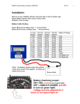
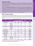
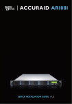
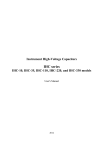
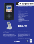
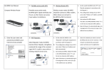
Just the Facts
MidNite Solar Classic Lite
Quick Start Guide 07/05/12
This “Quick Start” is intended to be a supplement to the Classic owner’s manual. It is intended to give the basics of
setting up your new Classic Lite, when installed in a typical installation. Please refer to the Classic Owner’s Manual
(Included DVD or visit www.midnitesolar.com) for all advanced features, safety warnings and specifications.
Este manual también está disponible en Español. La versión en Español puede encontrarse en nuestra pagina web
en la ficha Documentos y haga clic en Manuales.
Ce manuel est également disponible en français. La version française peut être trouvé sur notre site web sous
l'onglet Documents, puis en cliquant sur les manuels.
Just the Facts for the Classic Lite (continued)
The MidNite Solar Classic charge controller conforms to UL 1741, Safety for Inverters, Converters, Controllers
and Interconnection System Equipment for Use With Distributed Energy Resources, Second Edition, May 7,
1999 with revisions through January 28, 2010 and
CAN/CSA C22.2 No. 107.1: 2001/09/01 Ed: 3 (R2006)
Notice of Copyright
MidNite Solar's Classic charge controller User’s Manual
Copyright ⓒ 2010, 2011and 2012 all rights reserved.
MidNite Solar Inc. reserves the right to revise this document and to periodically make changes to the content hereof
without obligation or organization of such revisions or changes unless required to do so by prior arrangement.
Disclaimer
Unless specifically agreed to in writing, MidNite Solar Inc.
(a) Makes no warranty as to the accuracy, sufficiency or suitability of any technical or other information provided in
its manuals or other documentation.
(b) Assumes no responsibility or liability for loss or damage whether direct, indirect, consequential or incidental,
which might arise out of use of such information. The use of any such information will be entirely at the user's risk.
Contact Information
Telephone: 360.403.7207
Fax:
360.691.6862
Email:
[email protected]
Web:
www.midnitesolar.com
2|Page
10-208-1
REV: A
Just the Facts for the Classic Lite (continued)
Contents
Inside view of the Classic ............................................................................................................................................ 4
Ground fault ............................................................................................................................................................... 6
Non Solar inputs to the Classic Lite........................................................................................................................ 6
Wiring the Classic Lite ............................................................................................................................................... 7
LED Modes and Faults ............................................................................................................................................... 8
Dip Switches......................................................................................................................................................... 9
Battery voltage and time settings ..................................................................................................................... 15
Using MNGP Remote to program a Classic Lite ........................................................................................... 16
Programming the Lite with a Networked Standard Classic ......................................................................... 16
Programming the Lite with the Local App ..................................................................................................... 17
Clearing Faults .......................................................................................................................................................... 17
Explanations of Solar and Legacy ........................................................................................................................... 17
Troubleshooting ........................................................................................................................................................ 19
3|Page
10-208-1
REV: A
Just the Facts for the Classic Lite (continued)
Inside view of the Classic
Take care when removing the front cover from the Classic. The LED display panel (MNLP) may be attached to the
main circuit board with a blue phone style cable as seen in Figure 1 below if this is not the first time being opened.
The cable is not plugged in from the factory. Unplug one end or the other and set the Front cover aside during
wiring. When replacing the cover, be sure not to pinch the cable between the cover and the case and that the cable
does not interfere with the components inside. You will also note the use of the top jack. For explanation of the
other 2 jacks and networking diagrams please refer to the Classic User’s Manual (DVD).
Figure 1
4|Page
10-208-1
REV: A
Just the Facts for the Classic Lite (continued)
Figure 2
In Figure 2 above we show from Left to Right, the Ethernet connection to your Router or wireless bridge, USB
cable for updating firmware and the Battery Temperature sensor. On the blue terminal block from left to right
Battery positive, common negatives and DC input positive. You only need to bring a single Negative conductor to
the Classic if you have landed PV- onto the battery negative buss in the E Panel. Both can be used if preferred.
5|Page
10-208-1
REV: A
Just the Facts for the Classic Lite (continued)
Ground fault
There is a 2 pin header to the right of the blue terminal block for Ground Fault Protection as seen below. The
supplied jumper must be installed across both pins for the GFP to operate. The Lite is shipped with this jumper in
the open position. For GFP operation, the jumper must be placed over both pins. Figure 3 shows the GFP jumper
pins with the shorting plug being installed. Figure 4 shows the small black shorting jumper. This will be used to
jump the 2 pins and enable Ground Fault Protection. (Dime not included)
Figure 4
Figure 3
Non Solar inputs to the Classic Lite
The Lite will accept a wide variety of DC inputs from sources like Solar, Wind, Hydro, Fuel Cells ETC. One of the
biggest concerns when hooking the Lite to alternative sources of DC is the input Voltage.
Exceeding the Lite's Voltage window will cause damage to the Lite.
If the source is unregulated and can exceed the Lite's maximum input voltage, a Clipper will be needed to assure the
Lite never has its voltage ratings exceeded.
Note: The Lite will need to be programed in “Custom Mode” for all applications other than Solar.
For more information on alternative inputs, please consult the Classic owner’s manual or contact technical support
[email protected] or 360-403-7207
6|Page
10-208-1
REV: A
Just the Facts for the Classic Lite (continued)
Wiring the Classic Lite
Figure 5
Figure 5 shows a basic wiring diagram for installing the Classic on an E Panel. Some installations may vary. Please
consult the Classic Owner’s Manual for other diagrams. There are 2 jumpers and a 4 position terminal strip (Seen in
the yellow oval above) for Aux 1 and 2 please refer to the Classic owner’s manual for details on how to connect and
use these.
7|Page
10-208-1
REV: A
Just the Facts for the Classic Lite (continued)
LED Modes and Faults
The Lite control panel (MNLP) has 6 status LEDs to indicate various modes of operation as well as faults.
There are 3 behind the small window on the upper left.
The top Orange status LED will light solid to indicate that the controller is in Bulk Charge mode.
The center Yellow status LED will light solid to indicate that the controller is in the Absorption stage.
The lower Green LED will light solid to indicate that the controller is in Float and blink slowly to indicate the
controller is Resting due to low light.
All 3 of these status LED’s will blink slowly to indicate “Wrong Code” please see the trouble shooting
section for help with this.
There are also LED indicators for Current limit, Ground Fault and Equalize.
All LEDs blinking slowly indicate a loss of communication with the Classic. Check that the cable is
plugged in to the top Jack on the Classic. If error persists try another cable or call Tech support for
assistance.
Figure 6
8|Page
10-208-1
REV: A
Just the Facts for the Classic Lite (continued)
Programming
There are four separate ways to program a Classic Lite.
1-The programming is done using Dip Switches under the front cover of the MNLP.
2-The Classic Lite can be programmed with an independent MNGP.
3-The Lite can be Networked with a standard Classic and programmed using the standard Classic’s MNGP
4-The Classic Lite can be programmed using the Local App (Through the Ethernet connection) software included
on the DVD or available at www.midnitesolar.com
Dip Switches
Below you will find an Explanation of the Dip switches and the values associated with their settings. Up is on and
down is off on the switches. To access the Dip switches you need to remove the front cover on the Lite display
panel. Firmly grasp the left and right side of the cover and slide it off as seen in Figure 7.
Figure 7
9|Page
10-208-1
REV: A
Just the Facts for the Classic Lite (continued)
Now you will need to use the supplied tool (Toothpick) to place all 15 switches in the correct position. All the
information on the switches can be found on the labels on the MNLP as well as in Table 1 and Table 2 below. Keep
in mind if any of the switches are set to Custom the Lite display becomes a LED display only and you will need to
use the included PC software or a MNGP to program the Classic. Please see the Appendix of the Classic Owner’s
Manual for info on using the “Local App” software in conjunction with a PC.
Note: The Classic Lite will need to be programed in “Custom Mode” for all applications other than Solar.
Figure 8
10 | P a g e
10-208-1
REV: A
Just the Facts for the Classic Lite (continued)
Mode: Section1, Switches 1 and 2
On Section 1, the first 2 Switches are used to select which Solar Mode will be used.
For “Solar” Mode: set switches 1 and 2 to OFF . This is the optimum setting for virtually all solar installations.
For “Legacy“ Mode: Set Switch 1 to OFF and Switch 2 to On.
Legacy Mode can be used in cases where the Open Circuit Voltage is close to the battery voltage. For example, a 22
volt open circuit array and a 12 volt battery. Or where there are mixed sizes of panels in an array. (Solar Salad) for
more info on Solar and Legacy mode see page 17
When switches 1and 2, and/or 3 and 4 and/or 5, 6 and 7 are set to ON, the Lite is in “Custom Programming mode”
and can be programmed using any of the other 3 methods. Note the LED indicators and the EQ button will still be
fully functional.
Custom set up will be required for Wind, Hydro, Fuel Cell applications as well as setting up the Aux. output
controls and for Battery voltages of 36, 60, and 72 (84, 96, 108, and 120 volt batteries for KS model)
System Voltage: Section 1, Switches 3 and 4
On Section 1, set Switches 3 and 4 to the appropriate positions shown in Table 1 corresponding to your system's
battery voltage. 12, 24, and 48 volt systems are included in this menu. 36 and 72 volt battery set up can be
accomplished using the Custom set up method. (84, 96, 108, and 120 volt batteries for KS model)
Battery Type: Section 1, Switches 5, 6, 7
Switches 5, 6, and 7 allow you to select from 7 different battery types and charging profiles. These profiles can be
found in Table 1 and Table 3 on the following pages. These should cover most common applications. If slightly
different voltages are desired, this can be done using Custom Mode and programming methods 2, 3, or 4.
Auto Equalize: Section 1 Switch 8
Switch 8 is used to select Automatic equalization.
In the OFF position, a manual equalization cycle, if desired, is selected by pressing the “Equalize” button on the
MNLP for 3 seconds. To Cancel Equalize, Press Equalize button for 3 seconds.
With Switch 8 in the ON position, the Lite will attempt to equalize the batteries automatically. The equalize interval
is dependent upon the battery type selected. Please refer to Table 3 for specifics. For specific information on
Equalization see page 18.
11 | P a g e
10-208-1
REV: A
Just the Facts for the Classic Lite (continued)
The actual Labels that are on the inside of the MNLP.
Figure 9
12 | P a g e
10-208-1
REV: A
Just the Facts for the Classic Lite (continued)
Section 1 Switches 1through 8
1
2
Mode
3
Section 1
Section 2
On
On
4
5
System
Voltage
6
Battery
Type
7
8
1
EQ
DHCP
2
3
4
IP Address
5
6
7
8
MODBUS
port
Section 1
Mode
Mode
Switch 1
Switch 2
Solar
Off
Off
Legacy
Off
On
Reserved
On
Off
Custom*
On
On
System Voltage
System Voltage
Switch 3
Switch 4
12V
Off
Off
24V
Off
On
48V
On
Off
Custom*
On
On
Battery Type
Switch 5
Switch 6
Switch 7
Gel
Off
Off
Off
Sealed 1
Off
Off
On
Sealed 2
Off
On
Off
AGM/Flooded
Off
On
On
Flooded 1
On
Off
Off
Flooded 2
On
Off
On
Flooded 3
On
On
Off
Custom*
On
On
On
Auto Equalize
Switch 8
Manual
Off
Auto
On
Table 1
13 | P a g e
10-208-1
REV: A
Just the Facts for the Classic Lite (continued)
Section 2 Switches 1 through 7
1
2
Mode
3
Section 1
Section 2
On
On
4
5
System
Voltage
6
Battery
Type
7
8
1
EQ
DHCP
2
3
4
IP Address
5
6
7
8
MODBUS
port
Section 2
DHCP or Static IP address
Switch 1
Static IP
Off
DHCP
On
IP Address (only if DHCP is set to Static IP)
Switch 2
Switch 3
Switch 4
192.168.0.223
Off
Off
Off
192.168.1.223
Off
Off
On
192.168.1.224
Off
On
Off
192.168.2.223
Off
On
On
10.0.0.223
On
Off
Off
10.0.1.223
On
Off
On
10.0.1.224
On
On
Off
10.1.1.223
On
On
On
MODBUS Port
Switch 5
Switch 6
Switch 7
502 (default)
Off
Off
Off
3900
Off
Off
On
3901
Off
On
Off
3902
Off
On
On
3903
On
Off
Off
3904
On
Off
On
3905
On
On
Off
3906
On
On
On
Table 2
* Setting any value to custom effectively disables the MNGP Lite as a controller (LED’s and Equalize button still
work) and requires you to configure the Classic using a PC or MNGP.
14 | P a g e
10-208-1
REV: A
Just the Facts for the Classic Lite (continued)
Battery voltage and time settings
Battery
Type
Absorb Float Equalize
Voltage Voltage Voltage
Absorb
Minimum
Time
(minutes)
Absorb
Maximum
Time
(minutes)
Equalize Time
(minutes)
Equalize
Interval
(days)(3)
12 Volt battery
Gel
14.0
13.7
-
30
90
-
-
Sealed 1
14.2
13.7
14.4
30
90
60
28
Sealed 2
14.3
13.7
14.6
30
90
60
28
AGM
14.4
13.7
15.1
30
120
120
28
Flooded 1
14.6
13.5
15.3
30
120
120
28
Flooded 2
14.7
13.5
15.4
30
120
120
28
Flooded 3
15.4
13.4
16.0
30
180
180
14
-
-
-
-
-
-
Custom
24 Volt battery
Gel
28
27.4
-
30
90
-
-
Sealed 1
28.4
27.4
28.8
30
90
60
28
Sealed 2
28.6
27.4
29.2
30
90
60
28
AGM
28.8
27.4
30.2
30
120
120
28
Flooded 1
29.2
27
30.6
30
120
120
28
Flooded 2
29.4
27
30.8
30
120
120
28
Flooded 3
30.8
26.8
32
30
180
180
14
-
-
-
-
-
-
Custom
48 Volt battery
Gel
56
54.8
-
30
90
-
-
Sealed 1
56.8
54.8
57.6
30
90
60
28
Sealed 2
57.2
54.8
58.4
30
90
60
28
AGM
57.6
54.8
60.4
30
120
120
28
Flooded 1
58.4
54
61.2
30
120
120
28
Flooded 2
58.8
54
61.2
30
120
120
28
Flooded 3
61.6
53.6
64
30
180
180
14
-
-
-
-
-
-
Custom
Table 3
(3)
If Auto Eq is set to Auto then the Equalize interval is in effect. If Auto Eq is set to Manual the Equalization
stage will not occur unless started manually.
15 | P a g e
10-208-1
REV: A
Just the Facts for the Classic Lite (continued)
Using MNGP Remote to program a Classic Lite
The Classic Lite can be programmed using an MNGP remote. This is an easy way to get into and program not only
the basic functions, but the advanced features as well. In Dip Switch Section 1, set DIP Switches 1, 2, 3, and 4 to
ON. This will tell the Classic Lite's MNLP display to allow custom programming. Next, remove the plug from the
back of the MNLP and plug it into the MNGP. Now, you basically have a Standard Classic. The programming for
this is found in the Standard Classic Manual. (Included on the DVD you got with your Lite) Once programmed in
this way, the MNGP can be removed, and the MNLP replaced. All functions, and voltages programed into the
Classic will now be retained in permanent memory.
Programming the Lite with a Networked Standard Classic
The third method of programming is to use a Standard Classic in the system to program the Lite in a simple “Master
/ Slave” network. In Dip Switch Section1, set DIP Switches 1, 2, 3, and 4 to ON. This will tell the Lite’s MNLP
display to allow custom programming. Shown below is a set of jumpers. All Classics have these jumpers. For proper
operation, you will need to place the small black “Jumper” (Figure 10) over both of the pins on the left most header,
as shown in Figure 11 below. Do this to the Lite only.
Figure 10
Figure 11
The Lite can now be addressed by the MNGP on a networked Standard Classic. Networking is accomplished by
plugging one end of a (user supplied) 4 or 6 conductor phone cable into the “Slave” jack on the Standard Classic.
The other end of this 4 pin cable then plugs into the “Master” jack on the Lite. Use the provided blue cable to
connect the MNLP to the “Remote” jack of the Lite. Connected like this, the MNGP on the Standard Classic now
becomes not only the programmer, but also the digital Graphic display for the Lite. To access the Lite from the
Standard Classic's MNGP, hold down the Left arrow key, and tap the Up arrow. The display should now read
“CLASSIC 2” in the center of the screen. “Classic 2” represents the Lite. By holding the Left arrow, and using the
up and down arrows, you can select between the Standard “Classic” and the Lite “Classic2”
Note: There are currently over 100 possible “Addresses” in the MNGP that can be accessed by holding the left
arrow and tapping the up and down arrows. If you get “Lost” Just head up or down until you find your Classic
(Address 10) and Classic2 (Address 11)
Programming is now done the same as for the Standard Classic. Please see the Classic owner’s manual for more
information.
16 | P a g e
10-208-1
REV: A
Just the Facts for the Classic Lite (continued)
Programming the Lite with the Local App
The Classic or Classic Lite can be fully programmed with the free monitoring software. You will need the latest
version of the local app (Version 0.2.4 or higher) in order to access the 2 way communications. The Local App
firmware, and help for it, can be found at www.mymidnite.com The Classics firmware will need to be version 0629-2012 rev 1043 or newer. For Help with Firmware please visit www.midnitesolar.com and click on the firmware
tab.
The Local app is full featured and can adjust all the settings the Classic has to adjust from the PC. The Local App
uses the Classics serial number (Numbers only) as a password for security. Clicking on the Config button in the
software will show a screen that will have some adjustments you can make. One of them is Password. Enter the
password there and click the Enter button and the Basic, Advanced and Tech menus should become available for
use. The app will remember the password so every time you reopen the app and click on the congif tab it will
automatically submit the password to the Classic. For help with the Local app please see the Manual for the Local
App software that was included on the dvd. Also please see www.mymidnite.com to assure you have the latest
version of the manual (there is a REV number beside the page number).
Clearing Faults
If either the Ground Fault or Current Limit fault light is lit, then the equalize button can be tapped to clear these
faults. If the fault condition has not been removed, however, then the light will re-illuminate indicating that a fault
condition is still present.
Explanations of Solar and Legacy
Solar
This is the default mode for PV systems and has a very fast sweep (typically1/2 second or less) that will re-sweep at
user adjustable sweep intervals, unless the Classic finds that it needs to do a sweep on its own because of changing
conditions. The timed sweep interval is user adjustable and is in units of minutes. SOLAR mode is typically best
for PV systems, especially if there is partial shading at times during the day. The Classic will show a message of
"PV SHADE" if it thinks the PV array is partially shaded (if this feature is enabled).
SOLAR mode is best suited for shaded or un-shaded PV arrays that are at least one nominal voltage above the
battery voltage. For severe partial shading or PV arrays with nominal voltage equal to battery voltage, you may also
want to try Legacy P&O (Perturb and Observe) MPPT mode.
Legacy P&O
Legacy P&O (Perturb and Observe) mode is a slow tracking mode similar to the Micro Hydro mode but with the
difference that it is slightly faster and optimized for Solar. Legacy mode can be very useful for arrays that
experience heavy shading issues as well as PV arrays that have a low voltage. If the array has a VOC (Open Circuit
Voltage) of less than 125% of the battery voltage Solar mode will not work as well so Legacy will be a better
choice.
17 | P a g e
10-208-1
REV: A
Just the Facts for the Classic Lite (continued)
Equalization with the Classic Lite
Section 1
Section 2
On
1
2
Mode
3
4
System
Voltage
On
5
6
7
Battery
Type
8
1
EQ
DHCP
2 3
4
IP Address
5
6 7
MODBUS
port
8
Auto Equalize Section 1 Switch 8
Equalize
Manual
Off
Auto
On
Table 4
By setting Auto Equalize to Manual the Equalize intervals in the Battery Settings table are effectively disabled and
Equalization stages will have to be started manually.
Please note that not all manufacturers recommend Equalizing AGM batteries. Check with your manufacturer and
make sure to DISABLE auto Eq on the Lite if your manufacturer does not recommend equalizing your AGM
batteries
Equalize Button
The Equalize button serves two purposes: the first is to begin an Equalize stage, the second is to clear faults.
Equalization:
An Equalize stage can be scheduled or started at any time by holding the Equalize button down for 2-3 seconds.
Holding the the EQ button down for 2-3 seconds at any point once equalization is activated will cancel the
equalization stage and return back to the most appropriate battery stage.
When the equalize button is pressed, the EQ light will come on solid. Once Equalize proper starts the light will
flash. If Equalization cannot begin immediately then the MNGP Lite will try to engage equalization for 18 hours
and then stop if it can't.
See Table 3 for the Voltage and Time parameters of EQ.
18 | P a g e
10-208-1
REV: A
Just the Facts for the Classic Lite (continued)
Troubleshooting
Classic Lite will not power
on. “No self test on power
up”
MNLP has all LED’s
Flashing slowly
MNLP has the 3 Status LED’s
Flashing slowly
There was no “Jumper” present
to install for Ground Fault
Protection
The Green Float Status LED
blinks slowly even when there
is sun available
The Classic Lite does not show
up on the Networked Classic’s
MNGP as Classic2
The Standard Classics MNGP
says Unused Address
*Check for voltage between the Battery + and the common – on the blue
terminal block inside the Classic. If voltage is present and above 10vdc contact
customer service. If no voltage is present back step through the + and – to find
the fault.
*Contact Customer Service
*Check that the blue cable is plugged in between the MNLP and the top most
jack on the circuit board.
*Try another cable. A standard short 4 conductor phone cable will work.
*Contact Customer Service
*This indicates the “Wrong Code” has been installed please re install the
firmware and select the correct Classic model.
*Contact Customer Service
*There will be 4 more Jumpers just above the Blue DC Terminal block. One of
these can be used to replace the GFP jumper
*Contact Customer service for a replacement Jumper
*Verify that all Switches 1 through 7 in Section 1 are all set correctly
*Verify DC voltage on the Blue DC Terminal blocks PV+ and Common –
terminals that is greater than the Battery voltage
*Contact Customer Service
*Check that the Jumper for Network addressing is installed as shown on page 16
*Verify the Network Cable is installed correctly as shown on page 16
*Try another Network Cable
*Contact Customer Service
* There are currently over 100 possible “Addresses” in the MNGP that can be
accessed by holding the left arrow and tapping the up and down arrows. If you
get “Lost” Just head up or down until you find your Classic (Address 10) and
Classic2 (Address 11)
YOUR MIDNITE SOLAR DISTRIBUTOR
SOLIGENT
800-967-6917
www.soligent.net
19 | P a g e
10-208-1
REV: A