1
Ethernut Hardware Manual
Block Diagram
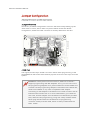
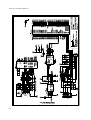
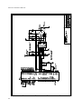
The block diagram shows the main components.
Definitely the most important part is the AT91R40008 microcontroller. It’s a quite
complex chip and described in detail in Atmel’s AT91R40008 data sheet. Almost
all I/O ports are routed to the Ethernut expansion port, a 64-pin connector, which
can be used to add custom hardware like the Medianut MP3 decoder with LCD
interface.
The microcontroller provides two UART channels, which are routed to the onboard RS-232 level shifters.
A Xilinx CPLD is used to implement the glue logic.
While Ethernut’s software offers serveral bootloader capabilities over RS-232 or
Ethernet, program code is initially uploaded through the JTAG interface. The
connector layout conforms to Atmel’s 10-pin AVR JTAG interface.
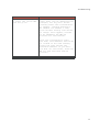
a
WARNING: Ethernut 3 uses the same JTAG connector layout as its
predecessors Ethernut 1 and 2, which is not compatible with the
standard ARM 14-pin or 20-pin connectors. A cable adapter will be
required to attach standard ARM JTAG adapters.
2