1
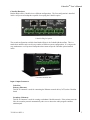
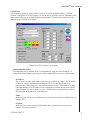
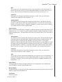
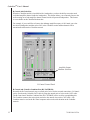
CobraNetTM User’s Manual
CobraNetTM User’s Manual
19201 Cook Street, Foothill Ranch, CA 92610-3501 USA
Phone: (949) 588-9997 Fax: (949) 588-9514
Email: [email protected]
Web: www.renkus-heinz.com
CobraNetTM is a registered trademark of Peak Audio, Broomfield, Colorado
722-RH 419 REV A
1
CobraNetTM User’s Manual
Table of Contents
2
Safety Instructions
3
Introduction
4
What is CobraNet
4
System Design
4
CobraNet Hardware
5
Input/Output Connections
5
Unit Identification
6
Software
7
CNDisco.exe (CobraNet Discovery Program)
7
CobraNet.exe
9
R-Control with CobraNet
12
R-Control and CobraNet Combiner Box
12
722-RH 419 REV A
CobraNetTM User’s Manual
Cautions
Sicherheitsvorschriften
CAUTION
VORSICHT
TO AVOID ELECTRIC SHOCK, DO NOT INSERT
FINGERS OR OBJECTS INTO ANY OPENINGS IN
UM ELEKTRISCHEN SCHLAG ZU VERMEIDEN,
KEINE FINGER ODER GEGENSTÄNDE IN
ÖFFNUNNGEN DES GEHÄUSES STECKENN
WARNING: TO PREVENT FIRE OR ELECTRIC SHOCK, DO NOT
EXPOSE THIS EQUIPMENT TO RAIN OR MOISTURE
WARNUNG: ZUR VERMEIDUNG VON FEUER ODER
ELEKRISCHEN SCHLÄGEN DAS GERÄT NICHT MIT REGEN
Explanation of Graphical Symbols
The lightning flash with arrowhead symbol, within
an equilateral triangle, is intended to alert the use
to the presence of uninsulated "dangerous Voltage" within the product's enclosure that may be
of sufficient magnitude to constitute a risk of electric shock to humans.
Erklärung der graphischen Symbole
Der Blitz mit nach untenzielendem Pfeil in
einem gleichseitigen Dreieck weist den
Benutzer auf das Vorhandensein einer
unisolierten, "gefährlichen Spannung" im
Gehäuse hin, die stark genug sein kann, einer
Person einen gefährlichen elektrischen Schlag
zu versetzen.
The exclamanation point,within an equilateral triangle is intended to alert the users to the presence of important operating and maintenance (servicing) instructions in the literature accompanying
the product.
Das Ausrufezeichen in einem gleichseitigen
Dreieck weist den Benutzer auf wichtige
Betriebs- und Wartungsvorschriften in den
beiliegenden Unterlagen des Gerätes hin.
CAUTION
VORSICHT
RISK OF ELECTRIC SHOCK
DO NOT OPEN
GEFAHR EINES ELEKTRISCHEN
SCHLAGES NICHT ÖFFNEN
CAUTION: TO REDUCE THE RISK OF ELECTRIC SHOCK,
DO NOT REMOVE THE COVER. NO USER-SERVICEABLE
PARTS INSIDE. REFER SERVICING TO QUALIFIED SERVICE
PERSONNEL
VORSICHT! UM DAS RISIKO EINES ELEKTRISCHEN
SCHLAGES ZU VERMINDERN, ABDECKUNG NICHT
ENTFERNEN. KEINE BENUTZER BEDIENUNG-STEILE
IM INNERN. BEDIENUNG NUR DURCH
QUALIFIZIERTES BEDIENUNGSPERSONAL.
CAUTION
VORSICHT
RISK OF ELECTRIC SHOCK:
OPEN ONLY IF QUALIFIED AS
SERVICE PERSONNEL
GEFAHR EINES ELEKTRISCHEN SCHLAGES: NUR
VON QUALIFIZIEREM WARTUNGSPERSONAL ZU
ÖFFNEN
To reiterate the above warnings: servicing instructions are
for use by qualified personnel only. To avoid electric shock, do
not perform any servicing other than that contained in the
Operation Instructions unless you are qualified to do so. Refer all servicing to qualified personnel
Eindrigliche Warnung: Wartungsvorschriften dienen
nur der Benutzung durch qualifizieres Personal. Zur
Vermeidung eines elektrischen Schlages keine anderen
als die in den Betriebsvorschriften beschriebenen
Wartungsarbeiten ausführen, es sei denn Sie sind dafür
qualifiziert. Wartungsarbeiten sind nur von qualifiziertem
Wartungspersonal auszuführen.
722-RH 419 REV A
3
CobraNetTM User’s Manual
Introduction
Thank you for purchasing a Renkus-Heinz CobraNet enabled system. This manual will provide you
with a brief overview of what CobraNet is and how to use it. It will also cover the CobraNet
hardware and its connections. In the software section of the manual, the programs required for
setting up and configuring the system will be covered in detail.
If more detailed information is required on CobraNet, please refer to Peak Audio’s web site located
at www.peakaudio.com.
What is CobraNet?
CobraNet is a real time digital audio distribution system over an Ethernet network. It provides the
user the ability to distribute multiple channels of high quality digital audio over a single CAT5 cable.
Because of the use of CAT5 cabling, installation costs can be greatly reduced.
System Design
The basic components required for a CobraNet system are shown in the block diagram below.
CobraNet requires a device to convert the analog audio signal to a digital signal, which then gets
inserted onto the Ethernet network. This is shown as the Input Box in the block diagram. The
Ethernet network next gets routed through an Ethernet switch. The CobraNet audio is received and
decoded by a device designed to take the signal off the Ethernet network. An example of such a
device would be a Renkus-Heinz self-powered loudspeaker with the CobraNet option or the
CobraNet Breakout Box. The last required item is a computer for monitoring and controlling the
network. The computer is only required for system installation and troubleshooting, not for day-today operation of the system.
CobraNet System Example
4
722-RH 419 REV A
CobraNetTM User’s Manual
CobraNet Hardware
Renkus-Heinz offers CobraNet in two different configurations. The first configuration is installed
inside a self-powered loudspeaker capable of accepting the CobraNet option.
CobraNet Plug-In Option
The second configuration available from Renkus-Heinz is the CobraNet Breakout Box. This is a
stand-alone unit that can be used in any number of different system configurations. It’s compact for
easy attachment to a self-powered loudspeaker that cannot accept the CobraNet option installed
inside.
CobraNet Breakout Box
Input / Output Connectors
CobraNet:
Primary (Ethernet):
This RJ-45 connector is used for connecting the Ethernet network cable (CAT5) to the CobraNet
board.
Secondary (Ethernet):
This RJ-45 connector is used for creating a redundant CobraNet network. If the primary network
fails, the secondary network automatically takes over to insure the audio program continues
uninterrupted.
722-RH 419 REV A
5
CobraNetTM User’s Manual
Input / Output Connectors (Cont.)
Inputs:
Line In:
This is a balanced analog input that is used for bypassing the CobraNet system and inserting an
analog audio signal directly into the self-powered loudspeaker. If CobraNet is functioning, this
signal will be summed with the CobraNet signal being received on Ch 1. In the CobraNet
Breakout Box, this connector has no function.
CNet (CobraNet):
This is a balanced analog input used for inserting an audio signal onto the CobraNet network.
This can be used for sending a signal from the location of the loudspeaker or breakout box to
another location in the facility.
Outputs:
Ch 1 through Ch 6:
These are balanced analog audio outputs from the CobraNet network. Their purpose is to
eliminate the need for more than one CobraNet network module or Breakout Box in all but the
largest clusters and systems. The Ch 1 output is the same signal that is routed internally to the
self-powered loudspeaker.
Indicators:
CobraNet (Ethernet) RJ-45 LEDs:
On each of the RJ-45 Ethernet connectors are two LEDs. If the Primary connector is being
used, then the LEDs on this connector will show activity. The same is true for the secondary
connector.
The left LED on the RJ-45 will either be green or red. This LED should be flashing green
indicating it has found a link and is currently active. If it goes red, a fault has occurred.
The right LED on the RJ-45 will either be green or yellow. Green indicates the unit is powered
up. Yellow indicates the unit has power and this particular unit has been assigned as the
conductor for the CobraNet network.
Sig (Signal Present) LED:
This is the signal present LED. It will indicate when the Ch 1 output has audio present.
Unit Identification
In order for the CobraNet units to communicate on the Ethernet network, a unique address must be
supplied to each device.
Mac Address
Each CobraNet unit has a unique MAC Address. This MAC address number is affixed to each
CobraNet product with either a sticker or a tag. The MAC Address number, for example, should
look something like 0062b02319e. It is important to save this number because it will help aid in
identifying a particular CobraNet unit during set-up and configuration.
6
722-RH 419 REV A
CobraNetTM User’s Manual
IP Address
The IP address is the address used by the CobraNet devices and computers to communicate over
the Ethernet network. In order for the devices to properly communicate, all the devices must
have a unique IP address and be on the same IP network. Refer to the CNDisco (CobraNet
Discovery) program instructions that follow for more information on setting the IP address.
Software
There are two main software programs needed for the installation and configuration of the CobraNet
system. These are the CobraNet Discovery program and the CobraNet program. These programs are
outlined next.
CNDisco.exe (CobraNet Discovery)
Peak Audio developed the CobraNet Discovery program for monitoring CobraNet networks. This
program searches for all the CobraNet devices connected to the network. It’s also used for setting
the IP addresses and updating a device’s firmware.
IP address assignment:
The CobraNet Discovery program will automatically assign the IP address to the CobraNet
devices. By allowing the CobraNet Discovery program to automatically assign the IP address,
you will be assured that there will not be any conflicts between two CobraNet devices having the
same IP address.
To set up the automatic IP address assignment, use the following procedure.
1. Open the CobraNet Discovery program
2. Under the View menu, select Options.
3. In the IP Address Range box, uncheck the Enable Auto Assignment check box.
4. Set the Start IP address for the desired IP address range. For example: 192.168.1.1.
5. Set the End IP address for the desired IP address range. For example: 192.168.1.255
6. Check the Enable Auto Assignment check box.
Once the automatic IP address assignment has been configured, any devices added to the
network will be assigned a unique IP address in the range specified.
Updating firmware:
If it is required to update the firmware to the CobraNet unit, this is accomplished by using the
CobraNet Discovery program. To update the firmware, use the following procedure.
1. Under the View menu, select Options. The Configuration window will appear.
2. In the Database Location box, you need to set the path to the location of the new
firmware. You can either type in the path or use the Browser button. The file you are
looking for is called database.ini.
3. Select OK to close the Configuration window.
4. In the main CobraNet Discovery window, select the CobraNet device on which you wish
to upgrade the firmware.
5. Under the CobraNet menu, select Update Firmware.
6. The Select Firmware Version screen will appear. Select the desired firmware and push
the Update button.
7. It will then ask if you are sure if you want to update the firmware, select OK. Once the
update has been completed, you may need to reboot the CobraNet board.
722-RH 419 REV A
7
CobraNetTM User’s Manual
CNDisco.exe (CobraNet Discovery) (Cont.)
Main Window:
The main window of the CobraNet Discovery program will display all the CobraNet devices
located on the CobraNet network. Here you will see the MAC address and the IP address that
has been assigned to each device. By using this window, you will now be able to see the IP
address for any individual device. You will use this address in the CobraNet.exe program for
setting up audio channel selection.
Main Screen for the CNDisco.exe Program
8
722-RH 419 REV A
CobraNetTM User’s Manual
CobraNet.exe
This program developed by Renkus-Heinz is used for the control of Renkus-Heinz’s CobraNet
products. Through the use of this program, you will be able to select the receivers, transmitters, and
audio channel selections for the Renkus-Heinz CobraNet units. The following section covers the
operation of the CobraNet.exe program.
Main Screen for CobraNet.exe Program
Unit Information Section
The controlling of the CobraNet device is accomplished by using the unit’s IP address. To
determine the unit’s IP address, please refer to the CobraNet Discovery section of this manual.
IP Address:
This is where you enter the IP address of the unit you would like to control. The IP Address
number, for example, should look something like 192.168.1.100. The IP address of a
particular unit, could change for a particular unit from day to day. If the network has other
equipment added to it, the IP address will be reassigned to avoid having two units with the
same IP address. It’s best to always view the CobraNet Discovery program first in order to
obtain the current IP address for a particular unit.
Name:
In this field you can enter in a custom name for a unit in order to aid in its identification. For
example, ST7.
Location:
In this field, text can be entered to help identify where a particular unit is located. For
example, Left Cluster Position 1.
722-RH 419 REV A
9
CobraNetTM User’s Manual
Rx/Tx Selection
Inside the CobraNet unit, there are four receivers and four transmitters. These receivers (Rx) and
transmitters (Tx) are used for either receiving or transmitting the Ethernet bundles down the
network. In the Rx/Tx Selection area of the program, you specify which bundles you want to
receive and on which bundles you want to transmit. The definitions of the bundle numbers are as
follows:
0:
1 thru 255:
256 thru 65,279:
Disables the receiver or transmitter
Multicast Mode
Unicast Mode
Multicast mode: In this mode, many receivers are allowed to access the same bundle number.
Unicast mode:
bundle.
In this mode, only one receiver on the network is allowed to receive the
To enter in a bundle number for ether the receiver or transmitter, select the box for a particular
receiver or transmitter and enter in the desired bundle number. Click the Apply button and the
change will be made.
After entering your desired bundle number for the receiver, the background color of the box will
change. If the background color of the Rx box is green, that receiver has been given permission
to receive on that bundle number and there is a transmitter on the network transmitting on that
bundle number. If the background color is yellow, this can mean either you have not been given
permission to receive on that bundle number, such as in the case of a unicast bundle, or there is
no transmitter transmitting on that bundle number.
For the transmitter, after entering your desired bundle number, the background color of the box
will change. If the background color of the Tx box is green, that transmitter has been given
permission to transmit on that bundle number. If the background color is red, permission has
been denied and you will not be transmitting on that bundle. This usually means that there is
another transmitter on the network already using that particular bundle number.
Latency Selection
The CobraNet system uses a fixed amount of delay (latency) throughout the system. The
standard CobraNet system uses a delay of 5 1/3msec. If less delay is required, you have the
ability to select a lower latency setting. Selecting lower latency settings will reduce the channel
count. For example, at 1 1/3ms latency, the channel count is reduced from 64 to 32 channels.
All the devices on the network must be set to the same latency setting.
Care must be taken to insure the entire network, including the Ethernet switches, can operate
properly at the reduced latency amount. Please refer to the CobraCad program developed by
Peak Audio to insure the network can function properly at the lower latency settings.
Output Selection
Each CobraNet unit has the ability to receive 32 different channels of audio (4 receivers with 8
channels each = 32). Of these 32 possible channels, the unit is capable of outputting 6 of these
channels simultaneously. The Output Selection section of the software allows you to select these
six channels.
10
722-RH 419 REV A
CobraNetTM User’s Manual
RX#:
This is where you select the particular receiver you would like to use for each channel. In
the RX/TX Selection section, you selected the bundle number you wanted each receiver to
receive. Here you select one of the four available receivers to use (receivers 1 – 4).
Channel #:
Each bundle can carry up to eight different channels of audio. Here you select which
channel on the bundle you desire (channels 1 – 8).
Analog Outputs:
This indicates where the analog audio channels are being routed. The Spk/Ch1 (Speaker /
Channel 1) path routs the audio to the speaker internally as well as the Ch 1 output via the
Phoenix style output connector. Channels 2 through 6 are routed to their respective Phoenix
style output connectors on the CobraNet board.
Input Selection
Each CobraNet unit has the ability to transmit 32 different channels of audio (4 transmitters with
8 channels each = 32). Of these 32 possible channels, the unit is capable of outputting 2 of these
channels simultaneously. The Input Selection section of the software allows you to select these 2
channels.
Analog Inputs:
This indicates where the analog audio channels are coming from. The Speaker Monitor path
routs audio from the individual speaker amplifier outputs onto the CobraNet network. By
using R-Control in conjunction with CobraNet, you have the ability to select which
amplifier’s output is routed down the network. This function gives you the ability to listen to
the output of any individual amplifier at another location in the facility. Without R-Control,
the default amplifier is Channel 1. See the R-Control with CobraNet section of this manual
that follow on the next page. This feature does not apply to the CobraNet Breakout Box.
Channel #:
Each bundle can carry up to eight different channels of audio. Here you select which
channel on the bundle you desire (channels 1 – 8).
TX#:
This is where you select the particular transmitter you would like to use for each channel. In
the RX/TX Selection section, you selected the bundle number on which you wanted each
transmitter to transmit. Here you select which one of the four available transmitters to use
(transmitters 1 – 4).
Apply Button
The Apply button will send any changes made to the unit configuration to the CobraNet unit
whose IP address is entered in the IP Address box.
Refresh Button
The Refresh button will go and read all the configuration parameters from the unit with whose IP
address is entered in the IP Address box.
Exit Button
Exits the program.
722-RH 419 REV A
11
CobraNetTM User’s Manual
R-Control with CobraNet:
When the CobraNet module is installed inside a loudspeaker, you have the ability to monitor each
individual amplifier channel inside the loudspeaker. This feature allows you to remotely listen to the
audio coming out of each amplifier channel located inside self-powered loudspeakers. This feature
is not available on the CobraNet Breakout box.
For example, if you would like to listen to the midrange amplifier output, via R-Control you select
the desired loudspeaker and then select Ch 2 in the CobraNet section and that channel will be
transmitted back down the CobraNet network.
Amplifer Output
Montitor Selection
R-Control Control Panel
R-Control and CobraNet Combiner Box (RC-CAT5BOX):
Normally the R-Control network uses a twisted pair of wires for the network connections. R-Control
can be sent down the CobraNet CAT5 cable by using the unused pairs of wires on the CAT5 cable.
The R-Control and CobraNet Combiner Box (RC-CAT5BOX) can be used for accomplishing this.
The Combiner connects the twisted pair network to the unused wires on the CAT5 cable. One
Combiner must be used at the R-Control computer and at each switch location on the CobraNet
network.
12
722-RH 419 REV A


![[SPT-3000] e](http://vs1.manualzilla.com/store/data/005667089_1-a5f3766b3193f6552f250995926a69c5-150x150.png)