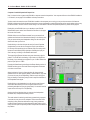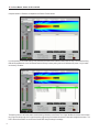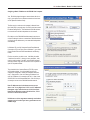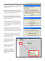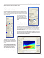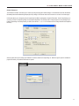
1
Digitally Steerable Line Array Loudspeaker Systems
IC Live
ICL-R & IC215S-R
USERS MANUAL
Version 1.8.0
IC Live Users Manual - Models ICL-R & IC215S-R
IMPORTANT SAFETY INSTRUCTIONS
1. Read these instructions.
2. Keep these instructions.
3. Heed all warnings.
4. Follow all instructions
5. Do not use this apparatus near water. The apparatus shall
not be exposed to dripping or splashing and no objects filled with
liquids, such as vases, shall be placed on it.
6. Clean only with dry cloth.
7. Do not block any ventilation openings. Install in accordance with
the manufacturer’s instructions.
8. Do not install near any heat sources such as radiators, heat
registers, stoves, or other apparatus (including amplifiers) that
produce heat.
9. Do not defeat the safety purpose of the polarized or groundingtype plug. A polarized plug has two blades with one wider than the
other. A grounding type plug has two blades and a third grounding
prong. The wide blade or the third prong is provided for your safety.
If the provided plug does not fit into your outlet, consult an electrician for replacement of the obsolete outlet.
10. Protect the power cord from being walked on or pinched
particularly at plugs, convenience receptacles, and the point where
they exit from the apparatus.
11. Make sure the power cord remains readily accessible at all
times.
12. The AC Power Cord is the AC Mains disconnect.
13. Only use attachments/accessories specified by the manufacturer.
14. Unplug this apparatus during lightning storms or when unused
for long periods of time or during transportation..
15. Refer all servicing to qualified service personnel. Servicing is
required when the apparatus has been damaged in any way, such
as power-supply cord or plug is damaged, liquid has been spilled
or objects have fallen into the apparatus, the apparatus has been
exposed to rain or moisture, does not operate normally, or has been
dropped.
“WARNING - TO REDUCE THE RISK OF FIRE OR ELECTRIC
SHOCK, DO NOT EXPOSE THIS APPARATUS TO RAIN OR
MOISTURE”
“CAUTION: THESE SERVICING INSTRUCTIONS ARE FOR USE
BY QUALIFIED SERVICE PERSONNEL ONLY. TO REDUCE THE
RISK OF ELECTRIC SHOCK DO NOT PERFORM ANY SERVICING OTHER THAN THAT CONTAINED IN THE OPERATING
INSTRUCTIONS UNLESS YOU ARE QUALIFIED TO DO SO”.
Explanation of Graphical Symbols
Erklärung der graphischen Symbole
The lightning flash with arrowhead symbol,
within an equilateral triangle, is intended to
alert the use to the presence of uninsulated
"Dangerous Voltage" within the product's enclosure that may be of sufficient magnitude
to constitute a risk of electric shock to humans.
Der Blitz mit nach untenzielendem Pfeil in
einem gleichseitigen Dreieck weist den
Benutzer auf das Vorhandensein einer
unisolierten, "gefährlichen Spannung" im
Gehäuse hin, die stark genug sein kann, einer
Person einen gefährlichen elektrischen Schlag
zu versetzen.
The exclamanation point, within an equilateral
presence of important operating and maintenance (servicing) instructions in the literature
accompanying the product.
Das Ausrufezeichen in einem gleichseitigen
Dreieck weist den Benutzer auf wichtige
Betriebs- und Wartungsvorschriften in den
beiliegenden Unterlagen des Gerätes hin.
CAUTION
VORSICHT
RISK OF ELECTRONIC SHOCK:
OPEN ONLY IF QUALIFIED AS
SERVICE PERSONNEL
GEFAHR EINES ELEKTRISCHEN SCHLAGES:
NUR VON QUALIFIZIEREM WARTUNGSPERSONAL
ZU ÖFFNEN
To reiterate the above warnings: servicing instructions are for
use by qualified personnel only. To avoid electric shock, do
not perform any servicing other than that contained in the Operation Instructions unless you are qualified to do so. Refer all
servicing to qualified personnel.
Eindrigliche Warnung: Wartungsvorschriften dienen nur der
Benutzung durch qualifizieres Personal. Zur Vermeidung eines
elektrischen Schlages keine anderen als die in den Betriebsvorschriften beschriebenen Wartungsarbeiten ausführen, es sei denn
Sie sind dafür qualifiziert. Wartungsarbeiten auszuführen.
IMPORTANT
2
Your Iconyx Steerable Column Loudspeaker contains no user-serviceable
parts and all service should be referred to qualified service personnel.
IC Live Users Manual - Models ICL-R & IC215S-R
TABLE OF CONTENTS
Section 1: Basic Operating Instructions
Page
Introduction, Technical Support, General Information 4
Setup & Assembly Instructions5
Common Setups
5
Assembly6
Master / Slave Settings
7
Wiring Diagrams8
Basic Setups - No PC Control
8
With PC Control9
Array Input / Power Connections10
Operation (with no PC)11
Presets11
Operation (Computer Controlled) 14
Assigning Digital & Analog Inputs16
DSP Control
17
Panel Controls19
SysTune Interface
19
`
Section 2: Additional User Information
Initial Setup22
Computer Requirements22
Installing RHAON
22
Assigning a Static IP Address
23
Network Manager
24
Virtual Systems25
Linking Software With Networked Loudspeakers
26
CobraNet Signal Routing
28
Beam Steering30
All Loudspeakers / Group Controls39
Copy Settings / Copy Presets 41
Reset 41
Supervise Mode42
Event Logging & Notification
44
General Preferences45
Password Protection
46
Keeping Your RHAON Program Up-To-Date
48
Software Updates
49
Updating Microcontroller Firmware50
Updating DSP Firmware
52
Servicing / Trouble Shooting Hints54
Network Manager
57
Dimensions & Technical Specifications
IC L-R Array65
IC215S-R Subwoofer
67
Index69
3
IC Live Users Manual - Models ICL-R & IC215S-R
INTRODUCTION
Congratulations on your purchase of a Renkus-Heinz RHAON empowered, digitally steered IC Live column loudspeaker. We hope you
enjoy it.
Your IC Live digitally steerable column loudspeaker was carefully tested and inspected before leaving our factory and should have arrived
in perfect condition. Please carefully inspect the shipping carton(s) and loudspeaker(s) for any noticeable damage, and if any damage is
found, immediately notify the shipping company. Only you, the consignee, may institute a claim with the carrier for any damage incurred
during shipping. Be sure to save the carton(s) and all packing material for the carrier’s inspection. It is also a good idea to save the carton
and packing material even though the loudspeaker arrived in good condition. If you should ever need to ship the loudspeaker, it should be
shipped in its original factory packaging.
TECHNICAL SUPPORT
If you have any questions about RHAON-Empowered Loudspeakers or encounter a problem designing, installing, setting up or operating a RHAON system, please call our technical support staff at 949-588-9997 and ask the operator for technical support on RHAON. Call
Monday through Friday from 8:00 AM to 5:00 PM Pacific Time.
The latest information on RHAON Technical Support is always available online at http://www.renkus-heinz.com/support/software-support/
rhaon/e-mail.html. You will also find a support request form at http://www.renkus-heinz.com/support/request-info/tech-info/i
General Information
IC Live line array systems were developed specifically for live event productions. They are ideally suited for a wide range of event types
and sizes, are easy to transport and setup, and deliver superior sound in a broad spectrum of environments.
Thanks to digitally controlled beam steering they deliver narrow vertical beams of sonic energy that can be directed onto the audience
instead of reverberating off the walls and ceilings. Horizontal coverage is a consistent 150o eliminating the need for left and right setups in
most venues. Preset configurations for different size and shape venues reduce setup time to a minimum.
This guide was written to assist you in setting up and operating IC Live systems.
4
IC Live Users Manual - Models ICL-R & IC215S-R
Common Setups
ICL-R digitally steered line arrays and IC215S-R subwoofers
were designed to work together, both acoustically and mechanically with the subwoofer supplying both the extra bass impact
needed by most musical productions and a solid mounting base
for the tall slender columns. Together, the two building blocks
form 6 useful configurations.
The unique interlocking hardware system with Quik-Release pins
joins the line array and the subwoofer together into a rigid assembly, allowing the subwoofers to be used as mounting bases
for the columns. When used as a mounting base, the subwoofers also raise the line array above the floor.
ICL-R arrays perform best when their acoustic center, the point
of origination for the narrow acoustic beam, is several feet above
the ear level of the audience. If it’s placed lower, too much of
the sonic beam is absorbed by the first row of the audience and
never reaches those in the rear. If it’s placed much higher, the
narrow vertical beam tends to” light up” the center of the audience and drop off in both the front and rear.
This puts the ideal height for the bottom of an ICL-R array at
roughly four feet above the floor for a seated audience.
An IC215S-R standing on end is 4’ tall making the combination of an ICL-R array mounted on top of a standing IC215S-R
subwoofer an ideal arrangement for many setups.
An IC215S-R subwoofer laid on its side and a single ICL-R array
work well when space is available for them on the stage. Mounting two stacked arrays on a single subwoofer is not recommended, as the assembly is unstable.
Dual subwoofer assemblies combined with either a single ICL-R
array or with two stacked ICL-R arrays are two other popular
configurations. The dual subwoofers provide the desired mounting height for the array(s) and enough bass for even the most
demanding musical events.
Stacked ICL-R arrays provide tighter beam control than a single
ICL-R and a much higher output level. They are especially
desirable in reverberant rooms where tight control of the beam is
needed to deliver clear speech over a considerable distance.
When only speech is involved and the bass support provided by
the subwoofers is not needed, single or stacked ICL-R arrays
are an ideal solution. They can be attached to the truss work with
Chesebrough clamps or by removing the array’s rear pole/handle
and using the pole clamps to secure the array to the truss.
ICL-R arrays are also equipped with AeroQuip Fly-Track, so they
can also be easily flown from the truss with industry standard
AeroQuip hardware.
5
IC Live Users Manual - Models ICL-R & IC215S-R
Assembly
IC Live is a building block system designed for easy transportation,
setup and tear down. It provides for 6 system configurations from two
basic modules, the ICL-R array module and the IC215S-R subwoofer.
Setup couldn’t be easier. To create a stacked array from two ICL-R
modules:
1. Stand the two column arrays side by side and remove the two joining bars and their short Quik-Release pins from the modules.
2. Place one of the modules on top of the other one. Note that the top
module should be turned upside down so the horn sections of the two
modules are together.
3. Align the two modules and then remove the quick release pin from
the upper module’s rear cylinder to allow its inner sleeve to drop
down into the lower module’s rear cylinder.
4. Then re-insert the quick release pin into the upper module’s cylinder to lock the inner sleeve in place.
6
IC Live Users Manual - Models ICL-R & IC215S-R
Assembly (continued)
5. Slide the two joining bars
into the channels as shown.
6. Lock the joining bars into place
with the short quick release pins to
complete the physical assembly.
Note: If you are assembling a “triple stack”, follow the same procedure to place the third module on top of the second module with one
exception. The woofer sections of the second and third modules should be joined together. If in doubt, refer to page 65 for proper module
orientation.
The procedure for mounting an ICL-R array onto an IC215S-R subwoofer is the same. The only difference is the array’s rear cylinder
sleeve drops into the socket on either the top or the end of the subwoofer. When mounting a stack (two ICL-R arrays) on top of one or two
subwoofers, it is best to first mount the lower line array module onto the subwoofer and then attach the top line array. It’s easier and safer.
Do not attempt to mount a stacked ICL-R array onto a subwoofer standing vertically. The resulting assembly is unstable.
Master / Slave Settings
The next step is to electrically link the modules together and verify
the Master/Slave assignment is correct The bottom module always
functions as the Master and the upper modules as Slaves. The
module directly above the Master module is identified as Slave 1 and
the module above it as Slave 2. .All incoming signal and AC power
connections should be made to the Master module.
Plug one end of the short CAT5 linking cable into the lower interconnect socket on the Master (lower) module and the other end into the
upper socket on the upper module. Then plug one end of the short
AC power cable into the looping power socket on the lower module
and the other end into the power socket on the upper module. Follow
the same procedure to connect a third module, if one is provided.
The next step is to set the two dip switches that identify each module.
Set the Master switches first; The graphic directly below the two
dip switches shows the proper setting for a Master module (both
switches in the down position).
Then set the Slave module(s) dip switches following the settings
shown in the graphic. Note that the Slave #3 switch is for possible
future use.
Note: If you connected power to the array before setting the dip
switches, you will need to turn it off or disconnect it at the source and
then reconnect it before the dip switch settings will take effect. When
properly set the digital readouts will both read 20 in a dual array and
30 in a three module array.
Master
setting
Slave #1 Slave #2 Slave #3
setting
setting
setting
7
IC Live Users Manual - Models ICL-R & IC215S-R
Wiring Diagrams For Basic Setups
IC Live arrays were developed for a wide range of different size and types of venues, including even large multi-array events. They include
RHAON, the Renkus-Heinz Audio Operations Network, which provides operational control and supervision of multiple arrays from a
remotely located computer and multi-channel digital audio distribution.
When remote computer supervision and control is not needed, IC Live arrays can be treated just like any other self-powered loudspeaker.
Simply connect an analog audio signal, plug in the power, make sure the correct Preset is selected and adjust the level. See drawings
below.
Single
ICL-R Array Setup
Stacked (Dual)
ICL-R Array Setup
Stacked (Dual)
ICL-R Array
&
Dual IC215S-R Subwoofer
Setup
8
IC Live Users Manual - Models ICL-R & IC215S-R
System Wiring With PC Control
Notice that no Ethernet switch is needed in single array setups. Instead, only a simple Ethernet Crossover cable is required.
An Ethernet switch is needed only when there are two or more devices, such as an array and a subwoofer. A stacked array is treated as a
single device since it performs as one even though it has two modules.
Satisfactory 100 BaseT Ethernet switches of many sizes (output ports) are available from a number of sources. Unmanaged switches are
adequate for most applications. Managed switches are not required.
Systems using CobraNet digital audio distribution require either a suitable analog to CobraNet converter or a mixing console with a CobraNet output. Suitable analog to CobraNet converters are available from a number of sources, such as Bi-Amp, Peavey and others. The
converter’s output would plug into one of the Ethernet switch ports.
Single
ICL-R Array Setup
with Computer Control
Stacked (Dual)
ICL-R Array Setup
With Computer Control
Stacked (Dual) ICL-R Array
&
Dual IC215S-R Subwoofer Setup
with Computer Control
9
IC Live Users Manual - Models ICL-R & IC215S-R
Array Connections
The ICL-R array and IC215S-R Subwoofer Input/Control panels are shown below.
Looping AC Power Connector
Analog 1 - AES/EBU Input Connector
90/260 V AC Power Connector
Master/Slave Link Cable Connectors
ICL-R
Control Panel
Master/Slave Setup Switches
Signal Present & Clip
Status Indicators
Looping Analog -AES/EBU Connector
Primary & Secondary Ethernet
Input Connectors
Preset Controls
Operating Controls
AES/EBU Input Selector
IC215S-R
Input / Control Panel
Analog 1 - AES/EBU
Primary Input &
Looping Output
Primary & Secondary Ethernet
Input Connectors
Power On / Off
Analog - AES/EBU
Secondary Input
Mute Controls
Level Controls
AC Power Connector
IC215S-R
Power Control Panel
Notice that on both the ICL-R and IC215S-R the Analog and AES/EBU inputs share common input connectors. The AES/EBU Input Selector switches the amplifier between Analog and AES/EBU input modes.
Important: If you are working with a stacked array and one or two subwoofers, make sure your power source (power strip) is adequate to
handle the power drain. A stacked array will draw up to 13 Amps at 120 Volts and each IC215S-R needs a 15 Amp source.
10
IC Live Users Manual - Models ICL-R & IC215S-R
Operation With No PC
This portion of the Users Guide assumes that all input connections have been made and that you are not using CobraNet digital audio for
the program source. If you are using CobraNet Digital Audio, refer to Pages 29 & 30 for detailed instructions.
Note that if you are working with a stacked array, the Slave module is controlled by the Master module and most of the Slave’s controls will
be inoperative. Your connections need to be made to the lower Master module. You also need to make sure the CAT5 linking signal cable
and the short AC power cable that links the two modules together are in place.
We’ll start with a system that will be run without a computer.
1. Plug in the power cord(s) and turn on AC power to the Array. The ICL-R does not have a power switch. However it can be placed in or
out of Standby with the Volume Up and Volume Down push buttons. To change hold both buttons down for several seconds. The Power
LED will glow when the amplifier is On.
2. Check the preset digital readout display to make sure the correct preset is selected. On single ICL-R arrays:
Preset 10: is factory installed and locked to “Flat” for use in transducer testing and
should not be used during normal operation.
Preset 11: is factory installed and locked for small venues needing only a 50 foot
throw
Preset 12: is factory installed and locked for venues needing a 75 foot throw
Preset 13: is factory installed and locked for venues needing a 100 foot throw
Preset 14: was installed by Quality Assurance during final performance testing at the
factory and was not locked. It may have been deleted and replaced by a
user installed preset
Presets 15,16, 17, 18 & 19 are set aside for user installed presets.
On stacked ICL-R arrays;
Preset 20: is factory installed and locked to “Flat” for use in transducer testing and
should not be used during normal operation.
Preset 21: is factory installed and locked for venues needing a 100 foot throw
Preset 22: is factory installed and locked for venues needing a 125 foot throw
Preset 23: is factory installed and locked for venues needing a 150 foot throw
Preset 24: was installed by Quality Assurance during final performance testing at the
factory and was not locked. It may have been deleted and replaced by a user
installed preset
Presets 25,26, 27, 28 & 29 are set aside for user installed presets.
Note: Graphic displays of the Presets can be viewed on pages 12 & 13.
3. If the right preset isn’t selected, use the Up & Down push buttons to select the desired preset. Then press the Enter button. The display
will flash while the new Preset is being loaded and return to a steady glow when the procedure is complete. If by accident, you select an
empty Preset, the dots following the numbers will flash to show no preset is being loaded (no preset is available).
4. If you will be using an AES/EBU digital signal, make sure the AES/EBU input has been selected. The status LED will be glowing green if
it is selected.
5. Check the setting of the Input Pad. The pad should be inserted if your analog input source has a high output level. When On, a 10 dB
pad is inserted into the input circuit enabling the amplifier to handle input levels of up to + 24 dBu. The yellow LED will glow when the pad
is inserted.
6. Set the amplifier’s output level using the Volume Up & Down push buttons. Notice that when you are using these buttons, the digital
readout will display the level setting in dB. You can also mute the output by pressing the Mute button.
Important: The factory presets do not include any EQ, high or low frequency shelving, delay or compression. These can be
added to the presets using a PC equipped with RHAON. Refer to page 17 for details.
11
IC Live Users Manual - Models ICL-R & IC215S-R
Presets ICL-R
Preset 11
ICL-R with 30 degree opening angle and a -2.27 degree aiming angle; suggested for venues with 50’ deep audience areas.
Preset 12
ICL-R with 25 degree opening angle and a -1.53 degree aiming angle; suggested for venues with 75’ deep audience areas.
Preset 13
ICL-R with 20 degree opening angle and a -1.14 degree aiming angle; suggested for venues with 100’ deep audience areas
12
IC Live Users Manual - Models ICL-R & IC215S-R
Presets (Stacked ICL-Rs)
Preset 21
Stacked ICL-R arrays with a 20 degree opening angle provides better control and higher sound levels in venues with 100’ deep audience
areas than a single ICL-R array.
Preset 22
Stacked ICL-R array with a 15 degree opening angle. Suggested for venues with 125’ deep audience areas.
Preset 23
Stacked ICL-R array with a 10 degree opening angle. Suggested for venues with audience areas more than 125’ deep.
13
IC Live Users Manual - Models ICL-R & IC215S-R
Computer Controlled Operation & Supervision
Now, it’s time to look at a system using RHAON for computer control and supervision. Your computer will have to have RHAON installed on
it. If it doesn’t, turn to page 22 for installation and setup instructions.
You also need to be aware that even if RHAON is installed on the computer you are using, you may not have access to all its features.
RHAON includes several levels of password protection to prevent inadvertent or unauthorized changes of the control settings and you may
be denied access to some or all of the control settings. For more details on RHAON and password protection, please refer to page 46.
Double click on the RHAON icon on your desktop to open RHAON.
When RHAON opens, select Scan Network from the menu in the upper
left corner of the screen.
RHAON will then scan the Ethernet network for any connected loudspeakers and list them in the Network sub-directory in the directory tree.
Use your mouse to drag each loudspeaker listing into the work space
where it will show up as an Icon.
Double clicking on the Icon will open that array’s Connect Properties
window where you can check or change the array’s input selections.
ICL-R arrays have provisions for two Cobranet input, two analog audio
inputs and a serial audio (AES3) digital input. Selecting the input you
want is as easy as clicking on the desired radio button.
The square Signal Present indicators turn green whenever a signal is
present. The 10 dB Pad in the Analog 1 input inserts a 10 dB pad into
the Analog 1 input, allowing input signals of up to + 24 dBu. Without the
pad, the input clips at +12 dBu.
Pressing the Beam Steering tab will open the Beam Steering section of
RHAON and allow you to check what Preset configuration is selected
or to select a new Preset.
Selecting either the Control or Supervise tabs will change the loudspeaker icons in the work space by adding 4 control buttons. They allow
you to turn the array On or Off(Standby), wink the array’s wink light to
help you identify it in multi-array setups, mute its output and tell when it
the loudspeaker loses signal.
Double clicking on the loudspeaker icon will open the array’s Supervision window which allows you to see at a glance how the array is
performing and adjust its input gain (output level). You can also mute its
output and turn the array On or Off (Standby).
Opening the Control window gives you access to the loudspeakers
Parametric EQ, Compressor and Delay controls.
The usual method of monitoring a multi-array system during a program
is to watch the array icons in the workspace. Green status bars mean
everything is fine, yellow bars indicate the array is being overdriven,
red bars indicate a problem has been detected. Double clicking on that
array’s icon will open its supervisory window and provide more details on
the problem.
14
IC Live Users Manual - Models ICL-R & IC215S-R
Single array systems can be monitored either with their icon or by viewing the vertical control pane section in one of their property windows. You may have noticed that the vertical control pane is the same in all three of the Properties windows
A detailed description of the vertical control panel’s features and functions follows.
Listing of the loudspeakers model number.
loudspeaker’s DSP sample rate (either 48
kHz or 96 kHz). See Updating DSP
Firmware on page 52 for more details.
Power button switches the amplifier(s) between On and Standby. (turning AC power
on and off is an entirely manual operation).
Text fields for entering a name for the
loudspeaker and listing its location.
Press Wink with Light button to turn the
loudspeaker’s wink light on and off to aid in
identifying the loudspeaker and its location.
Press Wink with Audio to send a Tone
signal or Pink Noise to the loudspeaker.
Output status indicators for each amplifier.
See Status Indicators below for details.
Input signal level bar graph; “0” indicates
the onset of input clipping. Analog inputs
clip at +12 dBu without the 10 dB input
pad, +24 dBu with the pad.
Volume control slider; adjust by grabbing
slider with mouse or by using up/down
arrows .Settings adjustable from “0” to -50
in 1 dB steps, then to -100 dB in one step;
settings below -8 dB prevent the loudspeaker from reaching full output.
Inv. button inverts the input signal polarity;
glows green when signal is inverted. Use
with caution.
Output bar graph. “0” represents the
maximum uncompressed output level;
positive values indicate how far the signal
is overshooting into limiting; negative
values indicate the amount of headroom
left before the onset of limiting.
Mute button mutes the entire loudspeaker.
Amplifier temperature indicator and
bar graph.
Save button
Press to restart the loudspeakers DSP in
the event of a malfunction.
Status Indicators: The Thermal, Peak and Fail indicators above the output meter provide critical information on the array’s status. The
Peak indicator will flash yellow or red whenever the device’s peak limiter is triggered. It’s normal for the indicator to flash occasionally if
the loudspeaker is being used close to its rated output. Flashing frequently is a sign that the system volume needs to be turned down. The
Thermal indicator will start to flash yellow as the amplifier temperature approaches a preset level and will turn red if the temperature continues to increase as a warning the amplifier is about to be shut down. The Fail indicator glows red when the amplifier has been shut down by
the protective circuitry. Heat related shutdowns will reset automatically after the amplifier cools down to a safe temperature.
As a further protective measure, the amplifier’s gain will gradually be reduced in response to overheating and/or to high an input level.
However, it’s best to manually reduce the input signal level (overall system volume) in response to distress signals.
Power Button: Note that the Power button will not show while operating in the virtual world. It appears only when associated with an
actual array.
15
IC Live Users Manual - Models ICL-R & IC215S-R
Computer Controlled Operation (continued)
Assigning Digital and Analog Inputs
The larger right portion of the Properties windows vary with the operating mode. The Connect window is divided into an upper light grey
Internal DSP Connections section and a darker grey lower CobraNet Routing Assignments section.
The Assign Amplifier Inputs portion of the upper section is where you select which one of the Array’s multiple inputs will be routed to the
Main input and which one will be used for the Priority override circuit. RHAON Empowered loudspeakers have provisions for two CobraNet
digital audio inputs, two analog audio inputs and a serial audio (AES3 format) digital input. Selecting the input is as simple as clicking on
one of the radio buttons.
Notice that the Analog 1 input includes a 10 dB pad. In the On position it inserts a 10 dB pad into the Analog 1 input, allowing input signals
as high as +24 dBu. Without the pad, the analog inputs clip at +12 dBu.
The square Signal Present indicators turn green whenever a signal is present.. You can activate any of the analog and CobraNet digital
inputs in the upper group. If you select either of the AES/EBU inputs in the lower group, all Analog and CobraNet inputs are disabled.
The right hand Assign Cobranet Outputs portion of the upper section lets you use any of the audio inputs or amplifier outputs as an output
to the CobraNet network, except for the AES/EBU inputs. AES/EBU signals are clocked separately from CobraNet and cannot be output to
CobraNet from RHAON.
The lower CobraNet Routing Assignments section is where you select which CobraNet input channel you want to use and set up the output
transmitter.
You can use RHAON to Control and Supervise your system without using digital audio distribution via CobraNet, or you can combine digital
and analog signal distribution for redundant signal path and/or life safety applications. However, if you use AES/EBU serial digital inputs,
all other audio inputs are automatically disabled.
If you will be using CobraNet for digital audio distribution in your RHAON system, additional details on this feature can be found on page
28.
16
IC Live Users Manual - Models ICL-R & IC215S-R
Computer Controlled Operation (continued)
DSP Control
The Control properties window includes controls for an 8-band Parametric EQ complete with High and Low pass filters and shelving filters,
plus controls for a compressor, signal delay and several other user configurable DSP functions.
Opening the Control window allows you to tell at a glance what EQ, if any, has been installed into the array’s DSP and change if if needed.
Remember, the presets installed at the factory include only beam steering information. They do not include EQ, delay or compression.
The filter controls are underneath the frequency chart. To activate a filter, click the button above its white data fields; then either type in
your values, use the up-down arrows or scroll with your mouse to adjust the parameters. At the far left is a high pass filter; its low pass
counterpart is at the far right. These filters have three controls: Cutoff Frequency, Type (Bessel, Butterworth, etc.), and Slope. The pair of
filters to the inside are shelving filters, with controls for corner frequency and boost/cut.
The center section gives you control of 8 fully parametric filters, with controls for center frequency, boost/cut and bandwidth in octaves.
When you activate a filter, its button turns green and it appears on the graph – each filter appears in a different color. A solid white line
shows the overall EQ curve. The Bypass All button at the bottom of this section lets you compare filtered and unfiltered signals quickly.
All filter parameters can be controlled with the scroll wheel on your mouse. Click inside the control field and scroll to set: Gain,
Bandwidth, Frequency, etc.
Below the EQ section in the light grey area, you’ll find controls for the Compressor on the left. The controls – Threshold, Ratio, Attack Time,
Release Time and Soft Knee – are similar to the EQ controls. You can type in values, use the Up/Down buttons, or scroll with your mouse
to find the values you want. Under Signal you will find buttons that set the compressor’s trigger point Above, At or Below the Knee.
When the compressor is operating, the Bypass button is red and the Gain Reduction meter on the right side of this section lights up. To
turn the compressor off or to compare the uncompressed output to the compressed output, click the Bypass button. To the right of the compression Reduction Meter is the Make-Up Gain control. This control can be used to restore RMS levels of the compressed signal to those
expected of the signal pre-compression. It has a range of 0 to +12 dB.
The arrays input module’s DSP has 340 milliseconds of signal delay available, if you are using the 48 kHz sample rate; 170 milliseconds if
you are using 96 kHz. Use either the up-down arrows or the slider control to adjust the delay time.
17
IC Live Users Manual - Models ICL-R & IC215S-R
Computer selection of Presets is accomplished in the Beams / Presets window.
If you are operating in the virtual mode (no array connected) the white Presets field will be blank. When an array is connected, the listing
fields will be populated with a list of the Presets stored in the Array’s memory and a green bar will indicate which preset, if any, is loaded
into the array. See below.
The Steering column in the Preset window contains steering information on the Preset. The C: figure identifies the acoustic center location,
the S; figure the aiming angle, the O: figure the opening angle and the final numbers the amount of attenuation assigned to the beam. The
DSP? column shows whether or not the Preset includes DSP data (EQ settings for example).
18
IC Live Users Manual - Models ICL-R & IC215S-R
Load Preset
The Load Preset control and its associated up/down arrows are used to select and install (load) a specific Preset into the array’s DSP
memory.
If no DSP data is included in the Preset, a dialog box will call the lack of DSP data to your attention and ask if it is OK to proceed.
Answering Yes, will initiate the process, introduce a Loading Status screen and hide the lettering in the Beams / Presets window. The Loading Status window will disappear and the lettering will reappear when the process is complete.
Controls
Most of the buttons at the bottom of the window provide additional control over Presets.
The Panel Controls serve different functions. Clicking on the Panel Display control will turn the Preset digital readout display on the rear of
the array On and Off. The display is often turned off during a performance to prevent the readout’s red glow from being a distraction. The
button will say On in red when the readout is turned On. Note that the digital readout can also be turned On and Off using the Preset Up
and Preset Down push buttons on the array’s control panel. Pressing both of these controls at the same time toggles the readout between
On and Off.
The Panel Buttons control locks all the controls on
the rear of the associated array to prevent inadvertent
changing of the settings or tampering. The padlock
icon will be closed when the controls are locked.
SysTune Interface
If you are using SysTune as your measurement
system during setup and tuning, you can access the
array’s DSP from within SysTune.
This allows you to take a measurement, adjust the
EQ settings and then view the result of the changes in
real time within one program and on one screen - - no
more jumping back and forth between programs and
windows.
19
IC Live Users Manual - Models ICL-R & IC215S-R
20
IC Live Users Manual - Models ICL-R & IC215S-R
Additional User Information
21
IC Live Users Manual - Models ICL-R & IC215S-R
Section 2: Advanced Setup Instructions
Initial Setup
Computer Requirements
You need a Windows PC running RHAON software in order to maximize the performance of RHAON empowered loudspeakers and your
RHAON system. You can use RHAON software during the design stage, for system setup, tuning and commissioning, and for remote control and supervision. You can disconnect the computer from the network after commissioning the system, if you or your client are not using
RHAON’s system supervision capabilities.
RHAON software will run on any PC computer that meets or exceeds the following requirements.
Processor / Speed:
RAM:
Interface:
Operating System:
Associated Software:
Screen Resolution:
Pentium / 800 MHz minimum (faster recommended, especially for large systems)
256 MB minimum (more recommended, especially for large systems)
At least one Network Interface Card (NIC) with a 100 BaseT (100 MB/second) or faster
Ethernet Port; two NICs are needed if the computer will also be used to e-mail alerts
Windows XP, Vista and Windows 7 with either 32-bit or 64-bit processors
NET Framework 3.5 or higher (supplied with RHAON installation CD)
1024 x 768 or higher
Installing RHAON
To install the software insert the RHAON Installation Disk into the computer’s CD drive. The installation program should start automatically.
During the installation you will need to select either the 32-bit or the 64-bit install.
RHAON 1.8.0 is downwards compatible with earlier versions of RHAON Microcontroller and DSP firmware so you do not need to
uninstall a previous version of RHAON before installing program version 1.8.0. However, new program features may not function
in loudspeakers running earlier versions of firmware.
If the installation program does not start automatically, go to your
Start menu. Then select Settings/Control Panel & Add/Remove
Programs. Click on Install to start the installation manually. The
RHAON Setup window will open. Click on Next to proceed to the
next step. Then follow the screen prompts until the installation is
complete.
Notice that the program warns you if your display settings may
cause viewing problems. If you are using “Large Fonts,” we recommend you change to the default 96 DPI setting to avoid possible
viewing problems.
The installation program will install RHAON in a Renkus-Heinz/Rhaon folder on your hard drive. It will not uninstall earlier versions of
RHAON. Use Settings/Control Panel and Add/Remove to uninstall
an earlier version if you want to delete it.
The RHAON Installer puts a RHAON Icon on your desktop. Double
click on it to open the RHAON software program.
The grey background of the opening RHAON can easily be changed to something more useful, such as a block diagram of your system
or a photo of the venue. To change the background, go to the Options pull-down menu and select Background Image/Load Image. Then
browse to the drawing or photo you want to use. Be aware that the photo or drawing you import needs to be of approximately the proper
size and shape before importing.
22
IC Live Users Manual - Models ICL-R & IC215S-R
Assigning a Static IP Address to the RHAON Host Computer
Your RHAON equipped computer communicates with the arrays in your system over an Ethernet network and must have
an NIC (Network Interface Card).
The first step is to make sure the computer’s Network Interface Card (NIC) is properly setup. Your NIC must have a static
IP address assigned to it: This enables the RHAON software
to communicate to all the loudspeakers on the network.
Each device on the RHAON/CobraNet network must have a
unique IP address in order to communicate. RHAON software
can assign the IP addresses to your networked loudspeakers
automatically.
In Windows XP, go to My Computer/Control Panel/Network
Connections. If you are using Vista or Windows 7, go to Start/
Control Panel/all Control Panel Items/Network and Sharing
Center.
Find the connection you wish to use. It will likely be called
“Local Area Connection”, unless you have renamed it. Also,
note the model number of the NIC, as the RHAON software
will require it later. Right click the icon and click “Properties” to
open its Properties window.
Then, double click on Internet Protocol (TCP/IP) to open
its Properties window. You will probably see that your
computer is configured to “Obtain an IP Address Automatically”. Change this to “Use the Following IP Address” and
enter an IP address of, for example 192.168.1.1. Next, insert
255.255.255.0 into the Subnet Mask field. Click OK and you
are ready to connect to the RHAON/CobraNet network.
Note: IP addresses are in the format xxx.xxx.xxx.xxx
where “xxx” is any digit from 0 - 255. Local IP addresses
that appear only to other devices on a LAN (Local Area
Network) are defined as ranges 192.168.xxx.xxx, 172.16.
xxx.xxx to 172 and 10.xxx.xxx.xxx.
!92.168.xxx.xxx is the range most commonly used and we
suggest you use it unless you have a good reason to use
another range.
23
IC Live Users Manual - Models ICL-R & IC215S-R
Before connecting your computer’s to the Ethernet
network, you need to make sure that RHAON has
the correct network settings. Open RHAON, go
to the Options menu and select “Preferences”.
On the General tab, make sure the correct NIC
is selected in the Adapter field. It’s the one you
assigned an IP address to while you were following
the directions on the previous page.
Each device on the RHAON/CobraNet network
must have a unique IP address in order to communicate over the Ethernet network. RHAON software
can assign IP addresses to all these devices, but
before RHAON can do this you need to specify a
range of IP addresses for RHAON to use.
The static address assigned to the computer in
Windows sets the “subnet” you will be using. A
subnet is the first three parts (“octets”) of the IP
address. In the example, the subnet is 192.168.1.
Therefore, all the IP addresses on the network will
be in the form 192.168.1.xxx.
You need to define the range of IP addresses
RHAON will scan. Type two valid IP addresses into the two IP Addressing fields: one for the lower limit of the range and the other for the
upper limit. Since 192.168.1.1 is already in use by the RHAON host computer, the lower limit must be at least 192.168.1.2. The upper limit
can be set as high as 192.168.1.255, but needs to be only high enough to accommodate all the devices on the network. Remember each
device must have its own IP number.
After specifying the range of IP addresses that RHAON will assign to the loudspeakers click OK and connect the computer to the RHAON/
CobraNet Ethernet network, i.e., plug in the CAT5 cable.
The Network Manager
Most Iconyx IC-R and ICL-R / ICL-FR setup and installation problems are “network problems” and not Iconyx or RHAON problems.
Your Iconyx array was factory tested before it left our factory and barring shipping damage should be in perfect operating condition. The
RHAON Network Manager allows you to check the integrity of the Ethernet network before you actually link to the loudspeakers. It is accessed from the File pull down menu and identifies network problems for you before you waste a lot of time checking out the loudspeaker.
In the example shown here the ICL-FR Left obviously has a network communications problem while the CF61 DBL and the VoiceBox are
suspect. For more details on the Network Manager refer to page 57.
24
IC Live Users Manual - Models ICL-R & IC215S-R
Virtual Systems
From time to time you may want to create a virtual system within RHAON to verify that you have selected the right equipment for the venue
and to work out the beam settings before taking the equipment to the site.
To create a virtual system, open RHAON and select Add Virtual Devices. When the Add New Speakers dialog screen opens,
use the directory tree to select and add the Array(s) you want to work with and then click on Done.
The program will then place icons for the Array(s) you have selected into the work space.
Double clicking on one of the array icons will open its Connect properties window.
25
IC Live Users Manual - Models ICL-R & IC215S-R
At this point you can set up the inputs in the Connect window and by moving to the Control window set up the array’s control parameters,
just as you would if you were working with a real array.. The only difference is that any setting changes will be saved to a project file and
not to the array.. These settings can then be loaded into the array at the job site over the Ethernet network.
Linking Software Icons With Networked Arrays
To link the virtual array(s) you created in RHAON to the actual array(s), connect your computer running RHAON software to the network
and click on Scan Network. RHAON will find and identify all the arrays on the network and automatically assign them IP addresses .
RHAON will also identify any other CobraNet devices or RHAON empowered loudspeakers on your network and list them along with the
array(s) under the Network sub-directory in the directory tree.
Drag each individual array listing from the Network sub-directory into the main work space and drop it on the appropriate icon.
26
IC Live Users Manual - Models ICL-R & IC215S-R
Notice that when you dragged the listing onto the icon the listing
in the directory tree moved from the Network sub-directory to the
Speaker sub-directory.
If RHAON can’t find any CobraNet devices on the network, the
prompt shown to the right will appear to let you know that something is wrong and to offer trouble shooting hints. For more detailed
trouble shooting instructions please refer to page 54.
When you link a networked loudspeaker with a software icon,
RHAON interrogates the loudspeaker to make sure the DSP settings stored on your computer are synchronized with those in the
loudspeaker’s onboard memory.
If they are not, RHAON displays a prompt that allows you to
choose which settings to use. To upload settings from your computer to the loudspeaker, click on Overwrite Settings on DSP. To
copy the loudspeaker settings into the project file, click on Read
Settings from the DSP.
If you were linking an existing project on your computer into an
existing network, the dialog box shown to the right will appear and
you will need to decide which settings you want to use, the ones
stored in your project file or the ones present in the loudspeakers.
Continue until all networked loudspeakers are linked to icons
in the main workspace. When an icon is linked to a networked
loudspeaker, the status indicator under its name changes from
Unassigned (Red) to OK (Green).
To confirm that the setup is complete,
return to the directory and place the cursor over the loudspeaker listings in the
directory tree.
As you can see from the pop up screens,
RHAON has assigned IP numbers to
each of the loudspeakers.
Note that you also could go to the Network Manager to check the IP number
assignments. It would provide you with a
complete list of all the devices and their
IP numbers.
27
IC Live Users Manual - Models ICL-R & IC215S-R
CobraNet Signal Routing
CobraNet devices transmit and receive digital audio (48 or 96 kHz, 16, 20 or 24 bit) in bundles of up to 8 channels. The number of channels per bundle can vary, depending on latency and resolution settings. The number of bundles available depends on network bandwidth.
Each CobraNet bundle has a number from the following ranges:
0:
1 thru 255:
256 thru 65,279:
Disables the receiver or transmitter.
Multicast mode (many receivers can access the same bundle).
Unicast mode (allows only one receiver to receive the bundle).
In order for CobraNet devices to communicate, their Tx (Transmit) and Rx (Receive) bundle numbers must match. RHAON software makes
this easy. In some cases the settings of a CobraNet source will have already been established with the source’s own proprietary software
and can be changed only with the manufacture’s software. However, if the manufacturer’s software allows it you can set or reset both
receiver and transmitter bundle settings of any device found on the CobraNet network using RHAON software.
The first step in setting up CobraNet routing is to scan the network and then drag the
CobraNet Source that was detected by Scan
Network into the work space.
The CobraNet Source and the devices connected to it must have the same Sample Rate
and Latency settings. Right clicking on the CobraNet Source Icon will open a pop up screen
showing the Sample Rate and Latency settings.
We suggest you accept the Source’s default
settings unless you have a specific reason to
change them.
You will then want to check the device settings to make sure they are the same as the
Source’s settings. The settings must be the
same for the source and for all devices connected to it.
While latency may be changed here via pointand-click, the sample rate is pre-programmed
in the DSP firmware running in the loudspeaker.
You can switch the sample rate only by uploading the appropriate firmware to the loudspeaker.
Please refer to page 52, “Updating DSP Firmware” for information on how to upload new
firmware to your device.
Next, check the bundle settings of the CobraNet Source device. The Source in our example has 4 Receivers and 4 Transmitters. The
red triangles on the left of its icon represent Rx
bundles and the green triangles represent Tx
bundles. Right clicking on one of the triangles
will open a pop up window that shows the
bundle number and allows you to change it.
28
IC Live Users Manual - Models ICL-R & IC215S-R
The next step is to connect the
CobraNet Transmitters in the
Source to the CobraNet Receivers in the RHAON loudspeakers.
Double click on one of the Source’s
green Tx triangles and then double
click on one of the loudspeaker’s
red Rx triangles to connect the two.
A connection line will let you know
the connection was completed. The
loudspeaker’s Receiver automatically inherits the bundle settings of
the Source Transmitter. Keep
repeating these steps until all the
loudspeakers are connected.
To correct a mistake or change an
assignment, double click on the
Receiver whose assignment you
want to change or right-click on the
Receiver Icon and select Disable
Receiver from the menu that pops
up. Either method will break the
connection and allow you to make a new one.
Since each CobraNet bundle can carry 8 channels of digital audio, you must make channel selections individually.
Once your Tx and Rx bundle assignments have been made, open
each loudspeaker’s Properties
window by double-clicking its icon.
If the window does not open in
Connect mode, click on the Connect
tab at the top to display the window
shown at the right.
In the lower-right section of this
window, you make channel assignments by clicking and dragging to connect audio channels
from the CobraNet source to the
RHAON loudspeaker’s CobraNet
Receivers.
You can also assign Outputs 1 and
2 (selected in the upper section under Assign CobraNet Outputs) to the
RHAON loudspeaker’s CobraNet
Transmitters.
29
IC Live Users Manual - Models ICL-R & IC215S-R
Beam Steering
Iconyx ICL-R digitally steered arrays produce tightly focused, precisely aimed beams of acoustic energy that maintain their intensity well
over long distances. The FIR files that shape and aim these beams of energy are created within RHAON under Beam Steering and then
either stored as a Preset or loaded into the array’s DSP.
Presets are an Iconyx feature that allows you to store up to 10 preset beam steering and DSP control setup configurations in the array’s
DSP memory and then select between them. To enter Beam Steering, open the Beams / Presets Tab and click on Beam Steering.
This will open the Beam Steering window shown below.
30
IC Live Users Manual - Models ICL-R & IC215S-R
The opening Beam Steering window shown on the previous page doesn’t show the array’s beam. Pressing the Calculate Mapping button
and following the prompts tells the program to calculate and display the beam. A typical Map appears below.
Note the four control buttons in the lower right corner of the Beam Steering
window. Pressing Write to Device will send any beam steering configuration
setting changes you have made directly to the array’s DSP and write over any
previous settings.
Pressing Save to Preset will store the configuration settings as a configuration
Preset in the selected preset file. We’ll go into Presets in more detail later.
Note that in both cases, only the beam steering information is being sent to the
Array’s.
Export Setup will generate a .rhs setup file that can easily be imported into an
EASE and EASE JR model for a detailed acoustic evaluation. Beam Steering
shows you the array’s vertical coverage, but not the horizontal coverage or the
effect of reflections on intelligibility and clarity. EASE and EASE JR do.
Import Setup allows you to import into Beam Steering any changes you may have made in the configuration settings in EASE or EASE JR.
31
IC Live Users Manual - Models ICL-R & IC215S-R
Before going on you should first verify
that the correct measurement system is
being used (feet or meters). The default
measurement system is feet but you
may want to use meters.
To check or change the setting, select
Preferences from the Options pull down
menu in the tool bar section of RHAON
or right click in the center of the beam
steering window.
If you want to change from feet to meters, check the Metric radio button.
Note that this window also allows you to
control the behavior of the Fault Relay
and the Power-On sequencing delay.
The Beam Steering tab contains the
setting controls for the appearance of
the Beam Steering window. The normal
default setting are shown.
Notice that this setup window also
allows you to change the height of the
measuring plane (the Ear Height). Until
you are more familiar with the program
we suggest you accept the default setting. There are times, however, when
you will want to change the height of
the measuring plane. It is set to 1.2
meters (3.94 feet) which is fine for a
seated audience, but not for a standing
audience. For a standing audience a
height of 5.5 feet is commonly used.
The Mapping Appearance section
allows you to control the appearance
of the main Mapping plot. For now, we
suggest using the default settings. You
can experiment with various settings
later.
The Scale Level Views section gives
you control over the scales used in the
main Mapping window. Many experienced users like to use the Fixed
Range option under Scale Level Views;
setting the Round Up to 5 and the
Show Range to 5. You may want to experiment with this to see which settings
you like best.
We’ll investigate the other tabs later.
32
IC Live Users Manual - Models ICL-R & IC215S-R
You should know the physical dimensions of the area(s) you want to cover, so the
next logical step is to set up the audience area(s) using the Audience Area section on
the right side of the Beam Steering screen.
To simplify this step, Beam Steering provides five templates, the Standard one used
as the default starting point and four others; Small Arena, Large Arena, Open Air and
Theater. These templates are available by clicking on the Area Presets button. You
should become familiar with these templates, so we suggest you try each one of them
and then choose the one that comes closest to matching your project. Note how the
number of areas and the size of the Audience Areas change from one template to
another.
Once you have selected the template, alter the Audience Area size(s) and location(s)
to match your project’s dimensions. Notice that you can also add or delete up to a
maximum of 3 Audience Areas by using the Number field and associated drop down
arrow.
The Start field establishes the beginning point of the Audience Area relative to the “0”
point of the graph. The Start point is usually the first row of seating. Height 1 is the
height of the front of the Audience Area. It usually is “0” for the front of the first floor
area.
Length is the physical length of the Audience Area from the front edge to the rear
edge. Height 2 is the elevation (height) of the rear of the Audience Area above the “0”
plane.
The next step is to configure the steerable column(s) you will be using in your
project,i.e., to position them, define the beam(s), etc. using the IC Configuration
section on the left side of the window. See graphic to the lower right. The down arrow
associated with the Setup field allows you to select between arrays in multiple array
systems.
Now, it’s time to locate (position) the steerable column. Usually it will be on the front
wall (X = 0.00) in the beam steering Project display. If it will be placed at the front of
the stage away from the front wall, for example, move it forward by inserting its correct location. Note that after you insert a figure in the field, you need to press Enter on
your keyboard to OK the change in location.
The Y field controls the height of the column array by positioning the bottom of the
column above the Floor level (the “0” level) The default position is 6.56 feet (2
meters). The Mechanical Angle field tilts the column forward or backward (minus [-]
numbers tip it back and plus [+] numbers tilt it forward). This parameter is usually left
at 0.0 since the normal position for IC Live arrays is flat against a wall and the array’s
output digitally steered down onto the audience area.
The next step is to choose the number of Beams using the Beams field and its associated drop down menu. One of the unique features of Iconyx steerable arrays is the
ability to generate either single or multiple lobes. We’ll be discussing multiple lobes
later in this tutorial, so for now accept the default 1 beam (single lobe) configuration.
Beam Size lets you choose the Array’s opening angle which controls the sharpness of
the vertical lobe (beam). Try it out using the drop down arrow. Notice how the opening angle of the array in the graphic varies as you choose different opening angles.
The High-Pass at [Hz] control allows you to insert a high pass filter into individual
beams. This new Beamware feature is used to balance the system’s low, mid and
high frequency content to improve intelligibility,
33
IC Live Users Manual - Models ICL-R & IC215S-R
Normalize Beam EQ is a new Beamware feature. Selecting this feature by putting a
check in the check box instructs Beamware to apply a normalized EQ curve to the FIR
filters and reduces the amount of EQ that will be needed during final commissioning.
This feature relies upon the accuracy of the audience area configuration for its calculations, so be sure you have properly defined the audience area and the location of the
array before using it.
Auto-Focus in RHAON v1.8 will analyze your project and suggest the number of beams,
their acoustic center location, their aiming and relative gain - all at the touch of the AutoFocus button. We’ll explore its use later on.
Note that at any point in the setup process you can click on the Calculate Mapping bar
to tell the program to map the array’s performance on the audience area.
As soon as you press Calculate Mapping, a pop up screen will ask you to choose the
resolution of the simulation. Low Resolution simulations are much faster to run than
High Resolution ones. All you need to do to start the simulation is to make your resolution choice by pressing one of the bars.
You also have the opportunity to choose the simulations Bandwidth, its Center Frequency and its Weighting. The Frequency section lets you select center frequencies from
100 to 10,000 Hz. The default selections for the Bandwidth section allows you to run the
simulation over 1 octave or 3 octave bands or Broadband.
You can change this by going to the Options window (F9), selecting the Appearance tab
and checking Show 1/3rd Octave. This adds a 1/3 octave selection to the drop down
Bandwidth menu and the opportunity to set a specific bandwidth for the mapping simulation. In the graphic shown, for example, selecting “to 3150 Hz” would run the simulation
over the frequency range of 1000 too 3150 Hz.
We’ll choose the default settings for this exercise, but you may want to try out all the
different settings to become familiar with them and the performance of steerable arrays.
Beam Angle aims the vertical beam up or down. Try it out by selecting Beam Angle [*],
changing the number and observing its effect.
Note that after entering a new number you will
need to press Enter to initiate the change. You
will also need to do a new Calculate Mapping
to view the change. The old map will have
been wiped out by the program as you made
the change.
You can also check Focal Point [ft] and then
enter the exact location of the beam’s focal
point in Height from Floor and Distance from
Front.
Another way to position the beam’s focal point
is to use the mouse cursor to grab the end
point of the aiming axis and move it to the
desired location.
Try it out. It’s easy to do. The SPL levels in
the graphs will change as the setup parameters change.
34
IC Live Users Manual - Models ICL-R & IC215S-R
Now, let’s investigate the multiple beam capabilities of Iconyx.
In many installations, a single beam is the ideal solution for the room’s acoustical challenges. In some cases, however, multiple beams are needed to provide the desired
coverage. Rooms with a balcony are a good example; in most cases a single beam can’t
cover both the main floor and the balcony.
One solution is two line arrays, one for the floor and the other for the balcony, but this is
expensive. In other cases, architectural considerations or microphone placement dictate
that the column be mounted higher than is ideal and it’s impossible to cover the audience
area with a single beam.
Iconyx solves these problems by
offering multiple beams. To explore
this unique Iconyx feature, click on
the drop down arrow associated with
Beams.
Notice that on a dual or stacked
ICL-R array you can select up to a
maximum of 8 beams. It’s up to four
on a single ICL-R. For now, select 2
to add a second beam to the graphic.
At first glance it may appear that nothing happened since the program may have
placed the second beam on top of the first beam. One way to tell that a second beam
has been added is that the left side of the window now includes a second Beam Parameter section. Refer to graphic to the left. Notice that the second beam is identified
with a dark blue aiming poin
Notice that the second beam also includes a Relative Level field. This allows you to reduce the level of this beam relative to the first beam, a useful feature when the second
beam is covering the front of the audience area.
The High Pass at [Hz] section lets you add
high frequency content to maintain consistent
high to low/mid frequency balance throughout
the room.
Take a few minutes now to become acquainted with the many design possibilities offered
by Iconyx steerable arrays by playing around
with the number of beams, their opening
angles, their aiming and their relative levels.
One of the things you will notice is that as the
number of beams increases, the output level
of the individual beams decreases.
35
IC Live Users Manual - Models ICL-R & IC215S-R
Now that we understand the basics of using beam steering,
it’s time to investigate another one of the unique tools beam
steering includes to make life easier for you. It’s called AutoFocus. You’ll find it in the IC Configuration section next to
Beams.
Clicking on Auto-Focus will open the setup window shown
to the right. Notice that only the Optimize Number of Beams
is checked and that except for the Optimize Gain of Beams
the other selections are not available,. Approve the use of
Auto-Focus by clicking on OK and the program will analyze
your project and suggest the number of beams, their opening
angles, the proper location for their acoustic center (s) and
their aiming.
One word of caution, Auto-Focus can only be as accurate as
your model so make sure your model is correct.
If you had also checked Optimize Gain of Beams, Auto Focus
would have also optimized the gain of each beam to smooth
out the coverage. .
You do not need to accept the programs suggestions. If you
don’t, make whatever changes you feel should be made and
return to Auto-Focus.
Notice that now the Keep existing number of Beams and Max
Coherence functions are available giving you the opportunity
to recalculate based on Max Coherence or on the criteria you
defined (User Defined).
Try it out. Auto Focus can save you time and you need to be
familiar with it.
Auto-Focus will also let you know if the location you have
chosen for the steerable array isn’t ideal. You can override
this warning if you want and the program will still attempt to
properly focus all the beams. You may, however, want to try
moving the array up or down to see if you can find a better
location for the array or use more or fewer beams to see it you
can eliminate this warning prompt.
36
The graphic below shows a 90 foot deep room with a single IC Live array, a typical starting point for a beamware project in a room of this
size.. Note that the single beam opening is set at 20 degrees and the acoustic center placed at 7.
The next graphic is of the same room after Auto-Focus has been applied. Note that Auto-Focus is suggesting 2 beams.
IC Live Users Manual - Models ICL-R & IC215S-R
Map of the setup shown on the previous page..
At this point the beam steering changes have not been sent to an associated array or stored as a Preset.
ICL-R arrays can store up to 10 different configurations as Presets in their DSP memory, but beam steering data and other configuration
settings can not be saved as a preset in the Virtual mode. The configuration settings can be saved in the project file, but they can not
loaded into an array until one is connected.
When an array is connected selecting either Write to Device or Save as Preset in the Beam Steering window will allow you to send the
beam steering information to the array. The two commands are in the lower right of the beam steering window. Write to Device will send
the beam steering settings direct to the array’s DSP and write over any previous settings. Save to Preset will store the beam settings in the
designated Preset.
If you attempt to leave Beam Steering without saving the setup information, a prompt will remind you that you need to save the settings if
you want to keep them.
Note that the Beam Steering module controls only beam steering. EQ, compression, etc. configuration settings are controlled in the Control
Mode.
38
IC Live Users Manual - Models ICL-R & IC215S-R
All Loudspeakers & Group Controls
Add Group
All Loudspeakers Icon
Now it’s time to turn our attention to the All Loudspeakers icon in the upper left of the work space
and to the Group feature of RHAON...
All Loudspeakers controls all the arrays in the
system while Group controls only arrays included in the Group.
All Loudspeakers allows you to Mute all the
arrays simultaneously or to turn them all On or
Off with the push of a single button. You can
also assign Input connections, EQ, Delay and
Compression settings for all the loudspeakers in
the system at one time or adjust their sound level
with just one control.
Group Control functions in the same manner only
it exerts control only over the arrays included in
the Group. To add a Group, select Add Group
to add a Group folder to the directory tree and
a Group icon to the work space. Then drag the
Arrays you want included in the Group from their
listing in the directory tree into the Group folder.
Notice that as you add Arrays to the Group their
icons disappear from the work space into the
Group icon. To view all the array icons within the
group, click on the Expand/Collapse toggle in the
lower right corner of the Group icon. The icons
for the arrays included in the Group are linked to
the Group icon and cannot be individually moved
around the work space.
39
IC Live Users Manual - Models ICL-R & IC215S-R
Double clicking on the Group icon will open
the Connect Properties folder. Notice that the
Group Connect window shown here is very
similar to the one for individual loudspeakers except for the lack of level meters and
CobraNet channel selection facilities.
In the dark grey area on the left are Power,
Wink with Light and Wink with Audio buttons.
These tools are similar to those in a Loudspeaker Properties window, but of course the
Wink buttons “Wink’ the front grille lights of
all the loudspeakers in the Group, or sends
an audio signal (sine wave signal or pink
noise) to all of them.
The Power button puts all amplifiers in the
Group in Standby or turns all of them On.
The Input Volume control and Mute button
also affect all amplifiers in the Group. Group
metering is not available.
The Input selection radio buttons in the light
grey area operate in the same way these
controls operate for individual loudspeakers,
but control all loudspeakers in the Group.
The Control mode windows for All Loudspeakers and loudspeaker Groups is identical
to the one used for individual loudspeakers
except for the lack of level meters and the
addition of a row of Group Assign boxes
under the EQ filters.
When the Group Assign boxes are checked,
Group EQ and dynamics settings override
individual loudspeaker settings – that is, the
settings you define in the Group window will
be uploaded to all loudspeakers in the Group.
Any EQ filters you do not assign to the
Group will be available within each individual
loudspeaker.
Whenever you assign an EQ filter or the Compressor to Group-level control,a Warning prompt
pops up to remind you that you will be overwriting
individual loudspeaker settings.
These controls will be “grayed out” in the individual loudspeaker Properties windows to show that
they are under Group control and unavailable.
All Loudspeakers functions in the same fashion
as Group control, except all of the loudspeakers
are included within the group.
40
IC Live Users Manual - Models ICL-R & IC215S-R
Copy Settings / Copy Presets
Copy Settings / Copy Presets is a useful RHAON feature that can save
you significant time on many projects.
Right clicking on any of the Array Icons while in either the Connect or
Control mode introduces a pop up menu that includes a Copy Settings command line. Selecting Copy Settings copies all that array’s
DSP settings, including Presets and allows you to copy these settings
to another array by selecting its Icon and using Paste Settings.
Right clicking on another loudspeaker and pressing Paste Settings
introduces the window shown below, which allows you to select what
Settings and Presets you want to Paste (copy) into that array.
Note that Copy Presets functions on Presets and Beam Steering only between network connected arrays; it operates only on DSP settings
in the virtual mode. It also functions only between like units. You cannot, for example, copy Presets or beam steering information from an
IC8-R to an IC32-R or from an IC8-R to an ICLive ICL-R. If you try, a warning prompt will alert you to the oversight.
Reset
Reset is a RHAON feature that allows you to restore an array’s DSP and beam steering settings to their original default settings, quickly
and easily. Reset can be initiated from either the controls on the rear of the array or from the associated computer.
On the array’s rear control panel simultaneously pressing the Volume Up and Pad buttons for several seconds initiates Reset even when
the panel controls have been locked. It provides a means of gaining control of the array when a RHAON equipped computer isn’t available.
In RHAON on your computer pressing the Reset button in the RHAON Beam Steering window or pressing Ctrl + Load Preset while in
either the array’s Connect or Control Properties window also enables the Reset feature. A prompt will ask if you want to restore the array’s
default settings. Answering Yes will initiate the change and restore all the default setting. It’s a good way to return to “ground zero” if the
array starts behaving strangely.
41
IC Live Users Manual - Models ICL-R & IC215S-R
Supervise Mode
RHAON’s Supervise mode is the one you will use most while your system is in operation (i.e., making sound). It is designed to empower
system operators with a comprehensive set of monitoring and loudspeaker/amplifier management tools. In Supervise mode, you can
quickly detect a problem anywhere in the system and (if you have access to the appropriate Control mode functions) take corrective action.
To switch from Control Mode to Supervise Mode, click on the Supervise tab in either the main workspace, or in a Group or Loudspeaker
Properties window.
The main Supervise screen is similar to the Connect screen. It shows your system layout in icon form. The Status field at the bottom of
each icon allows you to monitor all Loudspeakers or Groups at a glance. This field will change color and display a text message that indicates the status of the loudspeaker. If there is a problem with any loudspeaker in a Group, that Group’s icon will change color and display a
text alert.
In Supervise Mode, each Status Indicator will display one of the following colors and messages:
COLOR
MESSAGE
STATUS
GREEN
OK
This loudspeaker is (or all loudspeakers in this Group are) connected and operating
YELLOW
Overload
Amplifier is being over driven
RED
Unassigned
Virtual loudspeaker has not been assigned to a physical loudspeaker
RED
Offline
Loudspeaker has lost power or been disconnected from the network
RED
Driver Open
One of the loudspeaker’s drivers has failed
RED
Hot
An amplifier’s over temperature circuitry is engaged
RED
Limiting
An amplifier is being over driven or is malfunctioning
RED
Amp Fail
An amplifier has failed
If a Group icon displays an alert (yellow or red bar with text), double-click it to Expand it and show all of its Loudspeaker icons. One of
more of these icons will display the same alert: double-click it to open that loudspeaker’s Properties window in Supervise mode See below.
42
IC Live Users Manual - Models ICL-R & IC215S-R
The dark grey pane on the left is identical to the pane in Control Mode. It includes the loudspeaker’s input and output monitoring facilities,
identification fields, and basic operating controls: Power On/Standby, the Wink Light toggle, Wink with Audio, Input Gain, Polarity Invert,
and Mute. Any or all of these controls may be restricted to authorized operators and subject to password-protected access.
The loudspeaker icons on the right each have “traffic light” status indicators; Green for all OK and red for driver failure. Yellow indicates
the driver has repeatedly been driven far enough into limiting that its normal life span may have been reduced. The traffic light conditions
are mirrored in the status field of the supervise icons. Driver conditions are dynamically supervised with program material but an additional
test button can confirm coil status. The use of these manual test buttons is required in case the program material either lacks specific
frequencies or is too weak.
Notice that all of the drivers in the array are being monitored and that each module has its own Wink light button. This allow you to easily
identify each module and verify that its address number switches are properly set.
The loudspeaker’s RHAON Microcontroller and DSP Firmware version and MAC (Machine Access Control) address are shown in a darker
grey panel at the bottom right of this window.
The panel at the bottom shows alerts for Voltage Detect, Fault Relay, Ethernet and Priority Override status.
The Priority Override indicator will change from showing “Inactive” to “Active” when the override circuit is in use (has been activated).
The Fault Relay status line will change from “Off” to “On” when an amplifier fault has been detected or the Ethernet carrier signal is lost.
The Voltage Detect will read “High” when it senses a voltage on the Sense input line and “Unknown” when no voltage is present.
The Ethernet Status will show “Primary” when an Ethernet Carrier signal is detected at the Primary Ethernet input and “Off Line” if the carrier signal is lost, except in “Redundant” systems having a secondary Ethernet source. In these systems, the amplifier will be switched over
to the secondary input as soon as the primary signal is lost; the status line will then change to Secondary”.
43
IC Live Users Manual - Models ICL-R & IC215S-R
Event Logging & Notification
RHAON’s Event Logging function can record in a .log file events of the types you select. This allows the system’s operating status to be
reviewed at any time. Audio evacuation and life safety systems are often required to provide this type of logging.
To activate this feature, go to Options in RHAON’s main tool bar and select Preferences; then open the Event Logging folder. Select the
event types you want to log using the check boxes next to each type of event.
Click on OK to activate Event Logging. The log file will be written to the computer’s hard drive in a RHAON.log file in the Program Files/
Renkus-Heinz directory.
RHAON can also automatically e-mail events to another computer or cellular phone. You configure this function in the Event Notification
folder next to Event Logging. As with logging, you can choose the types of events for which you want RHAON to send e-mail notifications.
Because RHAON connects to a NIC (Network Interface Card) with a local IP address, you will need a second NIC in your computer to
connect to the Internet. You will also have to specify the SMTP (Simple Mail Transfer Protocol) host and a valid e-mail account in order for
RHAON to send e-mail. An IT professional may be able to assist you with these tasks if you need help.
44
IC Live Users Manual - Models ICL-R & IC215S-R
General Preferences
The Preferences window also allows you to review and change the program’s default settings. You will find them under the General tab.
We already discussed the Networking Adapter (aka NIC) settings in the Connect section of this manual. so we won’t cover them again.
Unit System allows you to change the units of temperature from Metric (Centigrade) to Imperial (Fahrenheit). Under Group Settings, you
can set up a Power On Sequencing Delay for all grouped loudspeakers. This will help avoid a voltage surge that can trip building circuit
breakers. Depending on the delay interval you select, there will be a .5, 1.0, 1.5 or 2.0 millisecond turn-on delay between each amplifier in
the Group.
Start Up options allow you to always open RHAON in Full Screen mode and to require Sign-In. When the Sign-In option is checked, the
program will ask for your password whenever it is opened.
45
IC Live Users Manual - Models ICL-R & IC215S-R
Password Protection
RHAON software includes three levels of password protection. This features is designed to prevent inadvertent changes of Connect and
Control Mode settings by anyone who is unauthorized or unfamiliar with the system.
To open the Password Protection setup window shown below, hit Control-Alt-p.
You can set up three levels of control access. They are called Designer, Operator and Supervisor. Each access level should have its own
password.
The Designer has the highest level of access. This person should set up the access control system and passwords before turning a
RHAON system over to its owners and operators.
The Operator has the next highest level of access. We suggest giving an Operator access to all Control Mode functions that would normally be used while running a show or operating the system. In a fixed installation, Operator level personnel would probably not be granted
access to the Compressor, EQ, Delay, Shelving and roll off controls, but they would be able to adjust Input Gain if necessary to respond to
clipping and/or over temperature alerts.
The Supervisor access level is intended for those who are only monitoring (supervising) the system for faults and failures. Supervisors
would normally be given access to few, if any, of the functions in Control Mode.
RHAON passwords are case sensitive. Once the password access system has been set up it will be impossible to operate RHAON without
entering a password. The Password Prompt shown below will appear each time the program is opened and a proper password must be
entered before proceeding.
46
IC Live Users Manual - Models ICL-R & IC215S-R
Clicking on the Access Detail tab opens the window shown below. Its settings determine what control features will be available to “Operators” and “Supervisors”. These settings are themselves password protected and can only be changed by a Designer.
The Password restrictions are stored on the computer used to setup the password protection (usually the“House” computer ) and don’t
prevent you or someone else from connecting to the network with a RHAON equipped PC and changing the settings.
The Speaker Protection window provides an additional level of protection, as it allows locking the settings for individual loudspeakers to
positively prevent their being changed by anyone who doesn’t know the password. It locks the settings in the array to prevent anyone who
doesn’t know the passwords from changing the settings
47
IC Live Users Manual - Models ICL-R & IC215S-R
KEEPING YOUR RHAON PROGRAM UP-TO-DATE
Updating Your Current Installation of RHAON
New program versions of RHAON are posted on the Renkus-Heinz website, www.renkus-heinz.com, as soon as they are created. We
recommend updating to the latest version only if the newer version has features that you need, such as an expanded listing of RenkusHeinz loudspeakers. In other words, follow the “if it isn’t broke, don’t try to fix it” policy.
There are two easy ways to find out what version of RHAON is installed on your computer so you can determine if a later version is available. The first is to simply open RHAON and observe the opening splash screen. The program version number is displayed there as the
program is
opening.
The second method is to open RHAON and select the Help drop down menu and click on About RHAON. This will bring up a dialog box
with the current RHAON information
48
IC Live Users Manual - Models ICL-R & IC215S-R
KEEPING YOUR RHAON PROGRAM UP-TO-DATE
Updating Your Current Installation of RHAON (continued)
To update your RHAON program go to www.renkus-heinz.com and click on RHAON in the left hand menu. You’ll see the link to the latest
RHAON program version at the top of the RHAON home page; see below.
Select(Download Latest Program Software) from the top of the RHAON
page and download the RHAON Installer (higher version numbers indicate newer releases).
Click on Run or Save the file to your computer and then double click on
the .exe file to begin the installation routine.
RHAON 1.8.0 is downwards compatible with earlier versions of
RHAON Microcontroller and DSP firmware so you do not need to
uninstall a previous version of RHAON before installing program
v 1.8.0. However, new program features may not function in loudspeakers running earlier versions of firmware.
The installation program installs RHAON in a Renkus-Heinz/Rhaon folder
on your hard drive and overwrites v1.4 or higher versions of RHAON.
If you have an earlier version of RHAON on your computer, you do not have to uninstall it. If you want to remove it, you will need to us
Start/Control Panel and Add/Remove to uninstall it.
Updating Microcontroller and DSP Firmware
The latest Microcontroller and DSP firmware files were installed in your loudspeaker before it was shipped to you. They contain the
program that runs the DSP microcontroller and the loudspeaker specific control files for
the associated loudspeaker. These files are updated from time to time as the firmware is
updated and improved.
If you are having problems with your system, we may ask you to update the firmware as
part of the troubleshooting procedure.
Updating firmware is not as simple a task as updating program software and we
recommend you refrain from updating your firmware unless you have a good reason
for doing so and you have discussed the process with our technical staff.
If you do need to update your firmware, RHAON make it easy for you to do so. Selecting
Check for Firmware from the RHAON Help pull down menu will connect your computer
to the firmware download site, check for new firmware files and download any it finds.
49
IC Live Users Manual - Models ICL-R & IC215S-R
Updating Microcontroller Firmware
The latest Microcontroller firmware files (.hex files) were installed in your loudspeaker before it was shipped to you. These files contain
the programming that runs the DSP microcontroller in RHAON empowered amplifiers and are updated from time to time as the firmware is
improved.
If you are having problems with your system, we may ask you to update the firmware as part of troubleshooting. Otherwise, don’t try to
update the firmware unless you have a good reason to do so. To download the latest firmware files go to Check for Firmware under the
Help pull down menu. See page 49.
Important: When updating earlier versions of Microcontroller and DSP firmware, it is critical that the Microcontroller firmware be
installed first.
Step 1: Open RHAON, scan the network and switch to either the Control or Supervise mode. Then right click on the loudspeaker’s listing in the directory tree or
on the loudspeaker’s icon in the main display area to open a pop up menu.
The pop up menu will vary depending on which method you choose.
If you choose the loudspeaker’s listing under the Network sub directory, the menu
shown in figure 1 will pop up. Note that it also includes commands for turning on
the loudspeakers Wink light and for sending pink noise to the loudspeaker to help
you identify which loudspeaker you have selected.
Figure 1
The menu in Figure 2 will appear if you opened the menu through listing in the
All Loudspeakers section of the directory tree. Notice that it also allows you to set
up an interface with SysTune. The interface allows SysTune users to access the
loudspeaker’s Control Properties window and make final tuning adjustment while
observing the results in SysTune.
The Import and Export GFB files allow you to exchange data with the EASE
SpeakerLab program.
Figure 2
Accessing the pop up menu by right clicking on the Loudspeaker’s icon produces
the window shown in Figure 3. It is similar to the previous menu, except for not
allowing you to Rename the loudspeaker.
Be aware that on amplifiers having firmware versions prior to version 1.28 you will
need to make sure the loudspeaker is in the “Power On’ mode. Check the Power
LED on the back of the amplifier to see if it is lit or if the center of the Power indicator in the RHAON screen is Green.
If not, either click the Power button in RHAON or use the Volume Up and Volume
Down buttons on the amplifier (press and hold down both buttons at the same
time for 3 seconds) to turn the power On.
Figure 3
50
IC Live Users Manual - Models ICL-R & IC215S-R
Updating Microcontroller Firmware (Continued)
Step 2: Select Update Microcontroller Firmware and when the window shown below opens select the appropriate firmware file and press
Download. Notice that the window tells you what Microcontroller Firmware version is installed in the loudspeaker. Selecting Download will
install the new firmware in the loudspeaker.
If you are updating a Stacked (dual) array you will need to separately download the Microcontroller firmware to both the Master (0) module
and to the Slave (1) module. Use the Unit DIP Setting arrows to select the correct module.
Step 3: Wait for the Firmware transfer to complete. When finished, control will be returned to the dialog window. Select “Done”.
Please be aware that the Mutes and the Analog Input Pad will be On after the update completes and may need to be reset.
51
IC Live Users Manual - Models ICL-R & IC215S-R
Updating DSP Firmware
The latest 48 kHz DSP firmware files (.bin files) were installed in your array before it was shipped to you, unless you specifically requested
96 kHz files be installed.. These files contain the loudspeaker specific EQ, crossover and protection settings for the loudspeaker and are
updated from time to time as the firmware is improved.
If you system was set up to operate at 48 kHz and you want to run at 96 kHz, you will need to install the 96 kHz .bin files for your
loudspeaker(s).
If you are having problems with your system, we may ask you to update the .bin files as part of troubleshooting, To download the latest .bin
files, go to Check for Firmware under the Help pull down menu. See page 49. Be aware that .bin files names which start with RH4... are 48
kHz files; 96 kHz files start with RH9...
Important: When upgrading earlier versions of Microcontroller and DSP firmware to version 1.8.0 it is critical that the Microcontroller firmware be installed first.
These files need to be placed in the “DSP Firmware” sub folder of your RHAON installation (typically “C:\Renkus- Heinz\ RHAON\DSP_
Firmware”).
Step 1: In RHAON select either the Control or Supervise mode and then right-click on the one of the loudspeaker listings in the directory
tree view or on the loudspeakers icon in the main display area and select “Update DSP Firmware…”. The pop up menus are the same
ones we explored on page 51 under Updating Microcontroller Firmware.
Selecting Update DSP Firmware will open the window shown below. Notice that the program lets you know what firmware is installed in the
loudspeaker.
Step 2: Select the appropriate firmware to download and press “Download”. If no listings appear in the white field, it’s a sign that you have
not downloaded any .bin files for that loudspeaker from the web and placed them in the DSP Firmware folder.
52
IC Live Users Manual - Models ICL-R & IC215S-R
Updating DSP Firmware (Continued)
Step 3: Wait for the Firmware transfer to complete. When finished, control will be returned to the dialog window. Select “Done”.
Note: If you are installing the DSP Firmware into a Dual Array (Stacked Array), you need to update both modules. Disconnect the signal
cable from its normal connection to the Master (lower) Module and insert it into the Primary Ethernet input on the Slave (upper) Module
and reset the Dip Switches on the Slave Module to designate it as a Master (set to 00). Then proceed to update the DSP Firmware just as
you did for the lower module.
When the DSP Firmware transfer is complete, select Done. Then disconnect the signal cable from the upper module and reconnect it to
the lower module. Finally, reset the upper modules dip switches to Slave (set to 01).
Please be aware that the Mutes and the Analog Input Pad will be On after the update completes and may need to be reset.
GENERAL INFORMATION
Your Renkus-Heinz loudspeaker contains no user-serviceable parts and all service should be referred to qualified service personnel.
Hum and Noise Problems
If you encounter hum or noise problems in your system, please refer to the Loudspeaker User’s Manual that came with your loudspeaker,
Renkus-Heinz form RH 508 Rev B. It includes detailed instructions for locating the source of these problems and solving them.
53
IC Live Users Manual - Models ICL-R & IC215S-R
SERVICING and TROUBLE SHOOTING
GENERAL INFORMATION
Your Iconyx ICL-R steerable column array contains no user-serviceable parts and all service should be referred to qualified service personnel.
Great care was taken in its design, however, to allow it to be serviced in the field without being removed from its mounting position. The
transducers can be replaced from the front of the column by removing the grille to expose the transducers and their mounting screws.
The 8-channel digital amplifier/DSP and associated power supply that are the heart of each 8-channel module is one single assembly that
can easily be taken out and replaced from the rear.
TROUBLE SHOOTING HINTS
GENERAL
Most Iconyx IC-R and ICL-R / ICL-FR setup and installation problems are “network problems” and not Iconyx or RHAON problems.
Your Iconyx array was factory tested before it left our factory and barring shipping damage should be in perfect operating condition.
Nevertheless, it is always a good idea to run a quick check on each module / array before taking it out to the job site and installing it.
If you should run into a problem at the site, it’s good to know the problem is in the network or the system wiring and not in the loudspeakers.
Preset 10 on single arrays and Preset 20 on dual arrays are set to “Flat” and locked which sends an equal signal to all transducers for
use in amplifier and transducer testing. Otherwise, it’s difficult to locate defective amplifiers and transducers as the digital beam steering
reduces the drive to some transducers making it difficult to determine if a certain channel has failed or is operating satisfactorily. Because
the transducers are located so close together using your fingertips to feel cone vibrations is usually a better way to check than listening.
The Analog 1 input is always connected so it’s a simple matter to connect a line level analog signal to an array and check out its performance.
COMMON AUDIO PROBLEMS
Hum
The most common sources of system hum are the program source or an improper or poor ground on an audio signal line. Check the program source to make sure the hum isn’t originating there. Carefully check all the audio connections to make sure they are properly made.
Noise
Most noise problems are the result of improper grounding or of noise being induced into the audio signal line from adjacent noise sources,
such as fluorescent lights, and close proximity of the audio signal lines to lines radiating noise. Carefully review all the audio connections
and turn off all the lights and any other suspected noise sources.
54
IC Live Users Manual - Models ICL-R & IC215S-R
SERVICING and TROUBLE SHOOTING (Continued)
Gated or Chopped Audio
The Analog 1 input is receiving a signal, but some other input has been selected in the RHAON Connect tab. As a trouble shooting aid, the
Analog 1 input will always pass audio if the signal exceeds a threshold level even if some other input is selected. The solution is to select
Analog 1 as the input or disconnect the analog 1 input signal line.
Distorted CobraNet Audio
The chances are that this is an Ethernet network wiring problem. See page 59 for details
NETWORK TROUBLE SHOOTING
A basic understanding of Local Area networks (LANs), Ethernet networks, packet addressing and CobreNet will help you trouble
shoot RHAON systems.
Switched Networks
The Ethernet protocol is a frame-based computer networking technology for local area networks (LANs). This means it is a system for
sending uniquely addressed packets of information from a source to a destination, similar to how one sends a letter through the postal
service. When you mail a letter to Aunt Gertrude across town, the letter doesn’t just go straight from your mailbox to your Aunt’s. It goes
to the post office, where it is sorted and sent along with Gertrude’s local mailman. The same holds true for networks, only replace “post
office” with “network switch”.
Switched networks are laid out in a “star” configuration, in that the topology has the switch at the center with links fanning out to all
devices and/or other stars. Typical transport media are CAT5e cable (up to 100 m) or optical fiber (up to more than 2 km). Communication is handled in a “Point-to-Point” fashion, in that each node communicates solely with the next node attached to it. Using our previous
example, the letter starts in your mailbox and is picked up by your mailman, who then transports your letter to the post office, where it is
sorted and given to Gertrude’s mailman, who then drops it off in her mailbox. How do the switches know where to send the packets? By
remembering, of course! Just as the letter to Aunt Gertrude includes a “To” and “From” address, so does a packet. The switch remembers
which “From” addresses come from which port in order to speed up future traffic.
Ethernet Switches
Two of the main distinguishing characteristics between switches are speed and management. The two main speed standards that
comprise the majority of RHAON installations are 100Base-T (Fast Ethernet) and 1000Base-T (Gigabit Ethernet). While RHAON device
connections are Fast Ethernet, either speed may be used as higher speed switches are backwards compatible with those of lower speeds.
The advantage to using Gigabit switches with a RHAON network is that while the individual connections are 100Base-T, the switching
times (the time it takes between packet ingress and egress) are much shorter. This becomes especially important from both a hop and
total nodes standpoint as the size of a network grows. We recommend Gigabit switches for large networks.
Aside from speed, switches come in two flavors: Managed and Unmanaged. An unmanaged switch is essentially a “dumb” black box that
takes packets in and sends them where they need to go. A managed switch, however, allows you much more control. With a managed
switch, one can designate subsets of ports as separate networks, control which types of packets are allowed in or out of certain ports,
monitor current network traffic conditions, port status, etc. For a great number of installations, an unmanaged switch will suffice. However,
for larger or more complex setups, a managed switch becomes critical, though a decent level of networking expertise is required for proper
setup.
55
IC Live Users Manual - Models ICL-R & IC215S-R
SERVICING and TROUBLE SHOOTING (Continued)
Lesson 2: Packet Addressing
On a Local Area Network (LAN), packets are addressed by the Media Access Control (MAC) address of the network device. MAC addresses are “burnt-in” by the manufacturer of your network device (computer network card, RHAON loudspeaker, etc.) and are globally
unique. This is like the VIN on your car. No matter where you register your car, the VIN stays the same and is unlike that for any other
vehicle worldwide.
In order to address different devices on different networks, Internet Protocol (IP) addresses were introduced. They allow for easier routing
for a vast array of interconnected networks. Similar to this is the license plate on a car. Rather than attempting to search for the car by
going through the VINs for every car in the world, one could narrow things down by first selecting the country in which it was registered and
then by license plate number within that country. RHAON acts as the license plate authority, if a CobraNet device (RHAON speaker, mixer,
etc.) doesn’t yet have a “license plate”, it asks RHAON for one and the software kindly obliges.
Packets addressed by MAC address are known as “Ethernet packets”. In addition to information about the source and destination and the
payload, there is a marker for what type of Ethernet packet is being sent. IP packets (ones that can be sent within or out of the LAN) have
one identifier and CobraNet packets have another. Because CobraNet packets don’t contain IP information in their payload, CobraNet is
limited to being LAN-only. The structure of an IP packet is very similar, in that it contains - among other information - a source address,
a destination address, and protocol type. For RHAON, the protocol types of UDP and TCP are the ones in heavy use. Building upon
the UDP protocol is the Simple Network Management Protocol (SNMP), which is what RHAON uses to monitor or manipulate exposed
variables (EQ, Bundle Assignments, etc.) on a RHAON loudspeaker or other CobraNet device. At each stage in the process of handling a
packet, the previous layer is left behind. Once a payload type is determined, just that payload is handed off to the appropriate handler.
To better understand what takes place when RHAON tells a loudspeaker “Set Gain to -10 dB”, think of Russian nested dolls. Your computer will send out the whole doll, which contains an IP doll, which contains a UDP doll, which contains an SNMP doll, which contains the
message “Set Gain to -10 dB”. When a device sends out a piece of CobraNet audio, it sends out a whole doll, which contains a CobraNet
doll, which contains the piece of audio.
With CobraNet, since both devices have a ‘burnt-in’ MAC address, communication can happen right away. For SNMP communication
between the computer and RHAON loudspeaker to happen, both devices must have a valid IP address. In most home or office networks,
there is a device called a ‘router’ that not only contains a network switch, but can also handle the assignment of IP addresses within its
network through a protocol called DHCP. CobraNet (and, by extension, RHAON) uses a different protocol for requesting / assigning IP
addresses, but the end result is still the same. Your router has a static IP address assigned to it, devices ask it for an IP, and the router
obliges. For this same reason you must assign a static IP address to your computer.
Troubleshooting Tips
Since RHAON relies on standard networking communications and hardware along with CobraNet, general networking and CobraNet
troubleshooting documents can also be of assistance in solving problems. Don’t throw away any documentation related to the network
switches or CobraNet source devices.
You may also want to install and use the CobraNet Discovery program as a supplement to the RHAON Network Manager. CobraNet
Discovery is a network management program similar to the RHAON Network Manager, but more extensive. Both are invaluable in
identifying and solving network problems.
If you don’t have CobraNet Discovery, you can download it at no cost from our ftp site, Go to; hftp://ftp.renkus-heinz.com/Software/
CNDisco345.exe. The Discovery program was also included in the RHAON CD you received with your loudspeaker.
56
IC Live Users Manual - Models ICL-R & IC215S-R
SERVICING and TROUBLE SHOOTING (Continued)
RHAON Network Manager
To activate the RHAON Network Manager open RHAION and select Network Manager from the File pull down menu.
The Network Manager will scan the Ethernet network, list all the CobranNet devices it found on the network and identify them by name,
MAC and IP numbers. It also checks for communication errors (dropped packets). Any errors detected will be counted and listed in the
Error column along with a code number identifying the type of error. Notice that the error count continues to increase as the Network Manager continues to scan the network for errors. In the example shown below the ICL-FR Left array obviously has a problem while two other
devices are showing an occasional glitch.
The Age column shows in milliseconds how long it has been since the device was checked by the Network Manager. It is normal for the
numbers to fluctuate rapidly.
The Startup IP column will show the device’s Startup IP address, if a startup IP was
assigned to it. To assign a startup ID to a single device, double right click on one of the
device’s listing to open the dialog box show to the right. It allows you to assign a specific
IP address (a startup IP) to that device. Startup IP addresses will not be lost in case of
a power disruption to the device. You can also assign Startup IP addresses to all the
devices at one time by clicking on the Command pull down menu and selecting Reset all
IP Addresses as Startup.
The Error Code Reference Guide is accessed from the RHAON Help pull down menu.
57
IC Live Users Manual - Models ICL-R & IC215S-R
SERVICING and TROUBLE SHOOTING (Continued)
Symptom: RHAON reports “No CobraNet Devices found.”
1. Are you trying to use a Wi-Fi connection?
You can’t use a Wi Fi connection with RHAON. Wi-Fi
doesn’t have sufficient bandwidth to handle Cobranet and RHAON, so you will need to switch to a wired
Ethernet connection.
2. Has a private IP address been set up on the com-
puter’s Ethernet Network Interface Card (NIC)?
To check:
a. If you are running Windows 7 or Vista go
to Start\Control Panel\All Control Panel
Items\Network and Sharing Center\Local Area Connection; click on Properties, then select Internet Protocol Version 4, click on Properties, select “Use the following IP
Address” and then enter 192.168.1.1 in the IP address field and 255.255.255.0 in the Subnet mask field. Leave the other fields blank and press OK.
b. If you are running Windows XP go to Start\Settings\Control Panel\ Network
Connections\LocalArea Connection; click on Properties, then select Internet Protocol
(TCP/IP) and click on Properties, select Use the following IP Address” 192.168.1.1
in the IP address field and 255.255.255.0
in the Subnet mask field. Leave the other fields blank and press OK.
3. Is the correct Network Interface Card (NIC) selected in RHAON? To check:
a. In RHAON, go to the Options pull down menu, click on Preferences, select the General tab and then select the correct NIC.
(Note, if the computer has more than one NIC, make sure you select the same one you
configured in step two above.
b. Before leaving the General tab, check to make sure RHAON is set to manage the correct IP Range. It should be set to 192.168.1.2 to
192.168.1.100.
58
(Note: Although other private IP ranges can be
used we recommend the 192 168 1 address
and suggest you use it unless you have a
specific reason not to. Refer back to page 23
for details.
IC Live Users Manual - Models ICL-R & IC215S-R
SERVICING and TROUBLE SHOOTING (Continued)
If these settings are correct and you still receive the ‘No CobraNet Device Found” error message;
4. In RHAON select the File pull down menu and select the Network Manager. Wait for a minute or two, to see if a list of the
RHAON/CobraNet devices on the network appears. If it doesn’t something is blocking the CobraNet packets or you have
a network problem.
a. Disable any third-party software firewalls and network security software. Versions of Zone Alarm, Norton Internet
Security, for example, are known to block CobraNet packets and must be disabled to use RHAON. The Windows
Firewall can remain on.
If you have disabled any security software and still can’t see any CobraNet devices in the Network Manager, try
bypassing the network and connecting directly to a single RHAON device using a known-good cable. Bypass
all installed network infrastructure including switches. Check the communication lights on the CobraNet devices input
port, rapid flashing green indicates a connection.
(Note, you may require a crossover cable for this direct connection, but probably not. Most lap tops have
auto-switching NICs and do not require a crossover cable)
b. If you still cannot see any devices in the Network Manager and you’ve double-checked all of the above, you may need to update the drivers for your NIC or try a different NIC.
Symptom: My RHAON device is slow to synchronize and slow to save.
1. RHAON can be somewhat sluggish as CobraNet is given first priority, but if synchronizing and
saving take more than 20-30 seconds, you may have a network problem.
a. Start the RHAON Network Manager and look at the error count for all devices. Any device that shows errors has a suspect network connection. Refer to the next Symptom for troubleshooting hints.
Symptom: I see errors reported in the RHAON Network Manager for a device or devices.
1. Try a different port on the switch to see if this eliminates the errors.
2. Qualify the cable. The cable must be able to qualify at 100 mbps.
59
IC Live Users Manual - Models ICL-R & IC215S-R
SERVICING and TROUBLE SHOOTING (Continued)
3. Check for split pairs. A split pair cable will drop packets even if the cable is only 2 meters long. The incorrect wiring example shown below represents a split pair.
CORRECT WIRING
Pins 1 & 2 = 1 pair
Pins 3 & 6 = 1 pair
Pins 4 & 5 = 1 pair
Pins 7 & 8 = 1 pair
INCORRECT WIRING (Split Pair)
Pins 1 & 2 = 1 pair
Pins 3 & 4 = 1 pair
Pins 5 & 6 = 1 pair
Pins 7 & 8 = 1 pair
4. Re-make the RJ45 connector. A marginal or corroded crimp will cause dropped packets.
5. Check the cable length. The Ethernet standard for unshielded twisted pair copper cables is a maximum 100 meters (330 feet). Copper cables longer than this will not support CobraNet streaming audio.
Symptom: I can communicate with my Iconyx array, but I get errors when writing beams.
1. This is a classic symptom of network problems. Go to the Network Manager or start CobraNet Discovery and look at the error count for all devices. Any device that shows errors has a suspect network connection. Review the previous page for troubleshooting tips..
Symptom: Analog audio sounds like its gating.
1. You are sending a signal to Analog 1, but some other input is selected on the Connect tab. As an aid to troubleshooting the Analog 1 input will always pass audio, but if some other input is selected, Analog 2 for example, the signal to Analog 1 must
exceed a threshold, this is why you hear it gating. Select Analog 1 as the input and the gating will stop.
Symptom: My Iconyx is slowly flashing the blue wink light.
1. You have the Ethernet cable plugged into a slave unit. Either move the cable to the master unit or set the unit with the cable to be the master.
Symptom: My IC-Live Dual shows up as only a single IC Live module.
1. Is the wink light flashing slowly? If so, you have the Ethernet cable plugged into a slave module. Either move the cable to the master module or reset the DIP switches.
2. Check the DIP switches, there must be only one master and the slaves must be individually identified as slave modules.
3. Did you install the interconnect cables between the two modules? If not, you must do this.
60
IC Live Users Manual - Models ICL-R & IC215S-R
SERVICING and TROUBLE SHOOTING (Continued)
4. Has the interconnect ribbon cable been accidently pinched between the cabinets? If so, it may be damaged and needs
to be replaced.
5. Try Restarting the unit by pressing the Restart button. Double click on the the array’s icon and press the Restart button when the properties window opens.
Symptom: Both the green and amber LEDs on one of my device’s Ethernet port are flashing; on all other devices only the green
LED is flashing.
1. This indicates that this RHAON device is acting as the CobraNet Conductor and it is passing signal. Every CobraNet network has a
“conductor” to which all other devices are synchronized. The flashing amber LED indicates this device is the conductor. This is a normal
condition.
Symptom: Some of my RHAON features are not working even though they worked previously. For example, when I try to change
Presets the new Preset won’t load and I can change my EQ settings but can’t save them to the loudspeaker(s).
1. This indicates your CobraNet components are not functioning properly and communications between your computer and the loudspeakers on the network have been disrupted, a problem caused by your computer having gone into Sleep mode or by some other Windows event. To correct, close RHAON (and, if running, CobraNet Discovery) and bring up the Windows Task Manager (Ctrl-Alt-Delete). Under the “Processes” tab , look for ‘PACNDISCO.EXE’ and ‘PASSBRIDGE.EXE’ (Windows may the names and add ‘~1’). Select them and click “End Process”. Proceed to re-open RHAON and/or CobraNet Discovery.
An alternate method of correcting the problem is to Restart the computer. To prevent this from reoccurring set your laptop’s
Hibernation / Sleep settings to “Never”.
Note that this CobraNet malfunction does not affect normal operation and your system will continue to operate normally until you try to change some of the settings.
SWITCH RELATED ISSUES
Symptom: I placed my RHAON devices on the same network as other devices (venue PCs, lighting, etc.) and now neither RHAON
nor the other devices are acting abnormally.
1. We recommend that your RHAON network be placed on a network separate to that of anything else. If it is absolutely
necessary to have them running through the same switch, it is recommended to use a managed switch and set up separate
Virtual Local Area Networks (VLANs), grouping the ports you wish to use for RHAON in one VLAN and the ports for other
devices in another.
Symptom: I have set up my VLANs but now I cannot connect to / scan for the RHAON loudspeakers on my network.
1. Verify that the physical ports both your RHAON loudspeakers and your computer are connected to are all on the same VLAN.
2. Verify that SNMP traffic (UDP ports 161 and 162) and CobraNet traffic (Ethernet protocol identifier 0x8819) are allowed on your VLAN. Consult your switch documentation for how to configure VLANs.
61
IC Live Users Manual - Models ICL-R & IC215S-R
SERVICING and TROUBLE SHOOTING (Continued)
Symptom: I have to wait 10-20s for my device to be “connected” and traffic to begin when connecting my loudspeaker to the switch.
1. Your switch may have Spanning Tree Protocol (STP) turned on. STP prevents accidental looping in your network topology, but unfortunately needs to run an analysis on any new connection before it is deemed OK to be “on”. If you want to avoid the delay and don’t need any services STP provides, turn off STP on your switch. Consult your switch documentation for instructions.
NOTIFICATION E-MAIL RELATED ISSUES
1. Be aware that a second network interface connected to a separate network is required for e-mail notifications or for using
Remote Desktop-type software to control the RHAON computer.
You will need to contact the network administrator at the installation for details on connecting to their Simple Mail Transport
Protocol (SMTP) server, also known simply as ‘the outgoing email server.
Symptom: While attempting to send emails the following Error Message “The specified string is not in the form required for an e-mail
address.”
1. Be aware that what you enter in the “Name of Installation:” field is used as part of a spoofed “From:” field in the notification e=mail. Use of non US-ASCII characters in an e-mail address is invalid. For example, use of Greek letters, symbols not on a US keyboard, or the ‘@’ symbol are not allowed. For more information, please visit: http://en.wikipedia.org/wiki /e-mail_address.
Symptom: I need to change the sample rate of my Array from 48 kHz to 96 kHz. How do I do this?
1. You need to install new 96 kHz DSP firmware (.Bin files) in your array. Open RHAON, Scan Network, right click on the array’s listing in the directory tree and select Update DSP Firmware from the pop up menu. When the Update DSP Firmware screen opens, select the newest 96 kHz .bin file and press Download. Refer back to page 60 for more detailed instructions on making this change.
Symptom: I updated the firmware in the array I use for demos and now it doesn’t work. What went wrong and how do I fix it?
1. Chances are that you installed the DSP Firmware .Bin files before installing the Microcontroller Firmware Hex files. The .Hex files need to be installed first. Re-installing the .Bin files should solve the problem.
Symptom: I updated the firmware in my ICL-R-DUAL array and now it is acting weird. What could have gone wrong?
1. Chances are that you updated the firmware only in the Master Module and did not update the slave module. When the firmware is being updated in a multi-module array like the ICL-R-DUAL, the firmware must be individually updated in all modules. Refer back
to page 59 for details.
Symptom: I’m trying to update the firmware in one of my Iconyx installations, but I keep getting error messages while trying to
download the .Hex files.
1. This sounds like a network problem. Use the Network Manager to check for network problems. Refer back to page 67 for trouble
shooting tips. If possible, disconnect the array from it’s network connections and connect your laptop directly to the array.
62
IC Live Users Manual - Models ICL-R & IC215S-R
SERVICING and TROUBLE SHOOTING (Continued)
AUDIO FAILURE PROBLEMS
Symptom: One of my Iconyx / IC Live arrays has been working fine, but now it seems to be dead; it isn’t passing any audio.
What can I do?
The first thing to do would be to check the network connection.
Use RHAON to scan the network. If you can see the array on the network, drag it into the RHAON work space. If it Sync’s the network connection is OK.
1. If you can’t see it, check your network setup. Refer back to page 58 for detailed instructions.
2. Check the Array’s setup to make sure someone hasn’t changed it.
In RHAON double click on the Array’s Icon and open the Connect tab. Is the power turned On? If not, turn it On.
Is the volume turned on all the way? If not, turn it up all the way.
Is the Mute On? If yes, turn it Off.
3. Select Pink Noise and click on Wink With Audio. Do you hear pink noise coming out of the array?
If the answer is yes;
The array appears to be working and you are probably dealing with an intermittent (drop out) problem. Skip ahead to Audio Drop Out.
If the answer is no;
Is the input meter showing activity? If it isn’t, either the amplifier is dead or you aren’t able to communicate with it.
Is the output meter showing activity?
If the answer is no even though Mute is turned Off, the problem could be in any one of three modules. The Wink With Audio signal is generated within the DSP module and not within the amplifier, so the problem could be in either the DSP module, the Power Supply module or in the Amplifier.
Before calling Renkus-Heinz for assistance;
4. Switch to the Supervisory mode in RHAON and start the Driver test tone. Do you hear the test tone?
If the answer is No, the amplifier is definitely dead.
If the answer is yes, the amplifier is OK and the problem is either in the Power Supply module or the DSP module. The Driver test tone originates in the amplifier module so if it works the amplifier module is OK.
5. A likely suspect in older arrays is the SRC (Sample Rate Converter) in the DSP module. It is firmware controlled and updating the microcontroller firmware may solve the problem.
63
IC Live Users Manual - Models ICL-R & IC215S-R
SERVICING and TROUBLE SHOOTING (Continued)
Check the Microcontroller version installed on the array (the version number is shown in the RHAON Supervisory window) and if it is earlier than version 2.43 update to the latest version.
Please call our technical support staff before updating the firmware. They will be glad to walk you through the update process.
If this solves the problem, great! If it doesn’t, you will need to return the unit to us for repair or replacement. Call our
Customer Service Manager and ask for a return authorization.
AUDIO DROPOUT
Symptom: One of my arrays failed and I turned it Off while waiting for a service man to show up. When he arrived it was working fine.
What is happening?
The likely suspect is the SRC (Sample Rate Converter). It malfunctioned and then restored itself while the power was turned Off.
Intermittent failures like this are hard to predict; the same thing may happen the next time you use the array or it may never happen again.
The SRC is firmware controlled and updating the microcontroller firmware may prevent the problem from reoccurring..
Check the Microcontroller version installed on the array (the version number is shown in the RHAON Supervisory window) and if it is earlier than version 2.43 update to the latest version.
Please call our technical support staff before updating the firmware. They will be glad to walk you through the update process.
64
8”
11 3/8”
IC Live Users Manual - Models ICL-R & IC215S-R
ICL-R Dimensions
48”
8”
8”
11 3/8”
11 3/8”
96”
144”
48”
ICL-R Array
Dual ICL-R Array
96”
Triple ICL-R Array
65
IC Live Users Manual - Models ICL-R & IC215S-R
ICL-R Technical Specifications
Sensitivity: 01.0 V (for rated power output)
Freq. Range: 80 Hz to 20 kHz
Max SPL: 105 dB peak @ 100 Ft. (30.5 meters),
108 dB peak when stacked
(3-octave bandwidth centered at 2 kHz)
Horiz. Dispersion: 150° up to 3 kHz; 120° above 3 kHz
Vert. Opening Angles: 20°, 25° and 30° (5°, 10°, 15° and 20° when stacked)
Aiming Angle: Adjustable from -30° to +30°
Typical Throw: 66 Ft. (20 m) 132 Ft. (40 m) when stacked
Beam Control: Effective down to 800 Hz (400 Hz when stacked)
№. Transducers: Five 6.5-inch cone transducers with neodymium magnets
(per module) Three 1-inch HF titanium nitride compression drivers
№. Amp. Channels: 8 (per module)
Dimensions: 48” H x 8” W x 11.3” D (121.5 cm x 20. cm x 28.7 cm)
Weight: 61 Lbs (27.7 Kg)
Hanging Method: AeroQuip Fly-Track
Enclosure: Finnish Birch with Aluminum end caps and
perforated steel grill; suitable for outdoor use
Inputs: Analog Audio - AES/EBU Inputs: Looping XLR (female in, male out)
and Phoenix 6-pin (looping 3-in, 3-out)
CobraNet: Dual RJ45 connectors (for CAT 5)
Controls (Rear Mounted): Mute button; Up & Down Output Level push buttons; 10 dB Input pad (on Analog 1
input),Power On/Off,; Push-To-Reset circuit breaker; Configuration PreSet Selector
Computer Controls: Gain; Mute; On/Standby, Input Selection; Compression, 8-Band Parametric EQ,
Shelving & Rolloff Filters; Delay, Configuration Preset Readout
Status Indicators: Power, Signal, Overdrive, Thermal, Mute, Input Pad, Failure, Preset Configuiration
Power Connector: Powercon locking connector
Finish: Black paint
Network Digital Format: 16, 20 or 24 bit PCM; 48 or 96 kHz sample rate; selectable network latency
DSP/AMPLIFIER
Type: 8-channel, Class D amplifier/DSP processor
Input Impedance: >20K Ohm balanced differential
M ax Input: +24 dBu (Pad in0; +14 dBu @ 1V sensitivity (Pad out)
Power Rating: 100 Watts RMS per channel, 150 Watts Burst
Freq. Range: + 3, - 3 dB, 80 Hz to 20 kHz
THD Distortion: < 0.05% typical
Hum & Noise: <100 dB (A weighted)
Power Required: Universal 90/260 VAC, 50/60Hz.
(per module) 500 VA @ Rated Power Output; 29 VA Idle;
(4.2 Amps @ RPO at 120 V; 250 ma Idle)
Note: All analog inputs and outputs comply with AES Standard 48-2005 on interconnecting, grounding and shielding.
66
IC Live Users Manual - Models ICL-R & IC215S-R
IC215S-R Dimensions
24”
20”
44.5”
67
IC Live Users Manual - Models ICL-R & IC215S-R
IC215S-R Technical Specifications
Sensitivity: 1.4 V (for rated power output)
Freq. Range: 43 Hz to 100 Hz
Max SPL: 136 dB peak,
№. Transducers: Two model SSL15-14, 15” cone woofers, 800 Watts
program at 4 Ohms (each)
Dimensions: 44.5” H x 20” W x 24” D (113 cm x 50.8 cm x 61 cm)
Weight: 206 Lbs (93.4 Kg)
Hardware: Aeroquip Flytrack, Handles, Casters
Enclosure: Finnish Birch, perforated steel grille
Inputs: Analog Audio Input 1: Looping XLR (female in, male out)
Analog Audio Input 2: Phoenix 6-pin (looping 3-in, 3-out)
CobraNet: Dual RJ45 connectors (for CAT 5 copper cable)
AES/EBU: Phoenix connector
Controls (Rear Mounted): Power On/Off, Push-To-Reset circuit breakers
Mute button;
Up & Down Output Level push buttons;
10 dB Input pad (on Analog 1 input)
Computer Controls: Gain, Mute, On/Standby, Input Selection
Compression,
8-Band Parametric EQ
Shelving & Rolloff Filters
Delay
Status Indicators: Power, Signal, Overdrive, Thermal, Mute, Input Pad
Power Connector: Powercon locking connector
Finish: Black paint
Network Digital Format: 16, 20 or 24 bit PCM; 48 or 96 kHz sample rat;
Selectable network latency
PM-2LR AMPLIFIER
Type: Class D amplifier/DSP processor
Power Rating: 2 x 850 Watts RMS, 950 W Program
THD Distortion: < 0.05% typical
Hum & Noise <100 dB (A weighted)
:Power Required: 90/136 V or 180/260 V AC, 50/60Hz.
13 Amps @ 120 V; 6.5 Amps at 240 V
Idle current; 380 ma @ 120 V; 190 ma @ 240 V
Note: All analog inputs and outputs comply with AES Standard 45-2005 on interconnecting,grounding and shielding.
68
IC Live Users Manual - Models ICL-R & IC215S-R
Index
A
Access Control - 46, 47
AC power - 10
Adding Virtual Devices - 25
AES/EBU - 10, 11
Assembly Instructions - 6, 7
Assigning Inputs -16
All Loudspeakers - 39
Auto-Focus - 36, 37
B
Beam Steering - 30 to 38
Preferences - 32
Mapping - 34, 35
Bin Files - 52, 53
Block Diagrams - 8, 9
C
CobraNet - 28
Bundle - 28, 29
Disable Receiver - 29
Latency - 28
Multicast - 28
Receivers (Rx) - 28, 29
Sample rate - 28
Transmitters (Tx) - 28, 29
Unicast - 28
Compression - 17
Connect Mode - 14,16
Connect Properties Window - 14,16
Control Mode - 14,17, 18
Control Properties Window - 14, 17
Copy Settings / Copy Presets - 41
D
Delay - 17
Designer - 46
Dimensions - 63, 65
Digital Audio - 16
Signal Routing - 28, 29
User-configurable DSP Functions - 17
E
Equalization - 17
Filters - 17
Parametric - 17
F
Firmware - 49, 50, 51, 52, 53
G
Group - 39
Group Assign - 40
Group Control - 39
H
Hardware Connections - 10
I
Inputs - 10, 16
Installation - 22, 48, 49
Internet - 44
Invert - 15
IP Addresses - 23, 58
Assigning - 23, 58
Static - 23, 58
69
IC Live Users Manual - Models ICL-R & IC215S-R
Index
L
Latency - 28
Linking Software Icons & Loudspeakers - 26, 27
Load Preset - 19
M
Master / Slave Setup - 7
Mute - 15
Microcontroller Firmware - 50, 51
N
Network - 23, 24
Network Interface Card - 23, 58
Network Manager - 24, 57
Normalize - 34
O
Operator - 46
Operator Alerts (Notification) - 44
E-mail - 45
S
Safety Instructions - 2
Sample Rate - 28
Saving Changes - 18, 26, 31, 38
Saving Your Project - 38
Setups - 5
Shipping - 4
Signal Present - 10
SNMP - 44, 56
Software Installation - 22, 48, 49
Speaker Protection (Compression) - 17
Software Updates - 48
Standby Mode -11
Static IP Addresses - 23
Status Indicators - 15, 42
Supervise Mode - 42, 43,44
Driver conditions - 43
Event Logging - 44
Event Notification - 44
Supervisor - 46
SysTune - 19
P
Pad - 15
Panel Controls - 19
Panel Display - 19
Password Protection - 46
Paste Settings - 41
Power On Sequencing - 45
Preferences - 45
Presets - 11, 12, 13, 17, 18, 19, 41
T
Table of Contents - 3
Technical Specifications - 66, 68
Technical Support - 4
Trouble Shooting - 54 to 64
V
Virtual Systems - 25
R
Reset - 41
RHAON - 22
Firmware - 49, 50, 51, 53, 54
General Preferences - 45
Software Installation - 22, 49
70
W
Wink light - 15
Wink with Audio - 15
IC Live Users Manual - Models ICL-R & IC215S-R
19201 Cook Street, Foothill Ranch, CA USA
Phone: +1 949 588 9997 • Fax: +1 949 588 9514
[email protected] • www.renkus-heinz.com
RH 687 Rev F
March 2012