1
VIBTRANSMITTER VT1002DK
TABLE OF CONTENTS
I.
Introduction ........................................................................................................................ 3
II.
General information ........................................................................................................... 4
III. Module description............................................................................................................. 4
IV. Front panel description ...................................................................................................... 5
IV.1. Measurement chain diagnostics for IEPE sensor ........................................................ 5
IV.2. Alarm outputs and proper work indicators ................................................................. 6
IV.3. Keyboard and measured value indicators ................................................................... 6
V.
Installation and usage ......................................................................................................... 6
V.1.
Mounting ..................................................................................................................... 6
V.2.
Galvanic isolation ........................................................................................................ 7
V.3.
Electrical connectors ................................................................................................... 8
V.4.
AC Voltage output ....................................................................................................... 9
V.5.
Activation..................................................................................................................... 9
VI. Configuration of the VT1002DK ........................................................................................ 10
VI.1. Entering the menu ..................................................................................................... 10
VI.2. Setting up of the alarm threshold – ‘A’..................................................................... 10
VI.3. Setting up of the warning threshold – ‘U’................................................................. 10
VI.4. Setting up of the threshold activation delay – ‘d’ ..................................................... 11
VI.5. Setting up the latch of alarm threshold or warning threshold violation – ‘L’ .......... 11
VI.6. Signaling of the sensor failure – ‘CA’, ‘CU’ .............................................................. 12
VI.7. Setting up the correction of values indicated by the module – ‘SC’ ....................... 13
VI.8. Turning display off on sensor failure – ‘Er’ ............................................................... 13
VI.9. Selecting the measured vibration signal estimate – ‘AU’......................................... 14
VI.10. Measurement parameter configuration ................................................................... 14
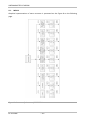
VII. Menu ................................................................................................................................. 16
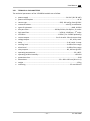
VIII. Technical parameters ....................................................................................................... 17
LIST OF FIGURES
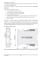
Figure 1 » VT1002DK dimension ............................................................................................... 4
Figure 2 » Exemplary installation of 3 VT1002DK modules on a DIN rail .................................. 7
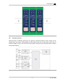
Figure 3 » VT1002DK isolation ................................................................................................... 7
Figure 4 » VT1002DK connectors ............................................................................................... 8
Figure 5 » VT1002DK current loop ............................................................................................. 9
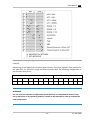
Figure 7 » Functions of configuration switches ....................................................................... 15
Figure 8 » Structure of the menu of VT1002DK ....................................................................... 16
EC SYSTEMS
–2–