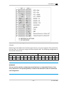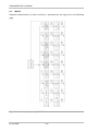
1
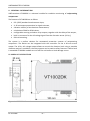
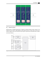
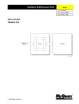
_EN_ VIBTRANSMITTER VT1002DK USER MANUAL VIBTRANSMITTER VT1002DK TABLE OF CONTENTS I. Introduction ........................................................................................................................ 3 II. General information ........................................................................................................... 4 III. Module description............................................................................................................. 4 IV. Front panel description ...................................................................................................... 5 IV.1. Measurement chain diagnostics for IEPE sensor ........................................................ 5 IV.2. Alarm outputs and proper work indicators ................................................................. 6 IV.3. Keyboard and measured value indicators ................................................................... 6 V. Installation and usage ......................................................................................................... 6 V.1. Mounting ..................................................................................................................... 6 V.2. Galvanic isolation ........................................................................................................ 7 V.3. Electrical connectors ................................................................................................... 8 V.4. AC Voltage output ....................................................................................................... 9 V.5. Activation..................................................................................................................... 9 VI. Configuration of the VT1002DK ........................................................................................ 10 VI.1. Entering the menu ..................................................................................................... 10 VI.2. Setting up of the alarm threshold – ‘A’..................................................................... 10 VI.3. Setting up of the warning threshold – ‘U’................................................................. 10 VI.4. Setting up of the threshold activation delay – ‘d’ ..................................................... 11 VI.5. Setting up the latch of alarm threshold or warning threshold violation – ‘L’ .......... 11 VI.6. Signaling of the sensor failure – ‘CA’, ‘CU’ .............................................................. 12 VI.7. Setting up the correction of values indicated by the module – ‘SC’ ....................... 13 VI.8. Turning display off on sensor failure – ‘Er’ ............................................................... 13 VI.9. Selecting the measured vibration signal estimate – ‘AU’......................................... 14 VI.10. Measurement parameter configuration ................................................................... 14 VII. Menu ................................................................................................................................. 16 VIII. Technical parameters ....................................................................................................... 17 LIST OF FIGURES Figure 1 » VT1002DK dimension ............................................................................................... 4 Figure 2 » Exemplary installation of 3 VT1002DK modules on a DIN rail .................................. 7 Figure 3 » VT1002DK isolation ................................................................................................... 7 Figure 4 » VT1002DK connectors ............................................................................................... 8 Figure 5 » VT1002DK current loop ............................................................................................. 9 Figure 7 » Functions of configuration switches ....................................................................... 15 Figure 8 » Structure of the menu of VT1002DK ....................................................................... 16 EC SYSTEMS –2– USER MANUAL _EN_ I. INTRODUCTION The following paragraph does not apply to countries where legal provisions do not comply to the conditions and terms described herein. EC SYSTEMS DOES NOT TAKE ANY LIABILITY CONCERNING THIS MANUAL, WHETHER EXPLICIT NOR IMPLIED (BUT NOT LIMITED TO); NOR CONCERNING A TYPICAL AVERAGE MARKET QUALITY OR THE FITNESS FOR ANY SPECIAL PURPOSE. In some countries and parts of some countries the exclusion and/or limitation of the duration of explicit or implied warranties concerning certain transactions are not allowed. Therefore the declaration above may be not effective in certain areas. This publication may contain erroneous information and/or typographic errors. The contained information is revised in an on-going process. So later editions can contain changes. Products/software described herein may be changed and improved at any time without any obligation to a prior announcement. Any product and company names mentioned herein may be protected trademarks. © COPYRIGHT The following document is the property of EC Systems, which reserves all the copyrights, patent-pending law and templates included. Copying or other abuse of this document or its parts, or sharing with third parties requires the written permission of EC Systems. –3– EC SYSTEMS VIBTRANSMITTER VT1002DK II. GENERAL INFORMATION VIBTransmitter VT1002DK is a universal module for condition monitoring of reciprocating compressors. The features of VT1002DK are as follow: ICP® (IEPE) standard accelerometer input, 4..20 mA output proportional to signal estimate, vibration velocity or acceleration measurement, calculation of RMS or PEAK values, configurable warning and alarm relay outputs, together with the delay of the output, built-in connector for the AC voltage signal from the vibration sensor (10 Vpp), DIN rail mounting. The system is a perfect solution for automated protection systems of reciprocating compresors. The device can be integrated with the controller via the 4..20 mA current output. The 10 Vpp AC voltage output allows to control the vibration level using a portable vibration analyzer. In addition, the relay outputs can be used as safety features. If alarm level is exceeded VT1002DK module can turn off the unit before critical damage occurs. III. MODULE DESCRIPTION Figure 1 » VT1002DK dimension EC SYSTEMS –4– USER MANUAL _EN_ The functionalities of the connectors indicated on the Figure 1 are as follow: 1. IEPE sensor circuit signalisation: open – open-circuit or sensor failure short – short-circuit or sensor failure 2. Signal estimate signalisation – one can choose form RMS or PEAK values; the choice is indicated by appropriate diode 3. Measured value signalisation – one can choose form velocity or acceleration 4. Presentation of the outputs states 5. Keyboard 6. 2-digit LED display 7. Power connector and sensor input 8. 4..20 mA current loop and relay-outputs connector 9. Set of configurable switches (SW2) 10. Set of configurable switches (SW1) 11. SMB connector for voltage vibration output signal IV. FRONT PANEL DESCRIPT ION IV.1. MEASUREMENT CHAIN DIAGNOSTICS FOR IEPE SENSOR Red LEDs – indicator of the sensor status: open – open circuit or sensor failure short – short circuit or sensor failure Green LEDs: indicator of the selected estimate: o RMS – RMS value of vibration signal o PEAK – maximum value of vibration signal (0-Peak) indicator of the selected measured value: o acc – acceleration o vel – velocity –5– EC SYSTEMS VIBTRANSMITTER VT1002DK IV.2. ALARM OUTPUTS AND PROPER WORK INDICATORS Alarm outputs indicators: red LED – ALARM – the alarm threshold exceeded, alarm output ON yellow LED – WARNING – the warning threshold exceeded, warning ON green LED – OK – proper work indicator: o diode pulsing with frequency of 1 Hz indicates the correct operation of the device o rapid pulsing means entering the device setup menu IV.3. KEYBOARD AND MEASURED VALUE INDICATORS Keyboard: UP – up DN – down SET – set Measured value – 2-digit LED display V. INSTALLATION AND USA GE V.1. MOUNTING VIBTransmitter VT1002DK module is designed for mounting on 35mm DIN rail in an upright position. Figure 2 presents the 3 VT1002DK modules mounted on a DIN rail. EC SYSTEMS –6– USER MANUAL _EN_ Figure 2 » Exemplary installation of 3 VT1002DK modules on a DIN rail V.2. GALVANIC ISOLATION VIBTransmitter VT1002DK guarantees full galvanic isolation between power supply of the module with the sensor, warning/alarm relay outputs and the current loop in the case of external supply of the 4..20 mA current loop. Figure 3 presents the schematic block of above mentioned isolation. Figure 3 » VT1002DK isolation –7– EC SYSTEMS VIBTRANSMITTER VT1002DK V.3. ELECTRICAL CONNECTORS Description of the connectors is presented on the Figure 4. Figure 4 » VT1002DK connectors EC SYSTEMS –8– USER MANUAL _EN_ 4..20 mA current connection is shown on the Figure 5. Figure 5 » VT1002DK current loop V.4. AC VOLTAGE OUTPUT The usage of the voltage output of the module should be performed according to Figure 6. Figure 6: VT1002DK AC voltage output V.5. ACTIVATION After connecting the power, the VT1002DK module enters into testing procedure. Subsequently all LEDs will flash for a short period of time. If everything is operating properly, then LED is pulsing with a frequency of approximately 1 Hz. Once the testing procedure is over, the device is ready to operate. If an error of a sensor circuit is detected, then corresponding LED will lit. –9– EC SYSTEMS VIBTRANSMITTER VT1002DK VI. CONFIGURATION OF THE VT1002DK The front panel of the VT1002DK module contains three buttons, labeled subsequently UP, DN and SET. These buttons are used to edit the module functions. VI.1. ENTERING THE MENU During normal operation of the VT1002DK module, pressing UP or DN button will cause entering into the device menu, which is indicated by rapid blinking of the OK LED. While in edit mode, buttons UP/DN scroll the menu items: A – alarm, U – warning, d – thresholds activation delay, L – latching of alarm threshold or warning threshold violation, CA – alarm activation in case of the sensor circuit failure, CU – warning activation in case of the sensor circuit failure, SC – correction of values indicated by the module, Er – turning display off on sensor failure, AU – selection of vibration signal estimate. VI.2. SETTING UP OF THE ALARM THRESHOLD – ‘A’ The VIBTransmitter VT1002DK has the ability to activate the built-in relay, when the signal from the vibration sensor exceeds the threshold value. To set the alarm threshold one should perform the following procedure: 1. Press UP/DN. Afterwards the OK LED will blink rapidly, which indicates entering into the device menu. 2. By pressing UP/DN set the letter ‘A’ on the display. 3. Confirm by pressing the SET button. 4. Use the UP/DN buttons to select the desired alarm threshold value in the range from 0.0 to 99. Alarm threshold value cannot be lower than the warning threshold value. 5. To confirm the change, press the SET button. If the vibration sensor signal will exceed the alarm threshold value and will remain above it for the time the configured delay, the alarm relay will be activated. To disable the alarm threshold, instead of the numerical value from the range from 0.0 to 99, set the ‘FF’ value on the display and confirm by pressing the SET button. VI.3. SETTING UP OF THE WARNING THRESHOLD – ‘U’ The second relay installed in the VT1002DK module is marked warning. It informs about excitation of the warning level of the vibration signal. EC SYSTEMS – 10 – USER MANUAL _EN_ To set the warning threshold one should perform the following procedure: 1. Press UP/DN. Afterwards the OK LED will blink rapidly, which indicates entering into the device menu. 2. By pressing UP/DN set the letter ‘U’ on the display. 3. Confirm by pressing the SET button. 4. Use the UP/DN buttons to select the desired alarm threshold value in the range from 0.0 to 99. Warning threshold value cannot be greater than the alarm threshold value. 5. To confirm the change, press the SET button. To disable the warning threshold, instead of the numerical value from the range from 0.0 to 99, set the ‘FF’ value on the display and confirm by pressing the SET button. VI.4. SETTING UP OF THE THRESHOLD ACTIVATION DELAY – ‘d’ In the VT1002DK module the user can define how long the alarm threshold or the warning threshold should be exceeded before activating the relay output. To set the delay one should perform the following procedure: 1. Press UP/DN. Afterwards the OK LED will blink rapidly, which indicates entering into the device menu. 2. By pressing UP/DN set the letter ‘d’ on the display. 3. Confirm by pressing the SET button. 4. Use the UP/DN buttons to select the desired delay time in the range from 0 to 16 s. 5. To confirm the change, press the SET button. VI.5. SETTING UP THE LATCH OF ALARM THRESHOLD OR WARNING THRESHOLD VIOLATION – ‘L’ VIBTransmitter VT1002DK has the ability to store the information about the violation of the warning or the alarm threshold. When the violation occurs, after the delay ‘d’, proper output is activated until the user erases the violation information by pressing the SET button. To set up the latch one should perform the following procedure: 1. Press UP/DN. Afterwards the OK LED will blink rapidly, which indicates entering into the device menu. 2. By pressing UP/DN set the letter ‘L’ on the display. 3. Confirm by pressing the SET button. 4. Use the UP/DN buttons to select the ON option. 5. To confirm the change, press the SET button. – 11 – EC SYSTEMS VIBTRANSMITTER VT1002DK To turn off the latch one should perform the following procedure: 1. Press UP/DN. Afterwards the OK LED will blink rapidly, which indicates entering into the device menu. 2. By pressing UP/DN set the letter ‘L’ on the display. 3. Confirm by pressing the SET button. 4. Use the UP/DN buttons to select the ‘oF’ option. 5. To confirm the change, press the SET button. VI.6. SIGNALING OF THE SENSOR FAILURE – ‘CA’, ‘CU’ For full control of the measurement chain VT1002DK can activate relay output when the measurement chain or vibration sensor is damaged. Sensor failure alarm can be attributed to the triggering alarm or warning relay. Triggering of the relay occurs after 5 seconds of open/short sensor failure. To set up the sensor failure signaling on the alarm output one should perform the following procedure: 1. Press UP/DN. Afterwards the OK LED will blink rapidly, which indicates entering into the device menu. 2. By pressing UP/DN set the ‘CA’ on the display. 3. Confirm by pressing the SET button. 4. Use the UP/DN buttons to select the ON option. 5. To confirm the change, press the SET button. To set up the sensor failure signaling on the warning output one should perform the following procedure: 1. Press UP/DN. Afterwards the OK LED will blink rapidly, which indicates entering into the device menu. 2. By pressing UP/DN set the ‘CU’ on the display. 3. Confirm by pressing the SET button. 4. Use the UP/DN buttons to select the ON option. 5. To confirm the change, press the SET button. To turn off the sensor failure signaling ‘CA’/’CU’ one should perform the following procedure: 1. Press UP/DN. Afterwards the OK LED will blink rapidly, which indicates entering into the device menu. 2. By pressing UP/DN set the ‘CA’/’CU’ on the display. 3. Confirm by pressing the SET button. 4. Use the UP/DN buttons to select the ‘oF’ option. 5. To confirm the change, press the SET button. EC SYSTEMS – 12 – USER MANUAL _EN_ VI.7. SETTING UP THE CORRECTION OF VALUES INDICATED BY THE MODULE – ‘SC’ The VT1002DK module is designed to work with ICP® (IEPE) accelerometers with sensitivity of 100 mV/g, however it is possible to set up set correction of values indicated by the module to adjust the module to a sensor with sensitivity slightly different than 100 mV/g. The ‘SC’ parameter indicates how much the presented values are being increased or decreased. To set correction of values indicated by the module one should perform the following procedure: 1. Press UP/DN. Afterwards the OK LED will blink rapidly, which indicates entering into the device menu. 2. By pressing UP/DN set the ‘SC’ on the display. 3. Confirm by pressing the SET button. 4. Use the UP/DN buttons to select the desired correction value within the -10 up to +10 range. Negative values are indicated by glowing decimal point on the right display. 5. To confirm the change, press the SET button. VI.8. TURNING DISPLAY OFF ON SENSOR FAILURE – ‘Er’ The module enables to mask the incorrect measurement values in the case of sensor circuit failure. Activating this feature results in display of the “--“ symbol in the case of open or short circuit. To enable the feature one should perform the following procedure: 1. Press UP/DN. Afterwards the OK LED will blink rapidly, which indicates entering into the device menu. 2. By pressing UP/DN set the ‘Er’ on the display. 3. Confirm by pressing the SET button. 4. Use the UP/DN buttons to select the ON option. 5. To confirm the change, press the SET button. To disable the feature one should perform the following procedure: 1. Press UP/DN. Afterwards the OK LED will blink rapidly, which indicates entering into the device menu. 2. By pressing UP/DN set the ‘Er’ on the display. 3. Confirm by pressing the SET button. 4. Use the UP/DN buttons to select the ‘oF’ option. 5. To confirm the change, press the SET button. – 13 – EC SYSTEMS VIBTRANSMITTER VT1002DK VI.9. SELECTING THE MEASURED VIBRATION SIGNAL ESTIMATE – ‘AU’ The VT1002DK module enables measuring RMS or 0-PEAK values of vibration acceleration or velocity. ATTENTION! The configuration must be confirmed using SW1 and SW2 configuration switches described in the following chapter (VI.10. Measurement parameter configuration). To select desired estimate one should perform the following procedure: 1. Press UP/DN. Afterwards the OK LED will blink rapidly, which indicates entering into the device menu. 2. By pressing UP/DN set the ‘AU’ on the display. 3. Confirm by pressing the SET button. 4. Use the UP/DN buttons to select one of the following option: a. ‘PU’ – 0-PEAK value of the velocity signal, b. ‘rU’ – RMS value of the velocity signal, c. ‘PA’ – 0-PEAK value of the acceleration signal, d. ‘rA’ – RMS value of the acceleration signal, 5. To confirm the change, press the SET button. VI.10. MEASUREMENT PARAMETER CONFIGURATION Measurement parameter configuration is set by proper set-up of configuration switches SW1 and SW2. Description of switches SW1 and SW2 is presented in the following table and Figure 7: Functions of configuration switches SW1 S1: ON – HPF = 10 Hz OFF – HPF = 3 Hz S2: ON – range 100 S3: ON – range 10 S4: ON – range 25 S5: ON –LPF = 300 Hz S6: ON –LPF = 10 kHz S7: ON – acceleration S8: ON – velocity EC SYSTEMS SW2 S1: ON – range 10 OFF – range 100 ON – range 25 OFF – range 100 ON – acceleration OFF – velocity S2: S3: S4: ON – RMS OFF – PEAK S5: ON – internal power supply +24 V for 4..20 mA S6: ON – external power supply for 4..20 mA – 14 – USER MANUAL _EN_ Figure 7 » Functions of configuration switches Example: Monitoring of the RMS of the vibration signal velocity, using 3 Hz high pass filter and 10 KHz low pass filter, for 100 mm/s range and internal power loop. The following configuration of the switches must be set: SW1 SW2 OFF ON OFF OFF OFF ON OFF ON OFF OFF OFF ON ON OFF 1 2 3 4 5 6 7 8 1 2 3 4 5 6 WARNING! The set-up of the switches configuration should be done on a switched off device. If the set-up was done on an operating module, it needs to be restarted in order to activate the new configuration. – 15 – EC SYSTEMS VIBTRANSMITTER VT1002DK VII. MENU Graphical representation of menu structure is presented on the Figure 8 on the following page. Figure 8 » Structure of the menu of VT1002DK EC SYSTEMS – 16 – USER MANUAL _EN_ VIII. TECHNICAL PARAMETERS The technical parameters of the VT1002DK module are as follow: power supply ................................................................................... 24 VDC (18..36 VDC) power consumption .................................................................................................<4 W sensor type ....................................................................... IEPE, 100 mV/g, 8 mA @ 20 V measured values .............................................................................velocity, acceleration types of estimates ....................................................................................... RMS, 0-PEAK low-pass filter .........................................................300 Hz/10 kHz, 24 dB/oct., 4th order high-pass filter .................................................................. 3/10 Hz, 12 dB/oct., 2nd order insulation ....................................................................... 1 kVDC (2 or 3 kVDC optionally) current output .......................................................... 2 or 3 wired 4..20 mA current loop voltage output ......................................................................................... AC, 10 Vpp max. delay .................................................................................................. 0-16 s with 1 s step warning level ..................................................................................... 0-99% of the range alarm level ......................................................................................... 0-99% of the range relay outputs..................................................................................... NC, 100 mA @ 24 V operating temperature .................................................................................... -20..+60°C operating relative humidity ................................................................................<95% RH protection class.......................................................................................................... IP40 dimensions....................................................................... 23 x 100 x 120 mm (W x H x L) weight ...................................................................................................................... 150 g mounting .................................................................................................. 35 mm DIN rail – 17 – EC SYSTEMS VIBTRANSMITTER VT1002DK EC Systems Sp. z o.o. Lublanska 34 31-476 Krakow POLAND Phone: +48 12 627 77 40 Sales: +48 12 627 77 23 Fax: +48 12 627 77 11 e-mail: [email protected] EC SYSTEMS – 18 –