1
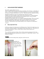
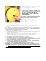
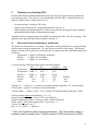
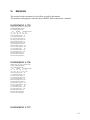
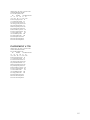
Webb Research Corporation
82 Technology Park Drive, E. Falmouth, MA 02536-4441 (508) 548-2077 FAX (508) 540-1686
USER MANUAL – APEX-SBE PROFILER
Serial #3795~3798
REV DATE: 01/29/08
WRC Job no. 1308 INNOVA.
Software Rev 05-18-04
Type Park and Profile(x2) with 28-bit ID
I.
ALKALINE BATTERY WARNING...............................................................................................................2
II.
RESET AND SELF TEST.................................................................................................................................2
III.
DEPLOYMENT ............................................................................................................................................4
IV.
PARK AND PROFILE(X2) FEATURE .....................................................................................................4
V.
ARGOS DATA ...................................................................................................................................................6
A.
B.
C.
D.
E.
F.
G.
VI.
SERVICE ARGOS PARAMETERS ..............................................................................................................6
DATA FORMAT (NO 19) FOR 28-BIT ARGOS ID .........................................................................................6
TIMESTAMPS ....................................................................................................................................................8
DEPTH TABLE NO. 64 ......................................................................................................................................9
TEST MESSAGE FORMAT ........................................................................................................................11
TELEMETRY ERROR-CHECKING (CRC) ...........................................................................................................13
CONVERSION FROM HEXADECIMAL TO USEFUL UNITS ....................................................................................13
MISSIONS ...................................................................................................................................................14
APPENDIX A: FLAG BYTE DESCRIPTION......................................................................................................16
APPENDIX B: CRC ALGORITHM IN BASIC FOR 28 BIT ID.......................................................................18
APPENDIX C: SURFACE ARRIVAL TIME, AND TOTAL SURFACE TIME ..............................................19
APPENDIX D: ARGOS ID FORMATS, 28 BIT AND 20 BIT .............................................................................21
APPENDIX E: STORAGE CONDITIONS ...........................................................................................................21
APPENDIX G: RETURNING APEX FOR FACTORY REPAIR OR REFURBISHMENT ............................21
APPENDIX G: CTD CALIBRATION AND BALLASTING RECORDS..........................................................22
I.
ALKALINE BATTERY WARNING
The profiler contains alkaline "D" cells.
There is a small but finite possibility that batteries of alkaline cells will release a combustible gas
mixture. This gas release generally is not evident when batteries are exposed to the atmosphere,
as the gases are dispersed and diluted to a safe level. When the batteries are confined in a sealed
instrument mechanism, the gases can accumulate and an explosion is possible.
Webb Research Corp. has added a catalyst inside of these instruments to recombine Hydrogen
and Oxygen into H2O, and the instrument has been designed to relieve excessive internal
pressure buildup by having the upper end cap release.
Webb Research Corp. knows of no way to completely eliminate this hazard. The user is warned,
and must accept and deal with this risk in order to use this instrument safely as so provided.
Personnel with knowledge and training to deal with this risk should seal or operate the
instrument. Webb Research Corp. disclaims liability for any consequences of combustion or
explosion.
II.
Reset and Self Test
Profilers are shipped to the deployment site in Hibernate mode. Shortly before deployment, reset
the profiler by passing a magnet over the marked location on the pressure case. The profiler will
run a self-test, transmit for 6 hours with the bladder extended, and then begin its preprogrammed mission.
The six ARGOS transmissions during self-test and the transmissions during the initial 6 hour
period contain data about the instrument and are outlined in (V) ARGOS DATA, part (C) TEST
MESSAGE FORMAT.
Procedure:
1. Secure float in horizontal position, using foam cradles from crate.
IMPORTANT:
Remove plastic bag
and three plugs from
CTD sensor, if they
have not already been
removed.
2
2. Minimum temperature –2 deg C. If necessary, let
float warm indoors before proceding.
3. Carefully remove black rubber plug from bottom
center of yellow cowing to verify bladder inflation
(per below). Use fingers only- tools may
puncture bladder. Be sure to replace plug
before deployment.
Note: it can be very difficult to replace plug when air
bladder is fully inflated. Replace plug during
beginning of air bladder inflation.
Purpose of plug is to prevent silt entry if float
contacts sea floor.
4. Hold provided magnet at RESET position marked on for several seconds, then remove
magnet.
Note: Magnetic switch must be activated (held) for at least one second to reset the instrument.
(This is to provide a safety against accidental reset during transport.) Thus, if the float does not
respond as below, the instrument was probably not reset.
5. The air pump will operate for 1 second.
6. The PTT will transmit 6 times at 6 second intervals. Place ARGOS receiver/beeper close to
antenna to detect transmissions.
7. The piston pump will begin to operate. The piston will move to the retracted Storage
Position, if not already there, pause 2 seconds and then move to full extension.
8. The oil bladder will expand, this should take 15 - 25 minutes.
9. After the piston pump stops, PTT will transmit at specified ARGOS rate.
10. At every PTT transmission, the air pump will turn on for 6 seconds until the air portion of the
bladder has been inflated. The pump should turn on 8 – 10 times.
11. 6 hours after reset, transmissions will cease, the bladder will deflate, and the piston pump
will retract, the profiler begins its programmed mission.
12. Reminder - replace black rubber plug in cowling hole before deployment.
During self-test, the controller checks the internal vacuum sensor. If the internal pressure has
increased above a preset limit (i.e. hull leakage caused loss of vacuum), the instrument will not
pump. If you do not detect the 6 test transmissions, and if the bladder does not inflate, then
the self-test has failed and the instrument should not be deployed!
3
III.
Deployment
− RESET instrument.
− SELF-TEST starts automatically (see above).
− When piston pump stops, air pump inflates, external bladder is full, PTT will transmit for 6
hours at ARGOS Repetition rate intervals. Typical repetition rate is 90 seconds or less.
Programmed repetition rate can be found in the Missions section of this manual.
− If the repetition rate is 120 seconds the controller is not communicating properly with the
CTD and the float should not be deployed.
− Six hours after reset, the piston pump will retract and bladder will deflate. Deploy before
this time is up or reset the instrument again to re-initialize the 6 hour period. The purpose is
to have the instrument on the surface and receive test transmissions.
− Pass a rope through the hole in the damper plate.
− Holding both ends of doubled up rope, carefully lower the float into the water. Do not let
rope slide through hole in disk- this may cut the plastic disk.
− Take care not to damage the antenna.
− Do not leave the rope with the instrument, release one end and retrieve the rope.
− The float will remain on the surface until the 6 hour interval has expired.
IV.
PARK and PROFILE(x2) Feature
4
The optional park and profile feature allows the float to drift (i.e. “park”) at an intermediate
depth, then descend to a greater depth before making profile measurements during ascent to the
surface.
The park and profile(x2) feature allows use of two profile depths in a programmed
sequence.
Terminology:
PARK:
intermediate depth at which the float drifts (menu parameter P1)
PROFILE: deeper depth to which the float descends before profiling up (parameters P6 and PF)
DOWN time: spent during descent and at park depth (parameters D1 and D2)
UP time: includes ascent and time at surface (parameters U1 and U2)
Cycle timing (UP and DOWN times) are defined by:
parameters U1 and D1 for profile pressure P6
parameters U2 and D2 for profile pressure PF.
The sequence of profile pressures is set by parameter PD.
For example, if PD is set to 10:
profile pressure P6 occurs during cycles 1, 11, 21…
profile pressure PF occurs during cycles 2-10, 12-20…
Ascent rate: approximately .08 meters per second.
Total Up time is typically set to 12 to 20 hours, increasing proportional to depth and amount of
data to be transmitted per profile. Another factor is deployment location: due to the polar orbit
of ARGOS, the number of passes per day increases at high latitudes.
DOWN time
D
E
P
T
H
UP time
Surface
Park
Profile
TIME
SCHEMATIC: Depth versus Time
Parameter PD determines the frequency of deep profiles.
Schematic examples:
5
PD = 1
deep profile every cycle
V.
PD = 2
deep profile every 2nd cycle
ARGOS DATA
A.
SERVICE ARGOS PARAMETERS
The user must specify various options to Service ARGOS. These choices depend on how the
user wishes to receive and process data. Typical parameters are listed below:
− Standard location.
− Processing: Type A2 (pure binary input; hexadecimal output)
− Results Format: DS (all results from each satellite pass), Uncompressed.
− Distribution Strategy: Scheduled, all results, every 24 hours.
− Number of bytes transmitted: 31 per message*
Note: Webb Research strongly recommends all users to use ARGOS “Multi Satellite Service”,
which provides receptions from 3 satellites instead of 2 for a small incremental cost.
* Using Argos 28-bit ID Format, 31 data bytes are transmitted in each message. With 20-bit ID
Format, each message had 32 data bytes. (see Appendix D for more information).
B.
DATA FORMAT (no 19) for 28-bit ARGOS ID
Data are sent via ARGOS in 31 byte hex messages. The number of 31 byte messages sent
depends on the programmed quantity of temperature measurements per profile.
6
Format for message number 1 only:
Byte #
− 01 CRC, described in section C.
− 02 Message number, Assigned sequentially to each 32 byte message (Total number of
messages per profile is shown below). Messages are transmitted in sequential order starting
with 1 and incrementing by one for the data set.
− 03 Message block number, begins as 1 and increments by one for every ARGOS message
data set. This, combined with the ARGOS repetition rate (section VI), allows the user to
track surface drift. Byte 03 will roll-over at 256 and will reset to 1 on each new profile.
− 04 & 05 Serial number, identifies the controller board number. (This may not be the same
as instrument number.)
− 06 Profile number, begins with 1 and increases by one for every float ascent.
− 07 Profile length, is the number of six byte STD measurements in the profile. Total
number of bytes of STD data from each profile depends on the sampling strategy chosen.
− 08 Profile termination flag byte 2 -see section D
− 09 Piston position, recorded as the instrument reaches the surface.
− 10 Format Number (identifier for message one type)
− 11 Depth Table Number (identifier for profile sampling depths)
− 12 & 13 Pump motor time, in two second intervals. (multiply by 2 for seconds)
− 14 Battery voltage, at initial pump extension completion
− 15 Battery current, at initial pump extension completion, one count = 13 mA
− 16 Profile 1 piston position (park and profile floats only)
− 17 Profile 2 piston position
− 18 Air bladder pressure measured in counts - approximately 148 counts
− 19 & 20 Park temperature, sampled just before instrument descends to target depth.*
− 21 & 22 Park salinity, sampled just before instrument descends to target depth.*
− 23 & 24 Park pressure, sampled just before instrument descends to target depth.*
− 25 Park battery voltage, no load
− 26 Park battery current
− 27 & 28 Surface Pressure, as recorded just before last descent with an offset of +5 dbar
− 29 Internal vacuum measure in counts- approximately 101 counts
− 30 Park piston position*
− 31 SBE pump Voltage
7
Format for message number 2
Byte #
− 01CRC, described in section C.
− 02 Message number
− 03 & 04 time of profile start
− 05 & 06 first profile temperature
− 07 & 08 first profile salinity
− 09 & 10 first profile pressure
− 11 to 31 6 bytes- in sequence and continuing in the next message**
2 bytes temperature
2 bytes salinity
2 bytes pressure
**Note some byte pairs will split between messages.
Format for message number 3
Byte #
− 01CRC, described in section C.
− 02 Message number
− 03 ~ 31 temperature, salinity, pressure points per depth table
Sampling continues as shown above, per the depth table.
After the last data point in last message, two bytes surface detect time will be followed by a Hex
value of FF filing remaining bytes.
C.
Timestamps
As mentioned above, two timestamps are included:
The first timestamp (bytes 03 & 04 of message no. 2) marks start of upcast profile.
The second timestamp (2 bytes preceded by the shallowest pressure value, followed by FF filling
remaining bytes of last message) marks detection of (surface pressure + 5 db).
Each time count equals two seconds elapsed since the float was reset. The clock resets to zero
every 24 hours.
8
D.
Depth Table No. 64
Sample Pressure Sample Pressure Sample Pressure
Point
(dbar)
Point
(dbar)
Point
(dbar)
Bottom
1
2
3
4
5
6
7
8
9
10
11
12
13
14
15
16
17
18
19
20
21
22
23
24
25
26
27
28
29
30
31
32
33
34
35
36
2000
1950
1900
1850
1800
1750
1700
1650
1600
1550
1500
1450
1400
1350
1300
1250
1200
1150
1100
1050
1000
950
900
850
800
750
700
690
680
670
660
650
640
630
620
610
37
38
39
40
41
42
43
44
45
46
47
48
49
50
51
52
53
54
55
56
57
58
59
60
61
62
63
64
65
66
67
68
69
70
71
72
600
590
580
570
560
550
540
530
520
510
500
490
480
470
460
450
440
430
420
410
400
390
380
370
360
350
340
330
320
310
300
290
280
270
260
250
73
74
75
76
77
78
79
80
81
82
83
84
85
86
87
88
89
90
91
92
93
94
95
96
97
98
99
100
101
102
103
104
105
106
240
230
220
210
200
190
180
170
160
150
140
130
120
110
100
95
90
85
80
75
70
65
60
55
50
45
40
35
30
25
20
15
10
4
9
APEX records a profile during ascent (ie upcast). Pressure is measured every 6 seconds during
ascent. Whenever pressure is equal to or less than a value in the depth table, a CTD sample is
recorded. The first (i.e. deepest) sample is taken at the first point in the depth table above
bottom pressure.
The SeaBird CTD is not sampled at zero pressure, to avoid pumping the cell dry and/or
ingesting surface oil slicks. The shallowest profile point is taken at either 4 dbar or at the last
recorded surface pressure plus 5 dbar, whichever value is larger.
The number of sample points (ie profile length) will be reduced if the float is unable to reach
intended depth for any reason. Bottom pressure may change due to several causes, such
variation of insitu density, internal waves, float grounding in shallows, change of float mass, etc.
APEX automatic depth adjustment will compensate in most, but not all, cases.
10
E.
TEST MESSAGE FORMAT
The test message is sent whenever an I2 command is given, the six transmissions during the
startup cycle, and during the six hour surface mode period prior to the first dive. Each test
message has 31 Bytes, in hex unless otherwise noted, with the following format:
Test message #1
Byte #
− 01 CRC, described in section C.
− 02 message number ( = 01)
− 03 Message block number, begins as 1 and increments by one for every ARGOS message.
− 04 & 05 Serial number, identifies the controller board number. (This may not be the same
as instrument number.)
− 06 & 07 & 08 Time from start up HR:MIN:SEC
− 09 Flag (2) Byte
− 10 & 11 Present CTD pressure, in bar
− 12 Battery voltage
− 13 Present bladder pressure, in counts
− 14 Flag (1) Byte
− 15 Up time one in hours
− 16 Up time two, in hours
− 17 & 18 Down time one, in hours
− 19 & 20 Down time two, in hours
− 21 Ascend time one, in hours
− 22 Ascend time two, in hours
− 23 & 24 park pressure in counts
− 25 Park piston position, in counts
− 26 Depth correction factor, in counts
− 27 Storage piston position (P4), in counts
− 28 Fully extended piston position (P5), in counts
− 29 Month, software version number (in decimal).
− 30 Day, software version number (in decimal).
− 31 Year, software version number (in decimal).
−
* Flag (2) byte: 1 Deep profile
**Flag (1) byte: 1 Trip interval time
2 Pressure reached zero
2 Profile in progress
3 25 minute Next Pressure timeout
3 Timer done
4 piston fully extended before surface
4 UP/ DOWN
5 Ascend time out
5 Data entry error
6 Test message at turn on
6 Measure battery
7 Six hour surface message
7 Piston motor running
8 Seabird String length error
8 Negative SBE no.
11
Test message #2
Byte #
−
−
−
−
−
−
−
−
−
−
−
−
−
−
−
−
−
−
−
−
−
−
−
−
−
−
01 CRC, described in section C.
02 message number (= 02)
03 Message block number, begins as 1 and increments by one for every ARGOS message.
04 & 05 Serial number, identifies the controller board number. (This may not be the same
as instrument number.)
06 & 07 & 08 Time from start up HR:MIN:SEC
09 Flag (2) Byte
10 & 11 Current pressure, in bar
12 Battery voltage
13 Current Bladder pressure, in counts
14 Flag (1) Byte
15 Park pressure (least significant byte only)
16 park piston position
17 depth correction factor
18 Storage piston position
19 Full Piston position
20 OK Vacuum count
21 Max Air Bladder Pressure
22 & 23 profile 1 pressure
24 profile 1 piston position
25 deep profile cycle count
26 & 27 profile 2 pressure
28 profile 2 piston position
29 Month, software version number (in decimal).
30 Day, software version number (in decimal).
31 Year, software version number (in decimal).
12
F.
Telemetry error-checking (CRC)
Because ARGOS data contains transmission errors, the first byte of each message contains an
error checking value. This value is a Cyclic Redundancy Check (CRC), and is calculated as a
function of the message content (bytes 2 to 32).
− For each message, calculate a CRC value
− Compare the calculated CRC to the transmitted CRC (byte no. 2)
− If the calculated and transmitted CRC values are not equal, the message has been corrupted
and should be deleted before further data processing.
Appendix (B) lists a sample program (in BASIC) to calculate the CRC value for a message. This
program can be provided upon request in Basic, Fortran or C
G.
Conversion from hexadecimal to useful units
The pressure is measured every 6 seconds. Temperature, salinity and pressure are measured and
stored at each point in the depth table. Two hex bytes are stored for each sensor. The decimal
numbers from the STD sensors are converted to hex for compression in the ARGOS transmission
as follows:
Temperature: 5 digits, 1 milli-degree resolution.
Salinity:
5 digits, .001 resolution
Pressure:
5 digits, 10 cm resolution.
To convert the hex ARGOS message back to decimal numbers:
hex →
dec
=
converted
Temperature: 3EA6 →
16038 =
16.038
Temperature*: F58B →
02677 =
-2.677
Salinity**:
8FDD →
36829 =
36.829
Pressure:
1D4C →
7500 =
750.0
Current
0A→
10 =
130
Volts
99 →
153 =
15.7
units
C
C
decibars
mA
volts
Voltage (V) = counts/10 + .4 (counts is in decimal number) nominally 15 V and decreasing.
Current (mA) = counts *13 (counts is in decimal number)
Vacuum (inHg) = counts *-0.209 + 26.23 (counts is in decimal number) nominally 5 inHg.
*Note regarding negative temperatures ( T °C < 0 )
Positive temperature range is 0 to 62.535C (0 to F447 hex)
Negative temperature range is -0.001 to -3.000C (FFFF to F448 hex).
If (hex value) > F448, then compute FFFF - (hex value) = Y
Convert Y to decimal = dec_Y
(dec_Y + 1) / 1000*-1 = degrees C
**The 5 most significant salinity digits are telemetered. The 6 digit salinity number is
rounded up and converted to hex. 36.8286 rounds to 36.829 and converts to 8FDD.
13
VI.
MISSIONS
This section lists the parameters for each float covered by this manual.
The parameter listing appears when the float is RESET while connected to a terminal.
INSTRUMENT # 3795
APEX version 05 18 04 sn 3727 019 064
38421BE ARGOS ID number.
030 seconds repetition rate.
UP
DOWN
ASCEND in hours:
U1 U2 D1 D2 T1 T2
014 008 106 112 009 006
0350 d-bar park pressure. P1
115 park piston position. P2
012 ascent rate correction. P3
100 storage piston position. P4
248 piston full extension. P5
2000 d-bar profile pressure. P6
025 profile piston position. P7
0700 d-bar PFL 2 pressure. PF
075 PFL 2 piston position. PG
115 OK vacuum count.
P8
149 air bladder pressure. PB
010 deep profile count. PD
025 Initial piston extension.
006 hours sink to depth one.
003 hours sink to depth two.
INSTRUMENT # 3796
APEX version 05 18 04 sn 3728 019 064
38421C7 ARGOS ID number.
028 seconds repetition rate.
UP
DOWN
ASCEND in hours:
U1 U2 D1 D2 T1 T2
014 008 106 112 009 006
0350 d-bar park pressure. P1
115 park piston position. P2
012 ascent rate correction. P3
100 storage piston position. P4
249 piston full extension. P5
2000 d-bar profile pressure. P6
025 profile piston position. P7
0700 d-bar PFL 2 pressure. PF
075 PFL 2 piston position. PG
115 OK vacuum count.
P8
149 air bladder pressure. PB
010 deep profile count. PD
025 Initial piston extension.
006 hours sink to depth one.
003 hours sink to depth two.
INSTRUMENT # 3797
14
APEX version 05 18 04 sn 3729 019 064
38421D4 ARGOS ID number.
032 seconds repetition rate.
UP
DOWN
ASCEND in hours:
U1 U2 D1 D2 T1 T2
014 008 106 112 009 006
0350 d-bar park pressure. P1
115 park piston position. P2
012 ascent rate correction. P3
100 storage piston position. P4
248 piston full extension. P5
2000 d-bar profile pressure. P6
025 profile piston position. P7
0700 d-bar PFL 2 pressure. PF
075 PFL 2 piston position. PG
115 OK vacuum count.
P8
149 air bladder pressure. PB
010 deep profile count. PD
025 Initial piston extension.
006 hours sink to depth one.
003 hours sink to depth two.
INSTRUMENT # 3798
APEX version 05 18 04 sn 3730 019 064
38421E1 ARGOS ID number.
030 seconds repetition rate.
UP
DOWN
ASCEND in hours:
U1 U2 D1 D2 T1 T2
014 008 106 112 009 006
0350 d-bar park pressure. P1
115 park piston position. P2
012 ascent rate correction. P3
100 storage piston position. P4
249 piston full extension. P5
2000 d-bar profile pressure. P6
025 profile piston position. P7
0700 d-bar PFL 2 pressure. PF
075 PFL 2 piston position. PG
115 OK vacuum count.
P8
149 air bladder pressure. PB
010 deep profile count. PD
025 Initial piston extension.
006 hours sink to depth one.
003 hours sink to depth two.
15
Appendix A: Flag Byte Description
Two memory bytes are used, one bit at a time, to store 16 different bits of program flow
information. Both of these bytes are telemetered in the test messages sent at startup and for the
initial 6 hour surface period. Only flag byte 2 is sent in the data messages, as part of message
number 1. Bit one is set for each deep profile and bit 8 is set each time the last SBE sensor value
used an arithmetic round up.
Below is a list of what each bit in each byte signifies.
bit
Flag (2) byte: 1 Deep profile
2 Pressure reached zero
3 25 minute NextP timeout
4 Piston fully extended
5 Ascend timed out
6 Test message at turn on
7 Six hour surface message
8 Seabird string length error
bit
Flag (1) byte: 1 Trip interval time
2 Profile in progress
3 Timer done (2 min bladder deflate time.)
4 UP/DOWN
5 Arithmetic round up
6 Measure battery while pumping
7 Piston motor running
8 Negative SBE number
The flag bytes are transmitted as two hex characters with four bits of information encoded in
each character. Each hex character can have one of 16 different values as shown in the
following table.
1
0
0000
10
9
1001
2
1
0001
11
A
1010
3
2
0010
12
B
1011
4
3
0011
13
C
1100
5
4
0100
14
D
1101
6
5
0101
15
E
1110
7
6
0110
16
F
1111
8
7
0111
9
8
1000
Bit 8 is the most significant bit and bit 1 is the least significant bit in the byte.
16
As an example: if a deep profile ended with the piston fully extended and ascend had timed out,
then bits 1, 4 and 5 would be set in the termination byte. This binary pattern, 0001 1001, would
be transmitted as the two hex characters, 19.
As another example: if a regular profile ended with the piston fully extended and the 25 minute
next pressure had timed out, then bits 3 and 4 would be set in the termination
byte. This binary pattern, 0000 1100, would be transmitted as the two hex characters, 0C.
17
Appendix B: CRC Algorithm in BASIC for 28 bit Id
Below is a sample program (in BASIC) to calculate the CRC value for a message. This program
can be provided upon request in Basic, Fortran or C.
DECLARE FUNCTION CRC% (IN() AS INTEGER, N AS INTEGER)
‘CRC routine to check data validity in ARGOS message.
‘Bathy Systems, Inc. RAFOS Float data transmission.
‘3 December, 1990.
‘The 1st of 31 bytes in an ARGOS message is the CRC.
‘The function CRC will compute CRC for byte 2 through 31.
‘Hasard is used for Random because Random is reserved by BASIC.
‘Stored as file CRC in C:\RAFOS\RAF11.
DECLARE SUB Hasard (ByteN AS INTEGER)
DEFINT A-Z
DIM in(31) AS INTEGER
‘RAF11F message number 08 HEX ID 11502 01-02-93 CRC is O.K.
A$ = "d802075d87c64e15078187c64c1f07b287c74a3007ce87c6483f07fe87c246"
N = 31
FOR I = 1 to N
in(I) = VAL(“&H” + MID$(A$, 2 + I - 1, 2))
NEXT I
PRINT in(1); CRC(in(), N);
FUNCTION CRC% (IN() AS INTEGER, N AS INTEGER) STATIC
DIM ByteN as INTEGER
I=2
ByteN = in(2)
DO
CALL Hasard(ByteN)
I=I+1
ByteN = ByteN XOR in(I)
LOOP UNTIL I = N
CALL Hasard (ByteN)
CRC = ByteN
END FUNCTION
DEFINT A-Z
SUB Hasard (ByteN AS INTEGER) STATIC
x% = 0
IF ByteN = 0 THEN ByteN = 127: EXIT SUB
IF (ByteN AND 1) = 1 THEN x% = x% + 1
IF (ByteN AND 4) = 4 THEN x% = x% + 1
IF (ByteN AND 8) = 8 THEN x% = x% + 1
IF (ByteN and 16) = 16 THEN x% = x% + 1
IF (X% AND 1) = 1 THEN
ByteN = INT(ByteN / 2) + 128
ELSE
ByteN = INT(ByteN / 2)
END IF
END SUB
18
Appendix C: Surface arrival time, and total surface time
Some users may wish to determine surface arrival time, and total surface time, in order to
calculate drift vectors.
Although each 31-byte message is time-stamped by ARGOS, there may not be a satellite in view
when the float surfaces.
When the float surfaces (ie detects surface pressure recorded before last descent) it will begin
ARGOS telemetry. Messages are transmitted in numerical order, starting with message no. 1.
When all messages have been transmitted, the cycle starts again at message no. 1.
Elapsed time since surfacing (Te)
Te = (m-1)*n*r
Where: m = message block number (byte 03 of message 01)
n = total number of messages to transmit profile
r = repetition rate
Total number of messages (n) is described in section IV (b), or may be determined from
the ARGOS data. Note (n) may be less than specified in user manual if the float is operating in
shallow water, causing reduced profile length.
Repetition rate (r) is the time interval between ARGOS transmissions. This value can be
determined from section V, or from the ARGOS data.
Approximate time of surfacing
Subtracting Te from the ARGOS time stamp can determine approximate time of surfacing
Example
Below is message 01 in DS format
2001-11-02 22:47:54 1 CF 01 05 02
AF 02 2F 00
85 01 01 01
16 92 17 19
9E 94 01 AD
85 09 1F 48
97 9B 00 46
62 24 0E
m=
n=
message block number (byte 03) = 5
total number of messages to transmit profile = 11
19
r=
repetition rate = 62 seconds
Te = elapsed time since surfacing = (m-1)*n*r = (5-1)*11*62 s = 2728 s = 00h 45m 28s
Approximate time of arrival at surface:
ARGOS time stamp - Te = 22:47:54 - 00:45:28 = 22:02:26
Total time spent at surface transmitting (Tsurf):
This is determined by subtracting ascent time from UP time.
Tsurf = (UP time, hr) - (bottom pressure)/(ascent rate 0.08 dbar/s)/3600
Bottom pressure is telemetered as bytes 7 & 8 of message 02.
Example:
For bottom pressure of 2000 dbar, and UP time of 18 hours
Tsurf = (18 hr) - (2000/0.08/3600) = 11 hr
20
APPENDIX D: Argos ID formats, 28 bit and 20 bit
In 2002 Service Argos notified its users there were a limited number of 20-bit Ids available and
to begin preparing for a transition to 28-bit IDs. The 28 bit-IDs reduced from 32 to 31 the
number of data bytes in each message. Data provided by Argos will consist of 31 hex bytes per
message. Data acquired by use of an uplink receiver will consist of 32 hex bytes per message.
The first byte, when using an uplink receiver, is a 28-bit ID identifier used by Argos and is not
represented in the Apex Data formats included in this manual.
APPENDIX E: Storage conditions
For optimum battery life, storage temperature range is +10 to +25 degrees C. When activated,
the floats should be equilibrated at a temperature between -2 and +54 degrees C.
If optional VOS or aircraft deployment containers are used, these must be kept dry, and should
be stored indoors only.
APPENDIX G: Returning APEX for factory repair or refurbishment
Contact WRC before returning APEX floats for repair or refurbishment.
All returns from outside USA, please specify our import broker:
Logan International Airport, Boston
c/o DHL-Danzas Freight Forwarding Agents,
Phone (617) 886-5605, FAX (617) 241-5917
500 Rutherford Avenue, Charlestown, MA 02129
Note on shipping documents: US MADE GOODS
21
APPENDIX G: CTD Calibration and Ballasting records
22