1
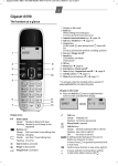
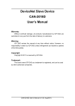
DeviceNet Slave Device
CAN-2054D
User’s Manual
Warranty
Without contrived damage, all products manufactured by ICP DAS are
warranted in one year from the date of delivery to customers.
Warning
ICP DAS revises the manual at any time without notice. However, no
responsibility is taken by ICP DAS unless infringement act imperils to patents
of the third parties.
Copyright
Copyright © 2010 is reserved by ICP DAS.
Trademark
The brand name ICP DAS as a trademark is registered, and can be used
by other authorized companies.
CAN-2054D User’s Manual (v1.00, July/2010)
1
Contents
1
2
3
Introduction.............................................................................................3
1.1 Overview.........................................................................................3
1.2 Hardware Specifications ...............................................................4
1.3 Features..........................................................................................5
1.4 Application .....................................................................................5
Hardware .................................................................................................6
2.1 Structure.........................................................................................6
2.2 Node ID & Baud Rate Rotary Switch ............................................7
2.3 LED Description.............................................................................8
2.4 PIN Assignment ...........................................................................10
2.5 Wire Connection .......................................................................... 11
DeviceNet Profile Area .........................................................................12
3.1 DeviceNet Statement of Compliance..........................................12
3.2 Identity Object (Class ID: 0x01) ..................................................13
3.3 Connection Object (Class ID:0x05) ............................................14
3.4 Assembly Object (Class ID: 0x04) ..............................................15
3.5 Application Object1 (Class ID: 0x64)..........................................17
4 Application ............................................................................................19
Appendix A: Dimension...............................................................................21
CAN-2054D User’s Manual (v1.00, July/2010)
2
1 Introduction
1.1 Overview
DeviceNet is one kind of the network protocols based on the CAN bus
and mainly used for the embedded network of the machine control, such as
industrial machine control , aircraft engines monitoring, factory automation,
medical equipments control, remote data acquisition, environmental
monitoring, and packaging machines control, etc.
The CAN-2054D follows DeviceNet specification Volume I/II, Release 2.0.
User can access the digital I/O status and set the configuration via DeviceNet
EDS file. This module has 8-channel isolated sink/source input and 8-channel
isolated sink output. It can be applied to various applications, such as PNP,
NPN, TTL, relay contact and so forth. By owing to the DeviceNet masters of
ICP DAS, you can quickly build a DeviceNet network to approach your
requirements.
CAN-2054D User’s Manual (v1.00, July/2010)
3
1.2 Hardware Specifications
Digital Output:
z Output Channels: 8 (Sink)
z DO Load Voltage: +5 ~ +30 VDC
z Output Max Load Current: 700 mA per channel.
z Output Type: Open Collector.
z Intra-module Isolation: 3750 Vrms
z ESD Protection: 4 kV Contact for each channel
Digital Input:
z Input Channels: 8 (Sink/Source).
z DI On Level: +3.5 ~ +30 VDC.
z DI Off Level: +1VDC Max.
z
z
z
Input Impedance: 3 kΩ, 0.3 W.
Intra-module Isolation: 3750 Vrms
ESD Protection: 4 kV Contact for each channel
Others:
z DeviceNet Status: 3 LEDs for PWR / NET / MOD.
z Terminator Resister: 1 LED as terminator resister indicators
z DI LED: 8 LEDs as digital input indicators.
z DO LED: 8 LEDs as digital output indicators.
z Power Supply: Unregulated +10 ~ +30 VDC.
z Power Consumption: 1.5 W.
z Operating Temperature: -25 ~ 75 ℃.
z Storage Temperature: -30 ~ 80 ℃.
z
z
Humidity: 10 to 90% RH, Non-condensing.
Dimensions: 32.3 mm x 99 mm x 77.5 mm (W x L x H) Detail.
CAN-2054D User’s Manual (v1.00, July/2010)
4
1.3 Features
z
z
DeviceNet general I/O slave devices.
Comply with DeviceNet specification Volume I, Release 2.0 &
Volume II, Release 2.0, Errata 5
Group 2 Only Server (non UCMM-capable)
Support Predefined Master/Slave Connection Set
Connection supported:
1 connection for Explicit Messaging
1 connection for Polled I/O
1 connection for Bit-Strobe I/O connection
Support DeviceNet heartbeat and shutdown messages
Provide EDS file for standard DeviceNet master interface.
z
NET, MOD and PWR Led indictors
z
z
z
z
z
1.4 Application
CAN-2054D User’s Manual (v1.00, July/2010)
5
2 Hardware
2.1 Structure
(Top View)
(Bottom View)
CAN-2054D User’s Manual (v1.00, July/2010)
6
2.2 Node ID & Baud Rate Rotary Switch
The rotary switches of node ID configure the node ID of CAN-2054D
module. These two switches are for the tens digit and the units digit of the
node ID. The node ID value of this demo picture is 32.
Node ID rotary switch
The rotary switch for baud rate handles the CAN baud rate of CAN-2054D
module. The relationship between the rotary switch value and the practical
baud rate is presented in the following table.
Baud rate rotary switch
Rotary Switch Value
Baud rate (kbps)
0
125
1
250
2
500
CAN-2054D User’s Manual (v1.00, July/2010)
7
2.3 LED Description
PWR LED
The CAN-2054D needs the power of 10 ~ 30 VDC. Under a
normal connection, a good power supply and a correct voltage
selection, as the unit is turned on, the LED will light up in red.
NET LED
The NET LED indicates the current status of the DeviceNet
communication link.
condition
status
indicates
Init Off
Off line
Device is not online
Off
Connection timeout
I/O connection timeout
Flashing
On line
Device is on line, but not
communicating
Init solid
Link failed
(Critical) Device has detected an
error that has rendered it incapable
of communicating on the link; for
example, detected a duplicate node
address or network configuration
error
Solid
On line, communicating
Device is online and communicating
MOD LED
This LED provides the devices status. It indicates whether or not
the device is operating properly.
condition
status
indicates
Off
Normal
Solid
Critical fault
Device has unrecoverable fault.
Flashing
Non_critical fault
Device has recoverable fault to
recover. If users want to fix the
problem, reconfiguring device’s
MAC ID or resetting device may
work.
CAN-2054D User’s Manual (v1.00, July/2010)
8
Terminal Resistor LED
When enable the 120Ω terminator resistor, the LED will be turned
on.
DO LED
If the DO LED is turned on, it means that the corresponding DO
channel is active.
DI LED
If the DI LED is turned on, it means that the channel of DI is
receiving an ON-Voltage-Level digital signal.
CAN-2054D User’s Manual (v1.00, July/2010)
9
2.4 PIN Assignment
CAN-2054D User’s Manual (v1.00, July/2010)
10
2.5 Wire Connection
CAN-2054D User’s Manual (v1.00, July/2010)
11
3 DeviceNet Profile Area
This section describes the detailed functions for each object class that is
implemented in the CAN-2054D DeviceNet network.
3.1 DeviceNet Statement of Compliance
General Device Data
Device Information
Version Description
Specification
of
Description
DeviceNet Volume I, Release 2.0 &
Volume II, Release 2.0
Vendor Name
ICP DAS
Device Profile Name
CAN-2054D
Production Revision
1.1
DeviceNet Physical Conformance Data
Item
Description
LED Support
Yes
MAC ID Setting
Switch (0 ~ 63)
Default MAC ID
1
Communication Baud Rate Setting
Switch (125, 250, 500 kbps)
Default Baud Rate
125 kbps
Predefined Master/Slave Connection Group 2 Only Server
Set
CAN-2054D User’s Manual (v1.00, July/2010)
12
3.2 Identity Object (Class ID: 0x01)
This object provides the identification of and general information about the
device.
Class Attribute (Instance ID=0)
Attribute ID
Attribute name
Data Type
Method
Value
0x01
Revision
UINT
Get
0001
0x02
Max Instance
UINT
Get
1
Class Service
Service Code
Service name
Support
0x0E
Get_Attribute_Single
Yes
Instance Attribute (Instance ID=1)
Attribute
ID
Description
Method
DeviceNet Data
Type
Value
1
Vendor
Get
UINT
803
2
Product type
Get
UINT
0x00
3
Product code
Get
UINT
0x700
4
Major. Minor of firmware
version
Get
Struct of
USINT
USINT
1.1
5
Status
Get
WORD
-
6
Serial number
Get
UDINT
1
7
Product name
Get
Short_String
CAN-2054D
10
Heartbeat Interval
Get/Set
USINT
0(default)
Instance Service
Service Code
Service name
Support
0x0E
Get_Attribute_Single
Yes
0x10
Set_Attribute_Single
Yes
0x05
Reset
Yes
Note: Use the Instance Service 0x05 will reboot the device.
CAN-2054D User’s Manual (v1.00, July/2010)
13
3.3 Connection Object (Class ID:0x05)
This section presents the externally visible characteristics of the
Connection Objects associated with the Predefined Master/Slave Connection
Set within slave devices.
The default IO connection path is as follow.
Connection Path
Class ID
Instance ID
Attribute ID
Poll Produced
0x04
0x64
0x03
Poll Consumed
0x04
0x65
0x03
Bit Strobe Produced
0x04
0x64
0x03
Bit Strobe Consumed
0x04
0x65
0x03
Connection
Instance ID
Description
1
References the Explicit Messaging Connection into the Server
2
References the Poll I/O Connection
3
References the Bit–Strobe I/O Connection
CAN-2054D User’s Manual (v1.00, July/2010)
14
3.4 Assembly Object (Class ID: 0x04)
The Assembly Object binds attributes of multiple objects, which allows
data to or from each object to be sent or received over a single connection.
Assembly objects can be used to bind input data or output data. The terms
of ”input” and ”output” are defined from the network’s point of view. An input will
produce data on the network and an output will consume data from the
network.
Class attribute (Instance ID=0)
Attribute ID
Attribute
name
Data Type
Method
Value
0x01
Revision
UINT
Get
1
0x02
Max Instance
UINT
Get
0x02
Class service
Service Code
Service name
Support
0x0E
Get_Attribute_Single
Yes
Instance ID
Instance ID
OUTPUT
0x64
0x65
INPUT
Get DI value
Set DO value
Get DO value
Contents of Each Assembly Object Instance
Instance
ID
Description
0x64
Channel 0 ~ 7 DI value
0x65
Channel 0 ~ 7 DO value
Type
Method
Default
Value
USINT
Get
0x00
USINT
Get/Set
0x00
CAN-2054D User’s Manual (v1.00, July/2010)
15
Parameter description of Assembly Object Instance
Instance
ID
0x64
0x65
Data Range
Parameter Description
0x00 ~ 0xFF
Bit 0 => channel 0 DI value
Bit 1 => channel 1 DI value
…
Bit 7 => channel 7 DI value
0x00 ~ 0xFF
Bit 0 => channel 0 DO value
Bit 1 => channel 1 DO value
…
Bit 7 => channel 7 DO value
Note: x is channel number of module
Instance attribute (Instance ID=0x64~0x65)
Attribute ID
Description
Method
DeviceNet
Data Type
Value
0x03
Data
Get/Set
OUTPUT/
INPUT
Dependent on
instance ID
Instance service
Service Code
Service name
Support
0x0E
Get_Attribute_Single
Yes
0x10
Set_Attribute_Single
Yes
CAN-2054D User’s Manual (v1.00, July/2010)
16
3.5 Application Object1 (Class ID: 0x64)
Application objects are the interfaces between an application and the
DeviceNet Layer. The attributes of application Objects contain the data for the
application, which are accessed and exchanged via DeviceNet. DeviceNet
accesses application data by invoking read and write functions. These
functions need to be provided by an Application Object. DeviceNet provides
Get_Attribute_Single and Set_ Attribute_Single to read and write CAN-2054D
module.
Application Object1 defines pulse output channels and digital input
channels configuration.
Class attribute (Instance ID=0)
Attribute
Attribute ID
name
Data Type
Method
Value
0x01
Revision
UINT
Get
1
0x02
Max Instance
UINT
Get
0x06
Class service
Service Code
Service name
Support
0x0E
Get_Attribute_Single
Yes
Instance attribute (Instance ID=0x01)
Attribute
ID
Description
Method
Data Type
Default
Value
0x01
DI value
Get
USINT
0x00
0x02
DO value
Get/Set
USINT
0x00
0x03
DO power on value
Get/Set
USINT
0x00
0x04
DO safe value mask
Get/Set
UDINT
0x00
0x05
DO safe value
Get/Set
USINT
0x00
0x06
Save all Configuration to
EEPROM
Set
USINT
-
CAN-2054D User’s Manual (v1.00, July/2010)
17
Parameter description of Application Object1 attributes
Attribute
ID
0x01
0x02
0x03
Data Range
Parameter Description
0x00 ~ 0xFF
Bit 0 => channel 0 DI value
Bit 1 => channel 1 DI value
…
Bit 7 => channel 7 DI value
0x00 ~ 0xFF
Bit 0 => channel 0 DO value
Bit 1 => channel 1 DO value
…
Bit 7 => channel 7 DO value
Bit 0 => channel 0 DO power on value
Bit 1 => channel 1 DO power on value
…
0x00 ~ 0xFF
Bit 7 => channel 7 DO power on value
0x04
Bit 0 => channel 0 DO safe value mask
Bit 1 => channel 1 DO safe value mask
…
Bit 7 => channel 7 DO safe value mask
0x00 ~ 0xFF
Bit value=1 => apply safe value setting
Bit value=0 => apply DO output value
0x05
0x06
0x00 ~ 0xFF
Bit 0 => channel 0 DO safe value
Bit 1 => channel 1 DO safe value
…
Bit 7 => channel 7 DO safe value
0x01: Use default configuration
0x02: Save all Configuration to
EEPROM
0x01: After restarting the device,
configuration will become factory
setting.
0x02: Save all channels configuration
into EEPROM
Instance service
Service Code
Service name
Support
0x0E
Get_Attribute_Single
Yes
0x10
Set_Attribute_Single
Yes
CAN-2054D User’s Manual (v1.00, July/2010)
18
4 Application
Application Object1 (Class ID:0x64) lists all the parameters of the module.
Each Instance ID is corresponding to the different cahnnels. By using “Set/Get
Attribute Single” service, user can read/write the parameters of each channel.
Example1:
Set DO output value.
(Class ID: 0x64, Instance ID: 0x01, Attribute ID 0x02).
If the node ID of the CAN-2054D is 1, and the master (ID: 0x0A) has
completed “Explicit” connection with the device. By setting the value of
Attribute ID 0x02 to 0xF0, you can set the DO4, DO5, DO6, and DO7 to turn
ON and others to turn OFF.
IDENTIFIER BITS
RTR
Destination MAC ID
10
9
8
7
6
5
4
3
2
1
0
1
0
0
0
0
0
0
1
1
0
0
0
8-byte Data (byte)
Data
Length
6
(HEX)
0
1
2
3
4
5
6
7
0A
10
64
01
02
FF
--
--
Slave
(CAN-2054D)
Master
IDENTIFIER BITS
RTR
Source MAC ID
10
9
8
7
6
5
4
3
2
1
0
1
0
0
0
0
0
0
1
0
1
1
0
8-byte Data (byte)
Data
Length
2
(HEX)
0
1
2
3
4
5
6
7
0A
90
--
--
--
--
--
--
Slave
(CAN-2054D)
Set the value 0xFF to the Application Object1 with Instance ID 0x01 and Attribute
ID 0x02. After sending the “Set Attribute Single”, the slave device will response
0x90 to mean that the setting is OK. Then the DO4, DO5, DO6, and DO7 will be
turned ON and others are turned OFF.
Master
Via changing the Attribute ID of the Application Object, user can set other
parameters of this device.
CAN-2054D User’s Manual (v1.00, July/2010)
19
Example2:
Get DI data (Class ID: 0x64, Instance ID: 0x01, Attribute ID 0x01).
If the node ID of the CAN-2054D is 1, and the master (id: 0x0A) has completed
“Explicit” connection with the device. By getting the value of the object with
attribute ID 0x01, you can get the channel 0 ~ 7 of the DI data.
IDENTIFIER BITS
RTR
Destination MAC ID
10
9
8
7
6
5
4
3
2
1
0
1
0
0
0
0
0
0
1
1
0
0
0
8-byte Data (byte)
Data
Length
5
(HEX)
0
1
2
3
4
5
6
7
0A
0E
64
01
01
--
--
--
Slave
(CAN-2054D)
Master
IDENTIFIER BITS
RTR
Source MAC ID
10
9
8
7
6
5
4
3
2
1
0
1
0
0
0
0
0
0
1
0
1
1
0
8-byte Data (byte)
Data
Length
3
(HEX)
0
1
2
3
4
5
6
7
0A
8E
0F
--
--
--
--
--
Slave
(CAN-2054D)
Get the value of Application Object1 with Instance ID 0x01 and Attribute ID 0x01.
After sending the “Get Attribute Single”, the slave device response the DI data
(0x0F) at byte 2. The value 0x0F means that the status of DI3, DI2, DI1 and DI0
are turned on and others are turned off.
Master
By changing the Instance ID and Attribute ID of the Application Object, you
can get other parameters of this device.
The Attribute 0x03 of Application Object1 can control the DO power on
value of each channel. After setting this attribute, the DO channels will output
DO power on value when booting up.
Attribute 0x04 and 0x05 of Application Object1 are used for safe value
configuration when “Explicit Message Timeout” error occurs. When setting the
channel selection value of the Attribute ID 0x04 to “0x1”, the safe value of
Channel 0 will be active. If the value is set to 0x4, it means that the safe value
of the channel 2 is active. Afterwards, you can configure the output safe value
of this channel by setting the value of Attribute ID 0x05. When setting the
Attribute ID 0x04 to “0x1” and Attribute ID 0x05 to “0x1”, the channel 0 will turn
ON while the error occurs.
CAN-2054D User’s Manual (v1.00, July/2010)
20
Appendix A: Dimension
CAN-2054D User’s Manual (v1.00, July/2010)
21