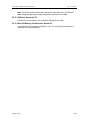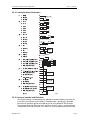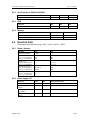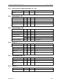
1
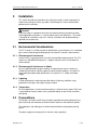
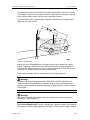
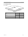
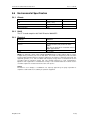
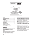
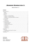
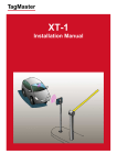
MANUAL
XT-3 Reader
Installation Manual & Data Sheet
Doc no. 11-267 02
© TagMaster NA
XT-3 Reader Installation Manual & Data Sheet
Revision
01
02
Date
2011-08-23
2011-12-08
Doc no. 11-267 02
Comment
First version
Additional info added during product safety
assessment
Copyright
The copyright and ownership of this document belongs to TagMaster NA. The document may be
downloaded or copied provided that all copies contain the full information from the complete document. All
other copying requires a written approval from TagMaster NA.
Disclaimer
While effort has been taken to ensure the accuracy of the information in this document TagMaster N A
assumes no responsibility for any errors or omissions, or for damages resulting from the use of the
information contained herein. The information in this document is subject to change without notice.
© TagMaster NA
2 (28)
XT-3 Reader Installation Manual & Data Sheet
Doc no. 11-267 02
Table of Contents
1
Introduction
4
1.1
XT-3 Reader ................................................................................................. 4
1.2
TagMaster’s RFID System ............................................................................ 4
2
Safety Instructions
5
2.1
Instructions ................................................................................................... 5
2.2
Warnings ...................................................................................................... 5
3
Installation
6
3.1
Environmental Considerations ...................................................................... 6
3.2
Preconditions ................................................................................................ 6
3.3
Mounting the Reader .................................................................................... 7
3.4
Mounting the External Antenna (Optional) .................................................... 9
3.5
Cable Connections...................................................................................... 10
3.6
Identifying Readers across TCP/IP Networks.............................................. 11
4
Testing
12
4.1
Installation Test........................................................................................... 12
4.2
Trouble Shooting ........................................................................................ 13
5
Technical Data
14
5.1
Reader Overview ........................................................................................ 14
5.2
Interfaces.................................................................................................... 15
5.3
Performance Data....................................................................................... 22
5.4
Electrical Data............................................................................................. 23
5.5
Mechanical Data ......................................................................................... 25
5.6
Environmental Specification........................................................................ 27
6
Contact
28
6.1
Technical Support ....................................................................................... 28
6.2
Office .......................................................................................................... 28
© TagMaster NA
3 (28)
XT-3 Reader Installation Manual & Data Sheet
1
Introduction
1.1
XT-3 Reader
Doc no. 11-267 02
The XT-3 RFID reader is a full functionality EPC Gen 2 (ISO 18000-6C) reader for
access installations such as Parking, Gated Communities and Condominiums. The
reader is available in two models: XT-3 eu for the European market (865.6-867.6 MHz)
and XT-3 us for the US market (902-928 MHz). The reader has a built-in antenna and
can be expanded with an optional external antenna. The read range is five meters for
XT-3 eu and six meters for XT-3 us.
The XT-3 Reader can work as a standalone reader when using ACTS. The Readers
are equipped with all TagMaster reader application software providing suitable
functionality. ACTS (Access Control and Tracking System) software can be embedded
on the reader for standalone operation.
The reader can be configured and controlled via the Ethernet interface, either locally or
remotely via an Internet connection. The XT-3 Reader supports several standard
interfaces including Ethernet (TCP/IP), RS232, RS485 and Wiegand/Mag-stripe.
More detailed information about the reader’s functionality is available in 06-118, “GEN4
Reader User’s Manual”.
1.2
TagMaster’s RFID System
TagMaster’s RFID system consists of readers and ID-tags. Readers can work
standalone or be connected to a host computer using serial or Ethernet interfaces.
1.2.1
Reader
The reader is a device for reading ID-tags using radio frequency. Some readers have
the capability to write information to ID-tags that support this.
The reader has a built-in antenna for communication with ID-tags. Some readers can
be expanded with external antennas. The reader also has various interfaces for
communication with a host computer and other external devices. When an acceptable
ID-tag is read, the reader can for example pull a relay connected to a barrier and grant
access to a vehicle and at the same time sound the buzzer and flash the visible
indicator.
To reduce the risk of interference, several readers in close proximity to each other
should use frequency hopping or be set to different frequency channels.
1.2.2
ID-tags
An ID-tag carries information that can be read at a long distance using radio frequency.
TagMaster has a range of ID-tags with different properties. Technical data for the
different ID-tags are presented in the respective ID-tag’s data sheet.
© TagMaster NA
4 (28)
XT-3 Reader Installation Manual & Data Sheet
2
Safety Instructions
2.1
Instructions
Doc no. 11-267 02
Read this manual carefully before using the XT-3 reader and take notice of warnings in
order to prevent injury and product damage.
Where local regulations exist, these are to be followed. The safety information in this
manual is a supplement to local regulations. It is the responsibility of the local project
manager to make certain that local regulations are known and followed.
The relevant manual (including this safety information) must be followed in any work
performed on the TagMaster products or systems.
The use of TagMaster’s genuine spare parts and accessories are recommended.
TagMaster will not assume responsibility for any malfunction due to use of spare parts
or accessories produced by a third party.
2.2
Warnings
Warnings are used throughout this manual to alert the reader to special instructions
concerning a particular task or operation that may be hazardous if performed
incorrectly or carelessly. The warnings are preceded by the common hazard symbol.
Figure 1 Hazard Symbol
The following two levels of warnings are used:
Warning!
Warning means that an accident may occur if the safety precautions are neglected.
This type of accident may cause injury. It may also damage the product.
Caution!
Caution means that an accident may occur if the safety precautions are neglected. This
type of accident may damage the product.
© TagMaster NA
5 (28)
XT-3 Reader Installation Manual & Data Sheet
3
Doc no. 11-267 02
Installation
This section describes the procedure of installing the reader, including mounting the
reader and installing the necessary cables. Read through this entire section before
performing the installation.
Caution!
Install the reader in accordance with local and national building and electrical codes
and/or applicable jurisdictions i.e. state or federal laws or city ordinances. The reader
is designed for installation using Class 2 wiring. Installation shall be performed by a
qualified service technician.
3.1
Environmental Considerations
The XT-3 reader is a reliable solution for identification systems because it is unaffected
by the normal electromagnetic background noise found in industries and elsewhere.
3.1.1
Electromagnetic Interference
Industrial noise is typically present in the kHz and low MHz frequency band. The XT-3
reader uses 860-960 MHz frequencies, so typical industrial noise will not affect the
communication.
3.1.2
Electromagnetic Interference in Cables
By using specified cables, proper shielding, and grounding as well as selecting a
suitable communication interface, optimum communication reliability is ensured. For
more information about cable specifications see section 3.2.2, “Cables and Power
Supply”.
3.1.3
Lightning
In order to protect the reader from possible effects of lightning, additional surge
protection on the inputs and outputs may be needed.
3.1.4
Temperature
For most applications, normal convection cooling is sufficient for the reader. But if heat
is generated close to the reader, the use of forced cooling or heat shields should be
considered.
3.2
Preconditions
The locations of readers and ID-tags have been specified during the project planning
phase, based on considerations of communication distances and movement speeds.
The cable paths and cable types have been determined during the project planning
phase.
The power supply must comply with all relevant safety regulations.
© TagMaster NA
6 (28)
XT-3 Reader Installation Manual & Data Sheet
Doc no. 11-267 02
The equipment must be disconnected from all voltage sources before any installation
or service work is carried out. Capacitors inside the equipment can hold their charge
even if the equipment has been disconnected from all voltage sources.
Caution!
Damage may be the result if the equipment is switched on when parts are removed
from the controller board, or if a PCB is removed within one minute after switching off
the equipment.
3.2.1
Tools
The following tools are necessary for installation:
•
•
•
•
•
•
3.2.2
Adjustable spanner
Screwdriver, Torx T20
Screwdriver, Philips PH00x60 or SZS 0,4x2,5
Side cutter
Wire stripper
Crimping tool for ferrules
Cables and Power Supply
Cables and power supply are not supplied with the XT-3 reader.
All cables should be shielded and suitable for the installation environment, for instance
indoor or outdoor environment. Use flexible cables with stranded wire. The reader
chassis should be grounded during installation. This is done using the ground screw
(position 12 in Figure 4 Overview of the reader with open lid). As an alternative a
metallic cable gland can also be used to connect to the reader chassis to ground using
the power cable shielding.
The terminal blocks used are Phoenix, type PT 1.5, which allow for a cable area of 0.2
to 1.5 mm² (AWG 26-14). Stranded wires must be fitted with a ferrule before being
inserted in the termination blocks.
The cable for the RS485 interface must be a twisted pair cable and conform to the EIA
RS485 standard. When using RS485 communication, correct termination of the
interface must always be considered in order to handle transmission-line effects. The
Reader has no built-in RS-485 termination as the termination points depends on the
number of transceivers in the network.
A category 5 (CAT5e) cable is required for the Ethernet connection.
The reader shall be powered by a UL Listed or Certified, Class 2 or LPS power supply
suitable for outdoor use, rated 24 V DC, 1 A minimum. The power supply shall fulfil the
specifications in section 5.4.2, “Power supply, J31”.
3.3
Mounting the Reader
Mount the reader in a horizontal position with the cable glands on the bottom side.
Direct the reader so that the reading lobe covers the positions of the ID-tags.
© TagMaster NA
7 (28)
XT-3 Reader Installation Manual & Data Sheet
Doc no. 11-267 02
For optimal performance, tilt and rotate the reader into a position so that the front side
of the reader is parallel with the front side of the ID-tag to be read. Align the reader so
that the actual reading range is 60–70% of the specified maximum.
The figure below shows a typical reader installation. Note that the installation details
depend on site requirements.
=
60
- 7
0%
10
0
%
=
TM00103
Figure 2 Reading lobe
How to mount the ID-tag depends on the type of tag and which object that is being
tagged. TagMaster’s windshield ID-tag should be mounted in a horizontal position in
the windshield. Note that some cars have a metallized windshield. The ID-tag must be
mounted in an area of the windshield without metallization.’
Never mount the reader close to, and directly facing, a large metal area.
Warning!
To comply with Council Recommendation 1999/519/EC and FCC regulations, this
reader must be installed to provide a separation distance of at least 20 cm from all
persons and must not be co-located or operating in conjunction with any other antenna
or transmitter.
Warning!
Hot surface! The back of the reader enclosure can become hot during continuous
operation in a hot environment.
The Universal Mounting Kit (Part No. 193600) from TagMaster enables the Reader to
be mounted in a wide variety of positions and angles. The kit contains all parts needed
© TagMaster NA
8 (28)
XT-3 Reader Installation Manual & Data Sheet
Doc no. 11-267 02
for mounting the Reader on a wall or on a pole. The Universal Mounting Kit is suitable
for outdoor use. See separate data sheet for more details.
Figure 3 XT-3 reader mounted on a pole with Universal Mounting Kit
Mounting hole layout details are available in section 5.5.2, “Dimensions”.
Note: Do not drill any additional holes in the enclosure, as that would affect the sealing
specification.
Caution!
Never exceed the environmental and electrical limits specified in section 5, “Technical
Data”. Exceeding the limits can result in permanent damage to the reader.
3.4
Mounting the External Antenna (Optional)
The optional external antenna has the same physical dimensions and RF performance
as the reader and should be mounted in the same way as the reader (see section 3.3,
“Mounting the Reader”).
Different reader models require different external antennas:
Model
Part No.
163100
External XT-3 eu antenna
163200
External XT-3 us antenna
© TagMaster NA
9 (28)
XT-3 Reader Installation Manual & Data Sheet
Doc no. 11-267 02
Connect the external antenna to the reader using an RF cable with RP-TNC
connectors. Cables supplied by TagMaster are tuned to give maximum performance
while still being within the regulatory limits.
The external antenna also has built in LEDs. These can be controlled from the XT-3 by
connecting an optional M12-4 cable between the reader and the external antenna.
The following cables are available:
Model
Part No.
196025
Antenna RF-cable 2.5 m
196050
Antenna RF-cable 5.0 m
196125
Antenna LED-cable 2.5 m
196150
Antenna LED-cable 5.0 m
3.5
Cable Connections
Three available openings (20mm, 16 mm and 16 mm) in the base are sealed with blind
plugs and can be used for cable connections. The XT-3 reader is delivered with one
M20 cable gland for incoming cables and is also delivered with two cable gland options
for incoming cables. Using these options it is possible to handle one or two separate
cables in the same single gland. The alternatives are 1 x 6-12 mm or 2 x 4-6 mm. This
makes it possible if for instance using TCP/IP, to have a separate shielded CAT5e
cable for communication, while still having two other shielded cables for power and
possible I/O connections.
Connect cables as described below.
1.
2.
3.
4.
5.
6.
Open the reader.
Cut the cable to a suitable length and pull it through the cable gland.
Measure enough length of the cable to reach to the terminal blocks.
Strip the outer insulation of the cable inside the reader.
Tighten the cable gland around the cable.
Strip the ends of the conductors and crimp a ferrule onto the stripped end of
each conductor.
7. Connect the conductors to the corresponding terminal blocks.
All screw terminals and connectors are documented in section 5.2, “Interfaces”. The
torque to be used when fastening the lid to the base of the reader using the 8 screws
should be 1.0 Nm. First use preset torque, then tighten opposite screws in pairs.
Caution!
Never disconnect the internal or external antenna cable during operation; doing so will
damage the reader! Never operate the reader close to, and directly facing a metal surface;
dosing so may damage the reader!
Caution!
Do not remove the pressure balance membrane; it will compromise the IP classification.
© TagMaster NA
10 (28)
XT-3 Reader Installation Manual & Data Sheet
3.6
Doc no. 11-267 02
Identifying Readers across TCP/IP Networks
If using a TCP/IP connection to the reader, the XT-3 can be identified across the
network using the unique MAC address found on the option label of the unit.
© TagMaster NA
11 (28)
XT-3 Reader Installation Manual & Data Sheet
4
Testing
4.1
Installation Test
Doc no. 11-267 02
After having completed the installation as described in previous section, carry out an
installation inspection and verification. If an error occurs, the guidelines in section 4.2,
“Trouble Shooting”, may be valuable.
4.1.1
Inspection
Ensure that there are no metal objects between or close to the reader and the ID-tag in
the positions where communication is to take place.
Ensure that the reader and the ID-tag are aligned properly. Avoid communication at
maximum specified distance and misalignment.
Ensure that the reader is not placed in a location where it is exposed to excessive heat
or electromagnetic interference.
4.1.2
Verification
Power up the reader and verify that it beeps once.
If the hardware fails to initiate, the reader will make two more attempts to initiate it.
Each attempt is indicated by a short beep. If the hardware does not initiate after three
attempts the reader will not read tags. See section 4.2, “Trouble Shooting” for more
information.
Verify that the reader reads ID-tags and that the read lobe covers the required area. If
specific reader application software is used, consult the corresponding software
manual for more information concerning installation test.
© TagMaster NA
12 (28)
XT-3 Reader Installation Manual & Data Sheet
4.2
Doc no. 11-267 02
Trouble Shooting
Caution!
If the reader malfunctions, contact TagMaster Technical Support (see section 6,
“Contact” for details). Never try to dismantle any components inside the reader, since
there are no user serviceable parts inside the reader. Any unauthorized alterations to
the reader will invalidate the warranty.
Three system status indicators on the controller board inside the reader show the
status of the unit (see section 5.1, “Reader Overview” for information on placement).
The table below explains the meaning of the different indicators.
Table 1 System status indicators
Colour
Yellow
Green
Red
Mode
Indicates
On
Power on
Off
Power off
Flashing
System SW running
Initially on
System SW loading
Persistently on/off
System SW fault
Flashing
HW initiated and running
On
Initiation process
Off
HW not initiated
The following table describes the most common problems encountered during
installation and proposed solutions.
Table 2 Most common problems
Problem
Solution
Yellow system status
indicator is off
Check the power supply.
Green system status
indicator is on or off
Switch off the power supply, switch it on again, and
wait 30 seconds. This can be done by pulling the J31
terminal block off the board and putting it back again.
If the reader fails to start again, contact TagMaster
support.
Red system status indicator
is on or off
Switch off the power supply and switch it on again.
This can be done by pulling the J31 terminal block off
the board and putting it back again. If the reader fails
to start again, contact TagMaster support.
© TagMaster NA
13 (28)
XT-3 Reader Installation Manual & Data Sheet
5
Technical Data
5.1
Reader Overview
Doc no. 11-267 02
Figure 4 shows an overview of a TagMaster XT-3 reader with open lid.
1
2
3
4
5
6
14
13
12
7
8
9
11
10
Figure 4 Overview of the reader with open lid
The following table describes the position of the components inside the reader.
No
Component
No
Component
1
Controller board
8
External antenna RF connector
2
Visible indicator
9
External antenna LED connector (M12-4)
3
Buzzer
10
Cable gland opening
4
Red system status indicator
11
Terminal blocks
5
Green system status indicator
12
Ground M3
6
Yellow system status indicator
13
Ethernet connector
7
Enclosure base
14
USB connector
© TagMaster NA
14 (28)
XT-3 Reader Installation Manual & Data Sheet
5.2
Interfaces
5.2.1
Connector Overview
Doc no. 11-267 02
For easy installation and service the cables are screwed into removable block
connectors.
P2
P1
P3
123 12345612345 123412 1234
J1
J51
J52
J31 J32 J2
12345123 123
J41 J42 J43
TM00107
Figure 5 Connector overview
Note: It is possible to attach or remove the terminal block connectors inside the reader
for more convenient connection of the cables.
The terminals are grouped as specified in the sections below.
5.2.2
Relay Output, Group J1
The controller board has one relay output.
Table 3 Relay Output, Group J1
5.2.3
Pin
Signal
Description
1
RCOM
Common terminal
2
ROPEN
Connected to RCOM when relay is open
3
RCLOSE
Connected to RCOM when relay is closed
Wiegand/Mag-stripe, Group J2
The controller board has an access control interface that supports both Wiegand and
Mag-stripe protocols.
© TagMaster NA
15 (28)
XT-3 Reader Installation Manual & Data Sheet
Doc no. 11-267 02
5.2.3.1 Wiegand Interface
Table 4 Wiegand, Group J2
Pin
Signal
Description
1
D0
Wiegand 0 (zero) signal
2
D1
Wiegand 1 signal
3
CL
Card load signal
4
GND
Ground
5.2.3.2 Wiegand Timing
The following values apply when all outputs are pulled up to 5V with 1kΩ resistors.
Table 5 Wiegand interface timing
Symbol
Parameter
tSU
CL to D# setup time
tF
Fall time (all signals)
125
ns
tR
Rise time (all signals)
5
µs
tPI
Pulse interval
2
ms
tPW
Pulse width
80
µs
tH
CL hold time after last D# change
Min
Typ
Max
Unit
0
tPI
tSU
D0
D1
tPW
µs
tH
tR
≈
tF
0
≈ ≈
CL
µs
Figure 6 Wiegand timing diagram
5.2.3.3 Mag-stripe Interface
Table 6 Mag-stripe, Group J2
Pin
Signal
Description
1
CLK
Mag-stripe clock signal
2
DATA
Mag-stripe data signal
3
LOAD
Card load signal
4
GND
Ground
© TagMaster NA
16 (28)
XT-3 Reader Installation Manual & Data Sheet
Doc no. 11-267 02
5.2.3.4 Mag-stripe Timing
The following values apply when all outputs are pulled up to 5V with 1kΩ resistors.
Table 7 Mag-stripe interface timing
Symbol
Parameter
tSU
LOAD to CLK setup time
tF
Fall time (all signals)
125
ns
tR
Rise time (all signals)
5
µs
tCL
Clock low
150
µs
tCH
Clock high
150
µs
tH
LOAD hold time after last CLK change
Min
Typ
Max
Unit
0
0
µs
≈
LOAD
µs
tSU
tCL
tF
tH
≈
CLK
tR
tCH
tDH
≈
DATA
Figure 7 Mag-stripe timing diagram
5.2.4
Power Supply, Group J31
Pin 1 is internally connected to pin 3 and pin 2 is internally connected to pin 4. The
purpose is to make it possible to feed power to any peripheral equipment. Use pins 1
and 2 for power supply connection.
Table 8 Power Supply, Group J31
5.2.5
Pin
Signal
Description
1
SPL
Positive DC supply input
2
RTN SPL
Negative DC supply input
3
SPL
Positive DC supply input, internally connected to pin 1
4
RTN SPL
Negative DC supply input, internally connected to pin 2
Not used, Group J32
This group is not used.
5.2.6
RS485 Serial Communication Interface, Group J41
The controller board has one RS485 serial interface for both 2-wire and 4-wire
communication. RS485 supports multi-drop serial networks. The communication can
be in both full duplex (4-wire) and half duplex (2-wire).
Note: If the installation requires long cables or high data speeds it may be necessary to
use termination.
© TagMaster NA
17 (28)
XT-3 Reader Installation Manual & Data Sheet
Doc no. 11-267 02
Table 9 Full Duplex (4-wire) RS485 Serial Communication Interface, Group J41
Pin
Signal
Description
1
TX+
Transmitted data, from reader to host
2
TX−
3
GND
Ground
4
RX+
Received data, to reader from host
5
RX−
Table 10 Half Duplex (2-wire) RS485 Serial Communication Interface, Group J41
5.2.7
Pin
Signal
Description
1
TX/RX+
Transmitted and received data, to and from Host
2
TX/RX−
3
GND
Ground
4
NC
Not used
5
NC
RS232 Serial Communication Interface, Group J42
The controller board has one RS232 serial interface.
Table 11 RS232 serial communication interface, Group J42
5.2.8
Pin
Signal
Description
1
TX
Transmitted data, from reader to host
2
RX
Received data, to reader from host
3
GND
Ground
Service Interface, Group J43
The service interface is used for maintenance and configuration of the reader. Do not
use the service interface as a regular system interface.
Table 12 Service Interface, Group J43
Pin
Signal
Description
1
TX
Transmitted data, from reader to host
2
RX
Received data, to reader from host
3
GND
Ground
© TagMaster NA
18 (28)
XT-3 Reader Installation Manual & Data Sheet
Doc no. 11-267 02
A cable for connecting the service interface to a 9-pin PC COM port should be created
as specified in Table 13.
Table 13 Cable specification: PC COM port ↔ Reader Service Interface
9-pin D-sub Connector
(female on cable)
5.2.9
Reader Connector
Pin
Signal
Pin
Signal
2
RXD
1
TX
3
TXD
2
RX
5
GND
3
GND
Isolated Inputs, Group J51
The reader has three isolated optocoupler inputs which are protected from noisy
environments.
Table 14 Isolated Inputs, Group J51
Pin
Signal
Description
1
IN 1A
Input signal 1
2
IN 1C
Input reference 1
3
IN 2A
Input signal 2
4
IN 2C
Input reference 2
5
IN 3A
Input signal 3
6
IN 3C
Input reference 3
5.2.10 Isolated Outputs, Group J52
This group is in the XT-3 pre-configured with cables to power (J31) and an M12-4
connector in the chassis to support the LEDs of the external antenna. If required the
pre-configuration can be removed and the group used for other purposes.
The group consists of two open collector outputs.
Table 15 Isolated Outputs, Group J52
Pin
Signal
Description
1
OUT 1C
Output 1 collector
2
OUT 1E
Output 1 emitter
3
OUT SPL
External supply voltage for the outputs
4
OUT 2C
Output 2 collector
5
OUT 2E
Output 2 emitter
5.2.11 Ethernet, Connector P1
An RJ45 connector labelled P1, with two internal indicators, is provided for Ethernet
connection. The clip for detaching the cable faces upwards from the controller board
surface to allow mid-board mounts. The Ethernet connector has eight pins and the wire
scheme is based on the T568A standard.
© TagMaster NA
19 (28)
XT-3 Reader Installation Manual & Data Sheet
Doc no. 11-267 02
Note: The RJ45 connector will not pass through the cable gland. Pass the Ethernet
cable through the cable gland, before crimping the connector on the cable.
5.2.12 USB Host, Connector P2
USB devices are connected using a standard USB type A connector.
5.2.13 Micro SD Memory Card Interface, Socket P3
A standard micro SD memory card socket is used. The card socket is placed on the
underside of the controller board.
© TagMaster NA
20 (28)
XT-3 Reader Installation Manual & Data Sheet
Doc no. 11-267 02
5.2.14 Internal Interface Schematics
J1:
1
RCOM
2
ROPEN
3
RCLOSE
Relay Inactive
J51: 1
IN 1A
2
IN 1C
3
IN 2A
4
IN 2C
5
IN 3A
6
IN 3C
J52: 1
OUT 1C
2
OUT 1E
3
OUT SPL
4
OUT 2C
5
OUT 2E
J31: 1
SPL
2
RTN SPL
3
SPL
4
RTN SPL
+
1k
+
1k
+
1k
3k3
6k8
+
10k
10k
+
+
DC/DC
Lid Off
J32: 1
TAMP A
2
TAMP B
1
D0/CLK (Wiegand/Mag-stripe)
2
D1/Data (Wiegand/Mag-stripe)
1k
3
CL/Load (Wiegand/Mag-stripe)
1k
4
GND (Signal Reference)
1k
J2:
220
220
220
J41: 1
TX+/RX+ (RS485 4-wire/2-wire)
2
3
GND (Signal Reference)
4
RX+ (RS485 4-wire)
Standard IC
5
J42: 1
TX (RS232)
2
RX (RS232)
3
GND (Signal Reference)
Standard IC
J43: 1
TX (RS232 Service Interface)
2
RX (RS232 Service Interface)
3
GND (Signal Reference)
Standard IC
10M
Chassis
06-234 01
5.2.15 Interface Isolation and Protection
The hardware design is protected against radiated or wired disturbances by extensive
use of filters, transformers and shielding. The power input is galvanically separated
from the main electronic part of the reader by use of an on-board DC-DC converter.
The Interface Block with Ethernet, Serial Interfaces and I/O signals is also galvanically
isolated from the rest of the reader. This makes sure that no ground currents will occur
© TagMaster NA
21 (28)
XT-3 Reader Installation Manual & Data Sheet
Doc no. 11-267 02
between shielding, power lines or other interfaces. The common GND connection in J2
and J41-J43 is a floating reference ground for the interface block signals. This makes it
possible to operate the interface with the voltage potential set from the other party. The
reference ground is internally connected to the chassis via a discharge resistor to avoid
static voltage potential. It has no other reference to connections outside the interface
block.
The USB port GND is connected to the chassis.
The Wiegand/Mag-stripe interface, the Isolated Inputs, and Isolated Outputs have a
varistor protection that will short-circuit signals over rated maximum 30 V.
Shielded Cable
Shielded Cable
Reader Electronics
Isolated I/O
Isolated
Optoisolated
DC/DC Converter
Interface Block
06-237 01
Figure 8 Figure shows the principal galvanic isolation
5.3
Performance Data
5.3.1
Communication range data
Note: Read and write ranges depend on tag-model and physical environment!
5.3.1.1 XT-3 eu
Parameter
Value
Unit
Read range
5
m
16
Ft
4
M
13
Ft
Parameter
Value
Unit
Read range
6
m
20
ft
5
m
16
ft
Write range
5.3.1.2 XT-3 us
Write range
© TagMaster NA
22 (28)
XT-3 Reader Installation Manual & Data Sheet
5.3.2
5.3.3
Doc no. 11-267 02
Serial interfaces RS232 and RS485
Parameter
Min
Max
Unit
Baud Rate
1.2
115.2
kb/s
Min
Max
Unit
12
Mb/s
USB
Parameter
Data Rate
5.3.4
5.4
Memory
Parameter
Value
Unit
Flash Memory Size
16
MByte
RAM Memory Size
32
MByte
Electrical Data
Data regards the temperature range −40°C ( -40°F) to +60°C ( +140°F).
5.4.1
5.4.2
Radio / Antenna
Parameter
Value
Unit
Antenna Polarisation
Circular
Antenna Gain
XT-3 eu / ext. antenna eu
XT-3 us / ext. antenna us
≤6.5
≤6.0
dBi
dBi
Output Power:
XT-3 eu / ext. antenna eu
XT-3 us / ext. antenna us
2
4
W (e.r.p)
W (e.i.r.p)
Operating Frequencies
XT-3 eu / ext. antenna eu
XT-3 us / ext. antenna us
865.6-867.6
902-928
MHz
MHz
Beamwidth
XT-3 eu / ext. antenna eu
XT-3 us / ext. antenna us
70
70
°
°
Power supply, J31
Parameter
Value
Unit
Measured between pin
DC Power Supply
10–30
V
1-2, 3-4
DC Power Consumption
Typical
8.8
W
1-2, 3-4
Max DC Power
Consumption
15
W
1-2, 3-4
Isolation to Shielding and
Chassis
1500
V
1…6 to chassis
© TagMaster NA
23 (28)
XT-3 Reader Installation Manual & Data Sheet
5.4.3
5.4.4
5.4.5
Serial interfaces RS232 and RS485, J41 – J43
Parameter
Min
Isolation to Shielding and
Chassis
1500
V
Min
Max
Unit
Measured between pins
High Voltage (active)
2.4
30
V
1-2, 3-4, 5-6
Low Voltage(inactive)
0
0.2
V
1-2, 3-4, 5-6
Input Impedance
1000
Ohm
1-2, 3-4, 5-6
Isolation to Shielding and
Chassis
1500
V
1…6 to chassis
Isolated outputs, J52
Parameter
Min
Max
Unit
Measured between pins
Applied Voltage Out 1,2
1
30
V
1-2, 4-5
Sink Current Out 1
0
500
mA
1-2
Sink Current Out 2
0
100
mA
4-5
12
30
V
3-2, 3-5
3
9
mA
3-2, 3-5
V
1…5 to chassis
Max
Unit
Measured between pins
Switch Current
2
A
1-2, 1-3
Switch Voltage DC
60
V
1-2, 1-3
Switch Voltage AC
30
Vrms
1-2, 1-3
Switch Power
50
W
1-2, 1-3
V
1…3 to chassis
Max
Unit
Measured between pins
30
V
1-4, 2-4, 3-4
50
mA
1-4, 2-4, 3-4
V
1…4 to chassis
1500
Relay, J1
Parameter
Isolation to Shielding and
Chassis
Min
1500
Wiegand/Mag-stripe, J2
Parameter
Min
Voltage
Sink Current
Isolation to Shielding and
Chassis
5.4.8
Unit
Parameter
Isolation to Shielding
5.4.7
Max
Isolated inputs, J51
Supply
5.4.6
Doc no. 11-267 02
1500
USB, P2
Parameter
Total Current Supply
© TagMaster NA
Min
Max
Unit
500
mA
24 (28)
XT-3 Reader Installation Manual & Data Sheet
5.5
Mechanical Data
5.5.1
General
Parameter
Weight
Dimensions
Doc no. 11-267 02
Value
Unit
2.3
kg
5.1
lbs
300 x 300 x 60
mm
11.8 x 11.8 x 2.4
in
Lid Material
Plastic
Base Material
Aluminium
Sealing
Rubber Gaskets
© TagMaster NA
25 (28)
XT-3 Reader Installation Manual & Data Sheet
Dimensions
16,2
20,2
16,2
13
300
100
75
60
16,2
12
5.5.2
Doc no. 11-267 02
75
100
300
© TagMaster NA
26 (28)
XT-3 Reader Installation Manual & Data Sheet
Doc no. 11-267 02
5.6
Environmental Specification
5.6.1
Climate
5.6.2
Parameter
Value
Cold
−40°C (−40°F)
Heat
+60°C (+140°F)
Ingress Protection
IP66
Reference
-
-
RoHS
The XT-3 reader complies with RoHS Directive 2002/95/EC
5.6.3
Electrical
Parameter
Reference
Immunity
CE: EN 301 489-3
Emission
CE: EN 302 208-2 (radio) and EN 301 489-3
(EMC).
FCC: Part 15 subpart B. The reader fulfils Class A
digital equipment limits
Safety
EN 60 950-1
NOTE: This equipment contains module FCCID: QV5MERCURY5E. It complies with the limits for a Class
A digital device, pursuant to part 15 of the FCC Rules. These limits are designed to provide reasonable
protection against harmful interference when the equipment is operated in a commercial environment. This
equipment generates, uses, and can radiate radio frequency energy and, if not installed and used in
accordance with the instruction manual, may cause harmful interference to radio communications.
Operation of this equipment in a residential area is likely to cause harmful interference in which case the
user will be required to correct the interference at his own expense.
Caution
Information to user: Changes or modifications not expressly approved by the party responsible for
compliance could void the user’s authority to operate the equipment.
© TagMaster NA
27 (28)
XT-3 Reader Installation Manual & Data Sheet
6
Doc no. 11-267 02
Contact
For any further inquiries, please contact TagMaster North America, Inc.
6.1
Technical Support
Phone: 253.238.1421
Fax: 253.238.7762
E-mail: [email protected]
6.2
Office
TagMaster North America, Inc.
2007A 70th Avenue West
Tacoma,WA 98466
Phone: 253.238.1421
Fax: 253.238.7762
E-mail: [email protected]
Web: www.tagmasterna.com
© TagMaster NA
28 (28)