1
Allen-Bradley
PanelBuilder1400e
Configuration
Software for
Windows
(Cat. No. 2711E–ND1)
Getting
Started
Important User
Information
Because of the variety of uses for the products described in this
publication, those responsible for the application and use of this
control equipment must satisfy themselves that all necessary steps
have been taken to assure that each application and use meets all
performance and safety requirements, including any applicable laws,
regulations, codes, and standards.
The illustrations, charts, sample programs, and layout examples
shown in this guide are intended solely for purposes of example.
Since there are many variables and requirements associated with any
particular installation, Allen-Bradley does not assume responsibility
or liability (to include intellectual property liability) for actual use
based upon the examples shown in this publication.
Allen-Bradley publication SGI-1.1, Safety Guidelines for the
Application, Installation, and Maintenance of Solid-State Control
(available from your local Allen-Bradley office), describes some
important differences between solid-state equipment and
electromechanical devices that should be taken into consideration
when applying products such as those described in this publication.
Reproduction of the contents of this copyrighted publication, in
whole or in part, without written permission of Allen-Bradley
Company, Inc., is prohibited.
Throughout this manual we use notes to make you aware of safety
considerations:
!
ATTENTION: Identifies information about practices
or circumstances that can lead to personal injury or
death, property damage, or economic loss.
Attention statements help you to:
• identify a hazard
• avoid the hazard
• recognize the consequences
Important:
Identifies information that is critical for successful
application and understanding of the product.
PanelBuilder, PanelView, Data Highway Plus, DH+, ControlNet, and SLC are trademarks, and
PLC, PLC-2, and PLC-3 are registered trademarks of Allen-Bradley Company, Inc.
RSView and RSLinx are trademarks of Rockwell Software Inc.
IBM, PC, PS/2, VGA, and PC-DOS are registered trademarks of International Business Machines
Corporation.
Epson is a registered trademark of Seiko Epson Corporation.
Ethernet is a registered trademark of Digital Equipment Corporation, Intel, and Xerox
Corporation.
Microsoft, Windows, MS, and MS-DOS are registered trademarks of Microsoft Corporation.
Mouse Systems is a trademark of MSC Technologies, Inc.
AutoCAD is a registered trademark of Autodesk Inc.
Taylor, and ProWORXPLUS are registered trademarks of Taylor Industrial Software, Inc.
MODICON, MODSOFT, Quantum, and Modbus are registered trademarks of
AEG Schneider Automation, Inc.
All other brand and product names are trademarks of their respective companies
and are hereby acknowledged.
Preface
Welcome to PanelBuilder 1400e Configuration Software for Windows
Registering Your Copy of PanelBuilder 1400e . . . . . . . . . . . . . . . .
Available Documentation . . . . . . . . . . . . . . . . . . . . . . . . . . . . . . .
What’s in Getting Started? . . . . . . . . . . . . . . . . . . . . . . . . . . . . . .
Preface . . . . . . . . . . . . . . . . . . . . . . . . . . . . . . . . . . . . . . . . . .
Chapter 1, Introducing PanelBuilder 1400e . . . . . . . . . . . . . . . .
Chapter 2, Setting Up PanelBuilder 1400e . . . . . . . . . . . . . . . . .
Chapter 3, A Brief Tour of PanelBuilder 1400e . . . . . . . . . . . . . .
Chapters 4 to 9, The Tutorial . . . . . . . . . . . . . . . . . . . . . . . . . . .
Who Should Read Getting Started? . . . . . . . . . . . . . . . . . . . .
Terminology . . . . . . . . . . . . . . . . . . . . . . . . . . . . . . . . . . . . . . . .
Conventions Used . . . . . . . . . . . . . . . . . . . . . . . . . . . . . . . . . . . .
Mouse Conventions . . . . . . . . . . . . . . . . . . . . . . . . . . . . . . . . .
Selection Conventions . . . . . . . . . . . . . . . . . . . . . . . . . . . . . . .
Selection Conventions in Dialog Boxes . . . . . . . . . . . . . . . . .
Key Conventions . . . . . . . . . . . . . . . . . . . . . . . . . . . . . . . . . . .
Command Conventions . . . . . . . . . . . . . . . . . . . . . . . . . . . . . .
Before You Begin . . . . . . . . . . . . . . . . . . . . . . . . . . . . . . . . . . . . .
Technical Support Services . . . . . . . . . . . . . . . . . . . . . . . . . . . . . .
Introducing PanelBuilder
1400e
P–1
P–1
P–1
P–2
P–2
P–2
P–3
P–3
P–3
P–3
P–4
P–4
P–4
P–4
P–5
P–5
P–5
P–6
P–6
Chapter 1
About PanelBuilder 1400e . . . . . . . . . . . . . . . . . . . . . . . . . . . . . .
PanelBuilder, PanelView Terminals, and the PLC . . . . . . . . . . . . . .
PanelBuilder 1400e . . . . . . . . . . . . . . . . . . . . . . . . . . . . . . . . .
PanelView Operator Terminals . . . . . . . . . . . . . . . . . . . . . . . . .
Programmable Logic Controller . . . . . . . . . . . . . . . . . . . . . . . . .
Understanding the Different Network Types . . . . . . . . . . . . . . . .
What’s New in PanelBuilder . . . . . . . . . . . . . . . . . . . . . . . . . . . . .
1400e, Version 4 . . . . . . . . . . . . . . . . . . . . . . . . . . . . . . . . . . . . .
Windows NT Compatibility . . . . . . . . . . . . . . . . . . . . . . . . . . . .
ControlNet Station Addressing . . . . . . . . . . . . . . . . . . . . . . . . .
Ethernet Pass-Through . . . . . . . . . . . . . . . . . . . . . . . . . . . . . .
CD-ROM Installation . . . . . . . . . . . . . . . . . . . . . . . . . . . . . . . .
RSLinx Communication Drivers . . . . . . . . . . . . . . . . . . . . . . . . .
1–1
1–1
1–2
1–2
1–4
1–5
1–8
1–8
1–8
1–8
1–8
1–9
1–9
Publication 2711E-818 – January 1998
toc–ii
Table of Contents
Setting Up PanelBuilder
1400e
A Brief Tour of PanelBuilder
1400e
Publication 2711E-818 – January 1998
Chapter 2
Requirements for Running PanelBuilder . . . . . . . . . . . . . . . . . . . .
Application File Transfer Equipment . . . . . . . . . . . . . . . . . . . . .
PanelView Terminal Requirements for Running PanelBuilder 1400e
Applications . . . . . . . . . . . . . . . . . . . . . . . . . . . . . . . . . . . .
CD-ROM Install . . . . . . . . . . . . . . . . . . . . . . . . . . . . . . . . . . . . . .
Installing PanelBuilder 1400e Version 4 from CD-ROM on Windows NT
or Windows 95 . . . . . . . . . . . . . . . . . . . . . . . . . . . . . . . . . . . .
Installing PanelBuilder 1400e Version 3 from CD-ROM on Windows 95
or Windows 3.1 or later . . . . . . . . . . . . . . . . . . . . . . . . . . . . . .
Installing PanelBuilder 1400e Version 4 from Floppy Disks on
Windows NT or Windows 95 . . . . . . . . . . . . . . . . . . . . . . . . . .
Installing PanelBuilder Version 3 from Floppy Disks on
Windows 95 or Windows 3.1 or later . . . . . . . . . . . . . . . . . . . .
Accessing the PanelBuilder 1400e Readme File . . . . . . . . . . . . . . .
Starting PanelBuilder . . . . . . . . . . . . . . . . . . . . . . . . . . . . . . . . . .
2–1
2–2
2–2
2–3
2–4
2–7
2–10
2–12
2–14
2–15
Chapter 3
Creating a New Application . . . . . . . . . . . . . . . . . . . . . . . . . . . . . .
Opening Applications . . . . . . . . . . . . . . . . . . . . . . . . . . . . . . . . . .
Key Concepts . . . . . . . . . . . . . . . . . . . . . . . . . . . . . . . . . . . . . . .
PanelBuilder 1400e Window . . . . . . . . . . . . . . . . . . . . . . . . . . .
Application . . . . . . . . . . . . . . . . . . . . . . . . . . . . . . . . . . . . . . .
Application Window . . . . . . . . . . . . . . . . . . . . . . . . . . . . . . . . .
Folders . . . . . . . . . . . . . . . . . . . . . . . . . . . . . . . . . . . . . . . . . .
Dialog Boxes . . . . . . . . . . . . . . . . . . . . . . . . . . . . . . . . . . . . . .
Editors . . . . . . . . . . . . . . . . . . . . . . . . . . . . . . . . . . . . . . . . . .
Tag Database . . . . . . . . . . . . . . . . . . . . . . . . . . . . . . . . . . . . .
Application Screens . . . . . . . . . . . . . . . . . . . . . . . . . . . . . . . . .
Alarm Screens . . . . . . . . . . . . . . . . . . . . . . . . . . . . . . . . . . . . .
Windows . . . . . . . . . . . . . . . . . . . . . . . . . . . . . . . . . . . . . . . . .
Screen Objects . . . . . . . . . . . . . . . . . . . . . . . . . . . . . . . . . . . .
Working in the
PanelBuilder 1400e Window . . . . . . . . . . . . . . . . . . . . . . . . . .
Using the Menu Bar and Toolbar . . . . . . . . . . . . . . . . . . . . . . . .
Using the Status Bar . . . . . . . . . . . . . . . . . . . . . . . . . . . . . . . .
Working in the Application Window . . . . . . . . . . . . . . . . . . . . . . . .
Starting Editors . . . . . . . . . . . . . . . . . . . . . . . . . . . . . . . . . . . .
Using Tabs in Dialog Boxes . . . . . . . . . . . . . . . . . . . . . . . . . . .
Moving and Resizing Windows . . . . . . . . . . . . . . . . . . . . . . . . .
Working with Multiple Applications, Editors, and Screens . . . . . .
Which Window is Active? . . . . . . . . . . . . . . . . . . . . . . . . . . .
Arranging Multiple Windows . . . . . . . . . . . . . . . . . . . . . . . . .
3–1
3–2
3–4
3–4
3–4
3–4
3–6
3–6
3–6
3–7
3–7
3–7
3–7
3–8
3–8
3–9
3–10
3–11
3–11
3–11
3–12
3–13
3–14
3–15
Table of Contents
Reducing, Restoring, and Maximizing Applications, Message
Editors, and Screens . . . . . . . . . . . . . . . . . . . . . . . . . . . . .
Using Menus, Keys, and Icons . . . . . . . . . . . . . . . . . . . . . . . . .
Using the Control Menus . . . . . . . . . . . . . . . . . . . . . . . . . . . . .
Using Help . . . . . . . . . . . . . . . . . . . . . . . . . . . . . . . . . . . . . . .
Inside the Editors and Dialog Boxes . . . . . . . . . . . . . . . . . . . . . . .
PLC Communications . . . . . . . . . . . . . . . . . . . . . . . . . . . . . . .
System . . . . . . . . . . . . . . . . . . . . . . . . . . . . . . . . . . . . . . . . . .
Messages . . . . . . . . . . . . . . . . . . . . . . . . . . . . . . . . . . . . . . . .
Screens . . . . . . . . . . . . . . . . . . . . . . . . . . . . . . . . . . . . . . . . .
Closing Editors and Applications . . . . . . . . . . . . . . . . . . . . . . . . . .
Exiting PanelBuilder . . . . . . . . . . . . . . . . . . . . . . . . . . . . . . . . . . .
Introduction to the Tutorial
3–16
3–17
3–17
3–18
3–19
3–19
3–20
3–20
3–21
3–21
3–21
Chapter 4
Purpose of the Tutorial . . . . . . . . . . . . . . . . . . . . . . . . . . . . . . . . .
Before You Start . . . . . . . . . . . . . . . . . . . . . . . . . . . . . . . . . . . . .
Understanding the Scenario . . . . . . . . . . . . . . . . . . . . . . . . . . . . .
Starting PanelBuilder 1400e . . . . . . . . . . . . . . . . . . . . . . . . . . . . .
Viewing the Application Screens . . . . . . . . . . . . . . . . . . . . . . . . . .
Initial Screen . . . . . . . . . . . . . . . . . . . . . . . . . . . . . . . . . . . . . .
Objects and their Functions . . . . . . . . . . . . . . . . . . . . . . . . .
What You Will Need to Add . . . . . . . . . . . . . . . . . . . . . . . . . .
Setup&Printing Screen . . . . . . . . . . . . . . . . . . . . . . . . . . . . . . .
Objects and their Functions . . . . . . . . . . . . . . . . . . . . . . . . .
What You Will Need to Add . . . . . . . . . . . . . . . . . . . . . . . . . .
Copier Overview Screen . . . . . . . . . . . . . . . . . . . . . . . . . . . . . .
Objects and their Functions . . . . . . . . . . . . . . . . . . . . . . . . .
What You Will Need to Add . . . . . . . . . . . . . . . . . . . . . . . . . .
The Reports Screen . . . . . . . . . . . . . . . . . . . . . . . . . . . . . . . . .
Objects and their Functions . . . . . . . . . . . . . . . . . . . . . . . . .
Creating Buttons and
Importing Graphics
toc–iii
4–1
4–1
4–2
4–2
4–4
4–5
4–6
4–6
4–6
4–7
4–11
4–12
4–13
4–14
4–15
4–16
Chapter 5
Creating and Configuring the First Goto Screen Button . . . . . . . . . .
Creating the Goto Screen Button . . . . . . . . . . . . . . . . . . . . . . . .
Resizing the Button . . . . . . . . . . . . . . . . . . . . . . . . . . . . . . . . .
Moving the Button . . . . . . . . . . . . . . . . . . . . . . . . . . . . . . . . . .
Changing the Button Appearance . . . . . . . . . . . . . . . . . . . . . . .
Changing the Border Style . . . . . . . . . . . . . . . . . . . . . . . . . .
Adding Button Text . . . . . . . . . . . . . . . . . . . . . . . . . . . . . . . .
Changing the Color . . . . . . . . . . . . . . . . . . . . . . . . . . . . . . .
Assigning a Screen to the Button . . . . . . . . . . . . . . . . . . . . . . .
Creating and Configuring the Second Goto Screen Button . . . . . . . .
Adding a Graphic Image . . . . . . . . . . . . . . . . . . . . . . . . . . . . . . . .
Exiting the Initial Screen . . . . . . . . . . . . . . . . . . . . . . . . . . . . . . . .
Saving the Application . . . . . . . . . . . . . . . . . . . . . . . . . . . . . . . . .
5–1
5–2
5–3
5–4
5–4
5–4
5–5
5–6
5–6
5–8
5–8
5–10
5–11
Publication 2711E-818 – January 1998
toc–iv
Table of Contents
Creating Control List
Selectors and Tags
Chapter 6
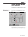
Creating Multistate
Indicators and Drawing Lines
Chapter 7
Creating Alarm Messages
Chapter 8
Creating and Configuring the Control List Selector without Enter Key
Editing the Control List Selector without Enter Key . . . . . . . . . . .
Configuring the Control List Selector without Enter Key . . . . . . . .
Creating the Selector Control . . . . . . . . . . . . . . . . . . . . . . . . . .
Validating the Screen . . . . . . . . . . . . . . . . . . . . . . . . . . . . . . . . . .
Viewing the Tag Usage for the Screen . . . . . . . . . . . . . . . . . . . .
Exiting the Screen . . . . . . . . . . . . . . . . . . . . . . . . . . . . . . . . . . . .
Creating and Configuring Multistate Indicators . . . . . . . . . . . . . . . .
Viewing the States of a Multistate Indicator . . . . . . . . . . . . . . . .
Adding the Stapler Multistate Indicator . . . . . . . . . . . . . . . . . . . .
Configuring the States . . . . . . . . . . . . . . . . . . . . . . . . . . . . .
Configuring the Multistate Indicator . . . . . . . . . . . . . . . . . . . .
Adding the Second Stapler Multistate Indicator . . . . . . . . . . . . . .
Drawing Lines and Arrows . . . . . . . . . . . . . . . . . . . . . . . . . . . .
Validating the Screen and Saving the Application . . . . . . . . . . . . . .
Adding Alarm Messages . . . . . . . . . . . . . . . . . . . . . . . . . . . . . . .
Downloading and Running
the Application
7–1
7–2
7–3
7–4
7–5
7–7
7–8
7–9
8–1
Chapter 9
Validating the Application . . . . . . . . . . . . . . . . . . . . . . . . . . . . . . .
Getting Ready to Download . . . . . . . . . . . . . . . . . . . . . . . . . . . . .
Downloading the Application . . . . . . . . . . . . . . . . . . . . . . . . . . .
Running the Application File . . . . . . . . . . . . . . . . . . . . . . . . . . . . .
Application Design Features . . . . . . . . . . . . . . . . . . . . . . . . . . .
Exiting the Tutorial . . . . . . . . . . . . . . . . . . . . . . . . . . . . . . . . . . . .
Index
Publication 2711E-818 – January 1998
6–1
6–3
6–5
6–6
6–8
6–9
6–10
9–1
9–1
9–2
9–2
9–3
9–3
Welcome to PanelBuilder
1400e Configuration
Software for Windows
Welcome to Allen-Bradley’s PanelBuilder 1400e Configuration
Software for Windows, Version 4. With this software you can create
applications in the Microsoft Windows 3.1 (or later) operating
system, Windows 95, and Windows NT 4.0. You run the
PanelBuilder applications on PanelView 1000e, 1200e, or 1400e
terminals, or PanelView 1200 Series F and later terminals that have
been enhanced to -MC catalog numbers.
PanelBuilder 1400e Configuration Software for Windows, Version 4,
provides the advantages that PanelBuilder 1400e, Version 3 offered,
as well as other enhancements. These include running on Windows
NT 4.0, increased ControlNet addressing, an Ethernet/RIO
Pass-Through File Transfer, RSLinx communication driver
compatibility, and a CD-ROM install.
For a more comprehensive description of each of these features, see
“What’s New in PanelBuilder 1400e, Version 4” in Chapter 1,
“Introducing PanelBuilder.”
Registering Your Copy of
PanelBuilder 1400e
To register your software, mail the registration card to this address:
Rockwell Software
Software Services
6680 Beta Drive
Mayfield Village, Ohio 44143
or fax the card to (440) 646-7701.
Available Documentation
Your PanelBuilder 1400e software comes with several types of
documentation to meet your different needs:
• Getting Started with PanelBuilder 1400e Configuration Software
for Windows (Publication Number 2711E-818) guides you
through setting up PanelBuilder 1400e and introduces you to
PanelBuilder 1400e basics. It includes a tutorial to give you
hands-on experience in creating and running a sample
application.
• The PanelBuilder 1400e Configuration Software for Windows
User Manual (Publication Number 2711E-819) explains
PanelBuilder 1400e in more detail, and provides step-by-step
instructions for planning, creating, and working with applications.
• The PanelBuilder 1400e Screen Objects Reference Manual
(Publication Number 2711E-820) provides detailed reference
information for application screen objects.
Publication 2711E-818 – January 1998
P–2
Preface
• The PanelBuilder 1200/1400e Transfer Utility User Manual
•
•
•
•
(Publication Number 2711E-6.8) provides detailed instructions
for transferring application files using the Transfer Utility that
comes with PanelBuilder 1400e, Version 4.
Context-sensitive Help provides a quick reference for any
procedures or commands you need explained, or problems you
may encounter. To get help, press F1 or choose the Help button if
you’re in a dialog box.
The PanelBuilder 1400e Readme file is a Microsoft Windows
Notepad file that is copied to your hard disk when you install
PanelBuilder 1400e. The Readme file informs you of any
software changes after the manuals were printed.
The PanelView 1000e, 1200e, and 1400e Operator Terminals
User Manual (Publication Number 2711E-821) describes how to
install, configure, maintain, and troubleshoot the PanelView
terminal.
The PanelBuilder 1400e Modbus User Manual (Publication
Number 2711E-6.12) describes how to create PanelBuilder
applications for the Modbus communications network. This
manual is supplied as part of the optional Modbus
Communications Kit, Catalog Number 2711E-UMOD.
A complete list of publications relating to PanelBuilder 1400e,
PanelView terminals, and programmable logic controllers (PLCs) is
available in the preface of the PanelBuilder 1400e User Manual.
What’s in Getting Started?
Getting Started introduces basic concepts for working with
PanelBuilder 1400e Configuration Software for Windows. This
manual is divided into two parts. The first part introduces you to
PanelBuilder 1400e and explains the basics for working with it. The
second part contains a tutorial that guides you through enhancing an
existing application, and running it on the PanelView terminal.
Preface
An overview of this manual, and lists of prerequisites, documentation
conventions, and related publications.
Chapter 1, Introducing PanelBuilder 1400e
An introduction to what PanelBuilder 1400e is, what it does, and
how it works with PanelView terminals and the PLC.
Publication 2711E-818 – January 1998
Preface
P–3
Chapter 2, Setting Up PanelBuilder 1400e
Step-by-step instructions for installing and starting
PanelBuilder 1400e.
Chapter 3, A Brief Tour of PanelBuilder 1400e
An overview of the PanelBuilder 1400e development environment,
components, and key concepts.
Chapters 4 to 9, The Tutorial
The tutorial is a task-oriented guide to enhancing and running a
sample application. Chapter 4 provides a tour of the sample
application: what it is, what it does, and how you’ll enhance the
application. Chapters 5 through 8 provide step-by-step instructions
for adding objects and messages. Chapter 9 tells you how to
download and run the application.
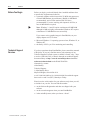
Who Should Read Getting Started?
Getting Started provides a comprehensive overview of PanelBuilder
1400e basics. Depending on your needs and previous knowledge,
certain sections may be more useful to you than others.
If this describes you
Read this
Unfamiliar with both PanelBuilder 1400e and Windows
Getting Started, Chapters 1
to 3
Windows user documentation
Familiar with PanelBuilder 1400e and want to know
new features of PanelBuilder 1400e, Version 4
Getting Started, Chapter 1
Want to know how to install PanelBuilder 1400e
Getting Started, Chapter 2
Want step-by-step guidelines to working in
PanelBuilder 1400e
Getting Started, Chapters 4
to 9
Want to know how a PanelBuilder 1400e application
runs in a PanelView terminal
Getting Started, Chapter 9*
*You can run the tutorial application without having to create it first.
Users who are not familiar with Microsoft Windows should read the
Microsoft Windows User’s Guide (for users of Windows 3.1),
Introducing Microsoft Windows 95 (for users of Windows 95), or
Introducing Microsoft Windows NT Workstation (for users of
Windows NT).
Publication 2711E-818 – January 1998
P–4
Preface
Terminology
The term PanelBuilder refers to PanelBuilder 1400e Configuration
Software for Windows. Where confusion may arise between the
current and previous versions of the software, the current release of
the software is “PanelBuilder 1400e, Version 4.”
Similarly, the terms terminal and PanelView terminal refer to a
PanelView 1000e, 1200e, or 1400e terminal, or enhanced PanelView
1200 Series F and G terminals. Where confusion may arise between
the 1200e and 1400e terminals and previous revisions, specific series
and revision names are used.
The terms programmable controller and PLC refer to the
Allen-Bradley line of Programmable Logic Controllers or any other
controlling device.
Conventions Used
Information is provided in a consistent way throughout the entire
PanelBuilder user documentation set. There are mouse selection,
shortcut key, and command conventions. Unless otherwise stated, all
dialog boxes and windows are captured in Windows NT.
Mouse Conventions
You can use a mouse with one or two buttons. This manual assumes
that if you have a multiple-button mouse, the left mouse button is
configured as the primary mouse button. Procedures that require you
to click a secondary button refer to it as the right mouse button.
Selection Conventions
Publication 2711E-818 – January 1998
This word or phrase
Means
Choose
Carry out a menu command or a command button in a dialog
box or Help window. Choose also means to double-click an
icon.
Choose OK
Either click the OK button with the mouse or press ENTER
on the keyboard to carry out the action.
Select
Either highlight the piece of text you want your next action to
affect, or select a specific dialog box option.
Click
Position the mouse pointer on the object, area, or field, and
click the left button once.
Double-click
Position the mouse pointer on the object, area, or field, and
click twice quickly.
Preface
P–5
Selection Conventions in Dialog Boxes
Dialog boxes contain standard Windows fields that require different
selection conventions. Refer to your Windows user documentation
for information on the selection conventions.
The following shortcut keys allow you to complete dialog boxes
faster:
This key or key
combination
Does this
TAB
Moves the cursor to the next field, option, or command
button.
SHIFT+TAB
Moves the cursor to the previous field, option, or command
button.
ALT+underlined letter
Selects an option, or displays a drop-down list.
ALT+
Displays a drop-down list.
SPACEBAR
Turns check boxes on or off.
Key Conventions
This key combination
Means
KEY1+KEY2
Press and hold the first key while you press the second
key. For example, press “CTRL+A” means to press the
CTRL key, and while pressing it, press the A key. Then
release both keys.
SHIFT-click
Press and hold the SHIFT key while you click an object
with the mouse pointer.
Command Conventions
Use any of the following three methods to carry out commands.
Instructions in this manual don’t always outline each method.
• choose a menu command
• choose an icon on the toolbar
• use a key combination
For example:
Use any of these commands to open an application
Choose Open Application from the File menu.
Click
from the toolbar.
Press CTRL+O.
Publication 2711E-818 – January 1998
P–6
Preface
Before You Begin
"
Before you begin, you should already have installed and know how
to operate this equipment and software:
• a personal computer with at least a 486, 25-MHz microprocessor;
at least 8 MB Random Access Memory (RAM) (16 MB RAM
recommended); and a SVGA monitor with 256 colors
(recommended). For users working with imported .dxf files, at
least 16 MB RAM is required.
Note: Windows 3.1 and 95 require a minimum of 8 MB RAM
although 16 MB are highly recommended. Windows NT requires
a minimum of 32 MB RAM to run successfully.
If you want to resize graphic images in PanelBuilder, set your
display adapter to 65,536 colors.
• Microsoft Windows 3.1 operating system or later, Windows 95, or
Windows NT
• the family of PLCs you’ll be monitoring and controlling
Technical Support
Services
If you have questions about PanelBuilder, please consult the manuals
or Help first. If you can’t find the answer, take advantage of our
Technical Support Fax Back system, available 24 hours a day, 7 days
a week at 1-440-646-5436, or browse through our technical support
document library at http://www.ab.com/mem/prodserv/services/
technotes/techmain.html on the World Wide Web.
Alternatively, contact:
Allen-Bradley
Technical Support
1 Allen Bradley Drive
Mayfield Heights, Ohio 44124-6118
or call 1-440-646-6800 or fax 1-440-646-6890 for technical support
between 8 AM and 5 PM (EST), Monday to Friday.
Please have the serial number for your software ready when you call,
or include it on your fax. You can find this number:
• on the Software Registration card that was shipped with your
software
• on the screen that appears when you start PanelBuilder
• in the main Help menu, when you choose “About”
Publication 2711E-818 – January 1998
Introducing PanelBuilder
1400e
This chapter provides an overview of PanelBuilder 1400e. It
describes these topics:
• what PanelBuilder is
• how PanelBuilder interacts with the PanelView terminal and the
PLC
• important new PanelBuilder features
About PanelBuilder 1400e
PanelBuilder 1400e is a software package that runs under Microsoft
Windows 3.1 or later, Windows 95, or Windows NT. With
PanelBuilder 1400e you create and design control panel applications
for PanelView operator terminals.
These control panel applications enable an operator to monitor and
control automated plant processes.
PanelBuilder, PanelView
Terminals, and the PLC
The relationship between PanelBuilder, the PanelView terminal, and
the PLC is as follows:
• PanelBuilder—The application is created in PanelBuilder on the
personal computer, and downloaded to the PanelView terminal
using the Transfer Utility.
• Programmable Logic Controller—When communicating over a
Remote I/O, Data Highway Plus, or ControlNet network, the PLC
can either respond to queries or solicit information from the
PanelView terminal and other input or output devices.
• PanelView terminal—The PanelView terminal displays the
process status information sent from the PLC. This information
enables the operator to make decisions about the process. The
operator provides input back to the PLC.
"
Note: The development computer doesn’t need to be connected to
the PLC or the PanelView terminal to create application files. It must
be connected only when you’re downloading or uploading the
application serially or over the PLC communications network. You
can also install the PanelView 1200/1400e Transfer Utility on a
portable computer, transfer the application to the portable computer,
and then upload or download the application from the portable
computer. See the PanelView 1200/1400e Transfer Utility User
Manual for details.
Publication 2711E-818 – January 1998
1–2
Introducing PanelBuilder 1400e
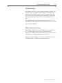
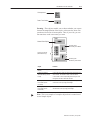
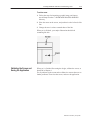
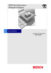
PanelBuilder 1400e
PanelBuilder is the development software package you use to create
and configure control panel application screens. Applications
developed with PanelBuilder software on a personal computer are
downloaded to PanelView terminals where they are run.
PanelBuilder
1400e Software
Development
Computer
PanelView Operator Terminals
The following terminals will run PanelBuilder 1400e applications:
• PanelView 1000e terminals, Series A and later, running Version 3
or later firmware
• PanelView 1200 Series F and later terminals that have been
enhanced with a PanelView 1200 Enhancement Kit (Catalog
Number 2711E-U1B12C), and are running Version 1 or later
firmware
• PanelView 1200e terminals, Series A and above, running Version 1
or later firmware
• PanelView 1400e terminals, Series A and above, running Version 1
or later firmware
Publication 2711E-818 – January 1998
"
Note: All other PanelView 1200 terminals will run only applications
created in PanelBuilder DOS (Catalog Number 2711-ND1) or
PanelBuilder 1200 (Catalog Number 2711-ND1W). They will not
run PanelBuilder 1400e applications.
"
Note: To communicate over a ControlNet network, you must use a
PanelView 1000e or 1400e terminal that has been upgraded to
include an ISA Card Adapter (Catalog Number 2711E-NA1 or
2711E-NA2) and a 1784-KTCX or 1784-KTCX15 card. Or you can
use the new PanelView 1400e terminals that support ControlNet
communications (Catalog Numbers 2711E-K14C7, 2711E-K14C15,
2711E-T14C7, 2711E-T14C15), or the new PanelView 1000e
terminals that support ControlNet communications (Catalog
Numbers 2711E-K10C7, 2711E-K10C15, 2711E-T10C7,
2711E-T10C15). These terminals are ready to use with your
ControlNet network.
Introducing PanelBuilder 1400e
1–3
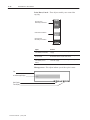
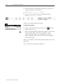
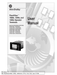
The application screens created in PanelBuilder appear on the
PanelView terminal, replacing traditional hard-wired control panels.
The screens provide the physical interface between the PLC and the
human operator.
Application screens contain objects that function like control panel
components. By using these objects to enter data or carry out
commands, the operator can monitor and control the process.
Touch Screen Terminals
Keypad Terminals
PanelView 1000e
Terminals
PanelView 1200e
Terminals
PanelView 1400e
Terminals
Publication 2711E-818 – January 1998
1–4
Introducing PanelBuilder 1400e
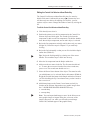
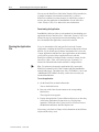
Programmable Logic Controller
When communicating over a Remote I/O, DH+, or ControlNet
network, the PLC can either respond to queries or solicit information
from the PanelView terminal and other input or output devices.
Programmable Logic
Controller
23737
The PanelView terminal is connected to a PLC in one of three ways:
• Remote I/O link—The PanelView terminal is connected to a
single controller. The controller sends process information to the
terminal, such as messages, numeric data, or alarms. It also
solicits the PanelView terminal for operator input.
• Data Highway Plus—The PanelView terminal is connected to a
peer-to-peer DH+ network that includes multiple controllers and
other devices. The terminal can control and monitor addresses in
these devices on the network.
• ControlNet—The PanelView terminal is connected to a
peer-to-peer ControlNet network. The terminal can control and
monitor addresses in these devices on the network.
The PanelView terminal can optionally be connected as a device to a
Modbus network. For more information about using PanelView
terminals with Modbus, see the PanelBuilder 1400e Modbus User
Manual, Publication Number 2711E-6.12.
Publication 2711E-818 – January 1998
Introducing PanelBuilder 1400e
1–5
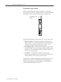
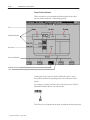
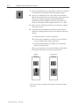
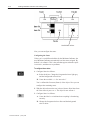
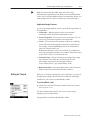
Understanding the Different Network Types
The relationship between the PanelView terminal and the PLC
depends on whether the terminal is part of a Remote I/O, Data
Highway Plus, or ControlNet network. The following illustration
shows the relationship between PanelBuilder, the PanelView
terminal, and the PLC.
In this example, the PanelView terminal is connected by
Remote I/O.
The application is created in PanelBuilder on the
personal computer, and downloaded to the
PanelView operator terminal.
The PLC receives information from the PanelView terminal (input), and uses this to
control the machine or process.
The PLC also sends process status information to the terminal (output).
Development Computer
Remote I/O
Serial Connection
Remote I/O
p
Programmable
Logic Controller
Machine or Process
Allen–Bradley
PanelView 1200e
PanelView 1000e/1200e/1400e Terminal (Touch Screen)
"
Tip: For connection diagrams, see Figures 2.1 through 2.7 in
Chapter 2, “Working with the PanelView 1200/1400e Transfer
Utility,” in the PanelView 1200/1400e Transfer Utility User Manual.
Publication 2711E-818 – January 1998
1–6
Introducing PanelBuilder 1400e
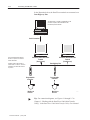
In the illustration below, the PanelView terminals are connected over
Data Highway Plus.
The application is created in PanelBuilder on the
personal computer, and downloaded to the
PanelView operator terminal.
Development Computer
Serial Connection
PanelView
Allen–Bradley
The PanelView terminal queries
the PLC for process or machine
status information.
PanelView 1000e/1200e/1400e
Terminal
(Touch Screen)
Operator input to the terminal is
sent to the PLC. The PLC uses this
information to control the machine
or process.
Programmable
Controller
Machine or
Process
"
Publication 2711E-818 – January 1998
PanelView
Allen–Bradley
PanelView 1200e
PanelView 1200e
PanelView 1000e/1200e/1400e
Terminal
(Touch Screen)
Data Highway Plus
Programmable
Controller
Machine or
Process
24717
Tip: For connection diagrams, see Figures 2.1 through 2.7 in
Chapter 2, “Working with the PanelView 1200/1400e Transfer
Utility,” in the PanelView 1200/1400e Transfer Utility User Manual.
Introducing PanelBuilder 1400e
1–7
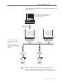
In the illustration below, the PanelView terminals are connected by a
ControlNet network.
The application is created in PanelBuilder on the
personal computer, and downloaded to the
PanelView operator terminal.
Development Computer
Serial Connection
PanelView
Allen–Bradley
PanelView
Allen–Bradley
PanelView 1000e
ControlNet PanelView
1000e/1400e Terminal
(Touch Screen)
The PanelView terminal queries
the PLC for process or machine
status information.
PanelView 1000e
ControlNet PanelView
1000e/1400e Terminal
(Touch Screen)
ControlNet
Operator input to the terminal is
sent to the PLC. The PLC uses this
information to control the machine
or process.
Programmable
Controller
Machine or
Process
"
Programmable
Controller
Machine or
Process
24717
Tip: For connection diagrams, see Figures 2.1 through 2.7 in
Chapter 2, “Working with the PanelView 1200/1400e Transfer
Utility,” in the PanelView 1200/1400e Transfer Utility User Manual.
Publication 2711E-818 – January 1998
1–8
Introducing PanelBuilder 1400e
What’s New in
PanelBuilder
1400e, Version 4
PanelBuilder 1400e, Version 4 provides expanded hardware support
to allow you to create applications for a wider variety of
environments, terminals, and networks.
Windows NT Compatibility
PanelBuilder 1400e Version 4 has been enhanced to run on a 32-bit
operating system, specifically Windows NT 4.0. However,
PanelBuilder 1400e, a 16-bit application, may still run on the 16-bit
platforms (Windows 3.1 or later, and Windows 95).
ControlNet Station Addressing
With PanelBuilder Version 4, you can now assign station addresses
from 1 to 99 on ControlNet. Previously, you could only assign
addresses above 63 using the terminal network setup screen at the
PanelView terminal.
Ethernet Pass-Through
Network users can now download or upload PanelBuilder 1400e
applications over an Ethernet network to a PanelView terminal on a
Remote I/O network. With the installation of an Ethernet network
card, you can now develop your PanelBuilder applications program
on a PC connected to an Ethernet network, and then download or
upload the applications to your PanelView terminals operating on a
Remote I/O network.
The Ethernet network card utilizes the PLC-5 (Enhanced) as a
pass-through device, enabling you to download your application to
the PanelView terminal.
Publication 2711E-818 – January 1998
Introducing PanelBuilder 1400e
1–9
CD-ROM Installation
PanelBuilder Version 4 can now be installed from a CD-ROM. This
not only reduces the number of disks required, but simplifies the
installation of PanelBuilder 1400e. However, for those who want
disk sets, you can create disks from the CD-ROM, or FAX or mail
the enclosed FAX Back Form to receive the requested package of
disks.
See the Readme file titled Floppies.txt in the root directory of the
PanelBuilder 1400e Installation CD for instructions on how to create
disks from the CD-ROM.
RSLinx Communication Drivers
PanelBuilder 1400e Version 4 will include RSLinx communication
drivers for application file transfers on Windows NT and
Windows 95. INTERCHANGE and WINLinx will still be available
for Windows 3.1 or later, and Windows 95, if desired.
Contact your local A-B Sales office or local distributor to purchase
INTERCHANGE or WINLinx communication drivers.
Publication 2711E-818 – January 1998
Setting Up PanelBuilder 1400e
This chapter covers these topics:
• hardware and software you need to run PanelBuilder
• installing PanelBuilder
• starting PanelBuilder for the first time
Requirements for Running
PanelBuilder
"
For installing and running PanelBuilder, the minimum system
requirements are:
• a personal computer (PC) with at least a 486, 25-MHz
microprocessor; at least 8 MB Random Access Memory (RAM)
for Windows 3.1; at least 16 MB RAM for Windows 95; at least
32 MB RAM for Windows NT 4.0; and a SVGA monitor with
256 colors (recommended). For users working with imported .dxf
files, at least 16 MB RAM is required.
• a permanent swap file.
Note: For Windows 3.1, the sum of RAM and swap space should
equal at least 16 MB. In the case of a PC with 8 MB RAM, for
example, you would need a swap file of at least 8 MB. For
Windows 95, a swap file of 32 MB is required. For Windows NT,
your swap file should equal the recommended amount in the Total
Paging File Size for all Drives dialog box under Virtual
Memory/System Properties. For details on configuring the swap
file, see your applicable Microsoft Windows User’s Guide.
• hard disk with 25 MB of free disk space (for installing)
• CD-ROM drive (or access to a CD-ROM drive for easy
installation)
• 3.5 inch high-density (1.44 MB) disk drive
• standard VGA (640 by 480) display adapter with at least 256
simultaneous colors (SVGA resolution of 800 by 600 or higher is
recommended)
If you want to resize graphic images in PanelBuilder, set your
display adapter to 65,536 colors.
• a mouse supported by Windows
• Microsoft Windows Version 3.1 or later, Windows 95, or
Windows NT 4.0
• Microsoft MS-DOS Version 3.3 or later (Version 5 or later
recommended)
Your system must be compatible with Windows. See your applicable
Microsoft Windows User’s Guide for specifications.
Publication 2711E-818 – January 1998
2–2
Setting Up PanelBuilder 1400e
Application File Transfer Equipment
One or more of the following equipment is needed for transferring
applications:
• an RS-232 serial port for uploading or downloading applications
with an Allen-Bradley upload/download cable
• a Data Highway Plus network card and connection (KT, KTX,
KF)
• a ControlNet network card and connection (1784-KTCX,
KTCX15)
For more information about the use of this optional equipment, see
the PanelView 1200/1400e Transfer Utility User Manual and the
PanelView 1000e, 1200e, and 1400e Operator Terminals User
Manual.
PanelView Terminal Requirements for Running PanelBuilder
1400e Applications
You can run applications created in PanelBuilder 1400e, Version 4,
on the following PanelView terminals:
• PanelView 1000e terminals, Series A and later, running Version 3
or later firmware
• PanelView 1200 Series F or later color terminals that have been
enhanced with PanelView 1200 Enhancement Kits (Catalog
Number 2711E-U1B12C), and are running Version 1 or later
firmware
• PanelView 1200e Series A or later terminals, running Version 1
or later firmware
• PanelView 1400e Series A or later terminals, running Version 1
or later firmware
"
Publication 2711E-818 – January 1998
Note: All other PanelView 1200 terminals will run only
applications created in PanelBuilder DOS (Catalog Number
2711-ND1) or PanelBuilder 1200 (Catalog Number
2711-ND1W). They will not run PanelBuilder 1400e
applications.
Setting Up PanelBuilder 1400e
"
CD-ROM Install
2–3
Note: To communicate over a ControlNet network, you must use
a PanelView 1000e, 1200e, or 1400e terminal that has been
upgraded to include an ISA Card Adapter (Catalog Number
2711E-NA1 or 2711E-NA2) and a 1784-KTCX or 1784-KTCX15
card. Or you can use the new PanelView 1400e terminals that
support ControlNet communications (Catalog Numbers
2711E-K14C7, 2711E-K14C15, 2711E-T14C7, 2711E-T14C15),
or the new PanelView 1000e terminals that support ControlNet
communications (Catalog Numbers 2711E-K10C7,
2711E-K10C15, 2711E-T10C7, and 2711E-T10C15). These
terminals are ready to use with your ControlNet network.
PanelBuilder 1400e is offered in the CD-ROM format. The
PanelBuilder 1400e CD contains these software applications:
PanelBuilder 1400e, PanelView 1200/1400e Transfer Utility, and the
Serial Firmware Upgrade Utility. RSLinx Lite software on 3.5-inch
floppy disks is also included in the PanelBuilder 1400e software kit;
when Version 4 is selected as the install version, RSLinx Lite
software provides communication drivers for network file transfers.
You can obtain 3.5-inch floppy disks of the software applications by
creating them from the PanelBuilder 1400e CD or by sending in the
FAX Back form provided with the PanelBuilder 1400e software kit
(A-B Catalog Number 2711E-ND1). For instructions on how to
create floppy disks of the software from the CD, refer to the file,
Floppies.txt, in the root directory of the PanelBuilder 1400e CD.
Note that the PanelBuilder 1400e application requires nine floppy
disks, the Transfer Utility application requires two floppy disks, and
the Serial Firmware Upgrade Utility application requires two floppy
disks.
The CD-ROM includes two install versions for the PanelBuilder
1400e software:
• Version 3—This version offers you PanelBuilder 1400e for use
with Windows 3.1 or later, or Windows 95. Version 3 supports
PanelView application file transfers over networks using
INTERCHANGE and WINtelligent LINX software drivers.
• Version 4—This version offers you PanelBuilder 1400e for use
with Windows 95 or Windows NT. Version 4 supports PanelView
application file transfers over networks using RSLinx software
drivers.
If your operating system is Windows 3.1 or later, the CD-ROM will
automatically install Version 3. If your operating system is Windows
95, you have the choice of installing Version 3 or Version 4, although
Version 4 is recommended. If your operating system is Windows NT,
the CD-ROM will automatically install Version 4.
Publication 2711E-818 – January 1998
2–4
Setting Up PanelBuilder 1400e
Installing PanelBuilder
1400e Version 4 from
CD-ROM on Windows NT
or Windows 95
To install PanelBuilder Version 4:
1. Start Windows NT or Windows 95. If you’re already in Windows,
close all open Windows applications.
2. Insert the CD-ROM in the drive.
The CD-ROM begins to run automatically.
3. If the install does not start automatically, choose Run from the
Start button and select setup.exe from the CD-ROM drive; or
select setup.exe from Windows Explorer.
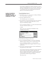
4. In the Welcome dialog box, choose Next.
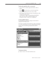
5. If you are installing on Windows 95, the Select Components
dialog box appears.
The CD-ROM includes two install versions for the PanelBuilder
1400e software:
• Version 3—This version offers you PanelBuilder 1400e for
use with Windows 3.1 or later, or Windows 95. Version 3
supports PanelView application file transfers over networks
using INTERCHANGE and WINtelligent LINX software
drivers.
• Version 4—This version offers you PanelBuilder 1400e for
use with Windows 95 or Windows NT. Version 4 supports
PanelView application file transfers over networks using
RSLinx software drivers.
Version 4, for use with Windows 95, is recommended. If you
choose Version 3, refer to “Installing PanelBuilder 1400e Version
3 from CD-ROM on Windows 95 or Windows 3.1 or later” in this
chapter for instructions. Otherwise, continue by selecting Version
4, and then choose Next.
Publication 2711E-818 – January 1998
Setting Up PanelBuilder 1400e
2–5
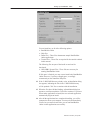
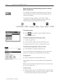
If you are installing on Windows NT, the Select Components
dialog box does not appear. Version 4 is automatically selected.
6. In the Choose Applications dialog box, choose PanelBuilder as
the application you want to install.
You can choose more than one application to install. Choose File
Transfer Utility for the ability to transfer application files
between a computer and the PanelView terminal. Choose Serial
Firmware Upgrade for the ability to upgrade the firmware on
your PanelView terminals using your computer.
Then choose Next.
7. In the registration window, enter your user name and company
name. After you enter the required information, choose Next.
8. In the confirmation window, verify the user information you have
entered. Select Yes to proceed, or No to edit the user information.
9. Close all open Windows applications. If you have done so,
choose Next.
10. In the registration window, enter registration information about
your copy of PanelBuilder 1400e.
The serial number for your software is on the Software
Registration card that was shipped with your software.
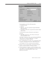
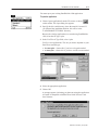
11. The Installation Options dialog box lists the program components
you are installing and the amount of hard disk space required for
each.
Choose the components you want to install and click Continue.
Publication 2711E-818 – January 1998
2–6
Setting Up PanelBuilder 1400e
You can install any or all of the following options:
• PanelBuilder 1400e
• Help files
• Demo files—These files demonstrate sample PanelBuilder
1400e applications.
• Tutorial files—These files are required for the tutorial outlined
in this manual.
The following files are part of the install set and cannot be
deselected:
• OLE/ODBC System Files—These files are necessary for
running PanelBuilder 1400e.
If disk space is limited, you may want to install only PanelBuilder
1400e. However, if you have enough space, we strongly
recommend you also install the Help files.
12. If the C:\RSI\CMN directory already exists, an Installation dialog
box appears, indicating the files in the C:\RSI\CMN directory
will be updated. Click Yes to continue with the installation.
13. When the files have finished loading, an Installation dialog box
appears to confirm completion. Click OK to continue. If you have
chosen other applications to install, the next selected application
automatically begins to install.
14. After all the applications have completed installing, you will be
prompted to reboot your computer. You may reboot immediately
or later, but you must reboot before you can run PanelBuilder
1400e or other applications successfully.
Publication 2711E-818 – January 1998
Setting Up PanelBuilder 1400e
2–7
If you choose to install the File Transfer Utility and you want to
upload or download PanelView files over the PLC networks, you
also need to install RSLinx Lite software, which is provided on
3.5-inch floppy disks. See the documentation provided with
RSLinx Lite for installation procedures.
Installing PanelBuilder
1400e Version 3 from
CD-ROM on Windows 95
or Windows 3.1 or later
To install PanelBuilder Version 3:
1. Start Windows 95, or 3.1 or later. If you’re already in Windows,
close all open Windows applications.
2. Insert the CD-ROM in the drive.
The CD-ROM begins to run automatically.
3. If the install does not start automatically and you are running on
Windows 95, choose Run from the Start button, or select
setup.exe from Windows Explorer.
If you are running on Windows 3.1 or later, choose Run from the
File menu. In the Run windows, type:
d:setup
where d is the drive containing the PanelBuilder 1400e
CD-ROM, and press Enter.
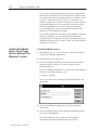
4. In the Welcome dialog box, choose Next.
5. If you are installing on Windows 95, the Select Components
dialog box appears. Choose Version 3, and then choose Next.
If you are installing on Windows 3.1 or later, the Select
Components dialog box does not appear. Version 3 is selected
automatically.
6. In the Choose Applications dialog box, choose PanelBuilder as
the application you want to install.
You can choose more than one application to install. Choose File
Transfer Utility for the ability to transfer application files
between a computer and the PanelView terminal. Choose Serial
Firmware Upgrade for the ability to upgrade the firmware on
your PanelView terminals using your computer.
Then choose Next.
Publication 2711E-818 – January 1998
2–8
Setting Up PanelBuilder 1400e
7. In the registration window, enter your user name and company
name. After you enter the required information, choose Next.
8. In the confirmation window, verify the user information you have
entered. Select Yes to proceed, or No to edit the user information.
9. Close all open Windows applications. If you have done so,
choose Next.
10. In the registration window, enter registration information about
your copy of PanelBuilder.
The serial number for your software is on the Software
Registration card that was shipped with your software.
11. The Installation Options dialog box lists the program components
you are installing and the amount of hard disk space required for
each.
Choose the components you want to install and click Continue.
Publication 2711E-818 – January 1998
Setting Up PanelBuilder 1400e
2–9
You can install any or all of the following options:
• PanelBuilder 1400e
• Help files
• Demo files—These files demonstrate sample PanelBuilder
1400e applications.
• Tutorial files—These files are required for the tutorial outlined
in this manual.
The following files are part of the install set and can’t be
deselected:
• OLE/ODBC System Files—These files are necessary for
running PanelBuilder 1400e.
If disk space is limited, you may want to install only PanelBuilder
1400e. However, if you have enough space, we strongly
recommend you also install the Help files.
12. If the C:\RSI\CMN directory already exists, an Installation dialog
box appears, indicating the files in the C:\RSI\CMN directory
will be updated. Click Yes to continue with the installation.
13. When the files have finished loading, an Installation dialog box
appears to confirm completion. Click OK to continue. If you have
chosen other applications to install, the next selected application
automatically begins to install.
14. After all the applications have completed installing, you will be
prompted to reboot your computer. You may reboot immediately
or later, but you must reboot before you can run PanelBuilder
1400e or other applications successfully.
Publication 2711E-818 – January 1998
2–10
Setting Up PanelBuilder 1400e
If you choose to install the File Transfer Utility and you want to
upload or download files over the PLC networks, you also need
to install INTERCHANGE or WINtelligent LINX software. If
you do not have this software, contact Allen-Bradley Technical
Support for assistance.
Installing PanelBuilder
1400e Version 4 from
Floppy Disks on Windows
NT or Windows 95
You can obtain 3.5-inch floppy disks of the software applications by
creating them from the PanelBuilder 1400e CD or by sending in the
FAX Back Form provided with the PanelBuilder 1400e software kit
(A-B Catalog Number 2711E-ND1). For instructions on how to
create floppy disks of the software from the CD, refer to the file,
Floppies.txt, in the root directory of the PanelBuilder 1400e CD.
Note that the PanelBuilder 1400e application requires nine floppy
disks, the Transfer Utility application requires two floppy disks, and
the Serial Firmware Upgrade Utility application requires two floppy
disks.
To install PanelBuilder Version 4:
1. Start Windows NT or Windows 95. If you’re already in Windows,
close all open Windows applications.
2. Insert the floppy disk in the drive.
3. Choose Run from the Start button and enter a:\setup.exe, or select
a:\setup.exe from Windows Explorer.
The installation begins.
4. Close all open Windows applications. If you have done so,
choose Next.
5. In the registration window, enter registration information about
your copy of PanelBuilder.
The serial number for your software is on the Software
Registration card that was shipped with your software.
6. The Installation Options dialog box lists the program components
you are installing and the amount of hard disk space required for
each.
Choose the components you want to install and click Continue.
Publication 2711E-818 – January 1998
Setting Up PanelBuilder 1400e
2–11
You can install any or all of the following options:
• PanelBuilder 1400e
• Help files
• Demo files—These files demonstrate sample PanelBuilder
1400e applications.
• Tutorial files—These files are required for the tutorial outlined
in this manual.
The following files are part of the install set and cannot be
deselected:
• OLE/ODBC System Files—These files are necessary for
running PanelBuilder 1400e.
If disk space is limited, you may want to install only PanelBuilder
1400e. However, if you have enough space, we strongly
recommend you also install the Help files.
7. If the C:\RSI\CMN directory already exists, an Installation dialog
box appears, indicating the files in the C:\RSI\CMN directory
will be updated. Click Yes to continue with the installation.
8. When the files have finished loading, an Installation dialog box
appears to confirm completion. Click OK to continue.
9. After the installation is complete, you will be prompted to reboot
your computer. You can reboot immediately or later, but you must
reboot before you can run PanelBuilder 1400e, or other
applications successfully.
Publication 2711E-818 – January 1998
2–12
Setting Up PanelBuilder 1400e
If you want to transfer application files between a computer and
the PanelView terminal, you must install the File Transfer Utility.
For instructions on how to install this utility, see Chapter 2 in the
PanelView 1200/1400e Transfer Utility User Manual. If you
choose to install the File Transfer Utility and you want to upload
or download PanelView files over the PLC networks, you also
need to install RSLinx Lite software, which is provided on
3.5-inch floppy disks. See the documentation provided with
RSLinx Lite for installation procedures.
If you want to upgrade the firmware on your PanelView terminal
using your computer, you must install the Serial Firmware
Upgrade Utility. For instructions on how to install this utility, see
Appendix D in the PanelView 1000e, 1200e, and 1400e Operator
Terminals User Manual.
Installing PanelBuilder
Version 3 from Floppy
Disks on Windows 95 or
Windows 3.1 or later
To install PanelBuilder Version 3:
1. Start Windows 95, or 3.1 or later. If you’re already in Windows,
close all open Windows applications.
2. Insert the floppy disk in the drive.
3. If you are running on Windows 95, choose Run from the Start
button and enter a:\setup.exe, or select a:\setup.exe from
Windows Explorer.
If you are running on Windows 3.1 or later, choose Run from the
File menu. In the Run windows, type:
a:setup
or b:setup
where a or b is the drive containing the PanelBuilder disk, and
press Enter.
4. Close all open Windows applications. If you have done so,
choose Next.
5. In the registration window, enter registration information about
your copy of PanelBuilder.
The serial number for your software is on the Software
Registration card that was shipped with your software.
Publication 2711E-818 – January 1998
Setting Up PanelBuilder 1400e
2–13
6. The Installation Options dialog box lists the program components
you are installing and the amount of hard disk space required for
each.
Choose the components you want to install and click Continue.
You can install any or all of the following options:
• PanelBuilder 1400e
• Help files
• Demo files—These files demonstrate sample PanelBuilder
1400e applications.
• Tutorial files—These files are required for the tutorial outlined
in this manual.
The following files are part of the install set and can’t be
deselected:
• OLE/ODBC System Files—These files are necessary for
running PanelBuilder 1400e.
If disk space is limited, you may want to install only PanelBuilder
1400e. However, if you have enough space, we strongly
recommend you also install the Help files.
7. Change the destination drive and directory, if desired. By default,
this is C:\AB\PB1400E. To change the destination drive or
directory, type the new drive and/or directory in the Directory
field.
If the Rockwell shared files have been installed previously, you
cannot change their location. If they haven’t yet been installed,
you can change the default directory.
Publication 2711E-818 – January 1998
2–14
Setting Up PanelBuilder 1400e
8. To proceed with installation, choose Continue. To cancel the
installation, choose Exit.
9. If the C:\RSI\CMN directory already exists, an Installation dialog
box appears, indicating the files in the C:\RSI\CMN directory
will be updated. Click Yes to begin the installation.
10. Follow the setup instructions as they appear on the screen.
To complete the setup, enter any required information and insert
disks when prompted. Continue this procedure until you have
installed all disks.
11. After the installation is complete, you will be prompted to reboot
your computer. You can reboot immediately or later, but you must
reboot before you can run PanelBuilder 1400e successfully.
If you want to transfer application files between a computer and
the PanelView terminal, you must install the File Transfer Utility.
For instructions on how to install this utility, see Chapter 2 in the
PanelView 1200/1400e Transfer Utility User Manual. If you
choose to install the File Transfer Utility and you want to upload
or download PanelView files over the PLC networks, you also
need to install INTERCHANGE or WINtelligent LINX software.
If you do not have this software, contact Allen-Bradley Technical
Support for assistance.
If you want to upgrade the firmware on your PanelView terminal
using your computer, you must install the Serial Firmware
Upgrade Utility. For instructions on how to install this utility, see
Appendix D in the PanelView 1000e, 1200e, and 1400e Operator
Terminals User Manual.
Accessing the
PanelBuilder 1400e
Readme File
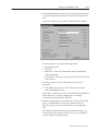
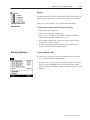
The PanelBuilder 1400e program group also contains a Readme file.
This file contains version-specific information, PanelView file
migration notes, and system installation and software registration
information. We recommend you read this file before proceeding.
You can also print the file.
To read the file:
"
Choose the Readme icon.
The README.TXT file appears on your screen.
To print the file:
1. Choose the Readme icon.
2. Choose Print from the File menu.
Publication 2711E-818 – January 1998
Setting Up PanelBuilder 1400e
Starting PanelBuilder
2–15
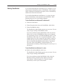
If you installed PanelBuilder with Windows NT or Windows 95, the
setup program automatically creates a PanelBuilder 1400e program
folder, containing the PanelBuilder program, which is automatically
added to the items on the Start menu.
If you installed PanelBuilder with Windows 3.1 or later, the setup
process automatically creates and places the PanelBuilder 1400e
program group and icon in the Program Manager.
To start PanelBuilder from Windows NT or Windows 95:
1. Choose the Start button.
2. Choose Programs, then choose the PanelBuilder 1400e folder.
3. Choose PanelBuilder 1400e.
The PanelBuilder 1400e Window appears on your screen. You are
ready to begin working in PanelBuilder 1400e.
If you have problems running PanelBuilder 1400e and you have
had previous versions of PanelBuilder 1400e on your computer,
we recommend you select “Uninstall PanelBuilder 1400e” in the
PanelBuilder 1400e folder. The “Uninstall PanelBuilder 1400e”
program deletes any of the shared files and windows system file
conflicts that may exist from earlier installations. You will then
have to reinstall the PanelBuilder 1400e software. If problems
still exist, contact Allen-Bradley Technical Support. For
information about obtaining Technical Support, see the Preface in
this manual.
To start PanelBuilder from Windows 3.1 or later:
"
Double-click the PanelBuilder 1400e icon.
The PanelBuilder 1400e Window appears on your screen. You are
ready to begin working in PanelBuilder.
If you have problems running PanelBuilder 1400e, check the
Readme.txt file for potential system conflicts, and contact
Allen-Bradley Technical Support. For Technical Support
information, see the Preface in this manual.
Publication 2711E-818 – January 1998
A Brief Tour of PanelBuilder
1400e
This chapter introduces you to the basics of PanelBuilder 1400e. It
informs you about these topics:
• creating and opening PanelBuilder 1400e applications
• key concepts to help you understand how PanelBuilder 1400e
works
• PanelBuilder 1400e components and how to use them
This chapter does not provide a detailed discussion of how the
Windows operating system works. If you are unfamiliar with
Windows, refer to your Windows documentation first.
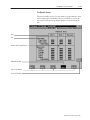
"
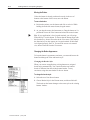
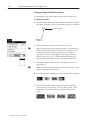
Creating a New
Application
Tip: Create a new application, or open a demo or tutorial
application, as described in the next two sections. Follow along and
learn about the program as you read the rest of this chapter.
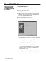
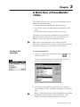
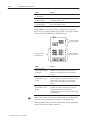
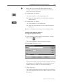
To create a new application:
1. Choose New Application from the File menu or
toolbar. Or, press CTRL+N.
from the
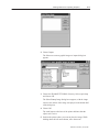
The New Application dialog box appears, where you must
specify the type of application you are creating.
2. Select the type of terminal the application will be running on.
Select Remote I/O, DH+, ControlNet, or Modbus as the network
type.
"
Note: For information about creating a PanelBuilder application
for Modbus communications, see the PanelBuilder 1400e
Modbus User Manual, Publication Number 2711E-6.12.
Publication 2711E-818 – January 1998
3–2
A Brief Tour of PanelBuilder 1400e
Important:
"
You cannot convert a keypad application to a
touch screen application, or vice-versa.
However, you can switch between 1000e, 1200e,
and 1400e application types, and you can change
the application’s network type.
Tip: You can copy display objects between applications for
different terminal types to reduce the amount of time required to
create a keypad application from an existing touch screen
application, or vice-versa. See the PanelBuilder 1400e
Configuration Software for Windows User Manual for details.
3. Choose OK.
The Application Window opens inside the PanelBuilder 1400e
Window.
Opening Applications
If you have existing PanelBuilder 1400e, PanelBuilder for DOS, or
PanelBuilder 1200 applications, you can open them. For information
about opening applications created in other versions of PanelBuilder,
see PanelBuilder 1400e Configuration Software for Windows User
Manual.
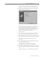
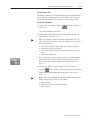
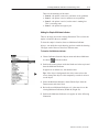
To open an existing application:
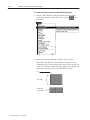
1. Choose Open Application from the File menu or
toolbar. Or, press CTRL+O.
from the
The Open dialog box appears. It lists the available applications in
the specified drive and directory. If no applications are listed, you
may need to change the drive or directory, or list another type of
application, for example, a PanelBuilder for DOS .cfg
application.
Publication 2711E-818 – January 1998
A Brief Tour of PanelBuilder 1400e
3–3
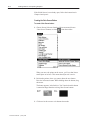
"
Tip: To open an existing application so you can follow along as
you read this chapter, double-click the PB1400e folder to display
the DEMO and TUTORIAL folders, then double-click DEMO or
TUTORIAL and select an application.
"
Note: The TUTORIAL folder contains two Remote I/O
applications—one for keypad terminals and one for touch screen
terminals as well as four Modbus applications—two for keypad
terminals and two for touch screen terminals. The DEMO folder
contains two Data Highway Plus applications—one for keypad
and one for touch screen terminals.
2. Select the application you want to open.
3. Choose OK.
If your system doesn’t have enough memory to run the
application, the following message appears:
“PanelBuilder 1400e has detected low memory resources”
You must quit one or more currently open software applications,
or currently open applications in PanelBuilder 1400e, before you
can open another PanelBuilder 1400e application.
Publication 2711E-818 – January 1998
3–4
A Brief Tour of PanelBuilder 1400e
Key Concepts
To understand how PanelBuilder 1400e works, you need to know the
following concepts.
PanelBuilder 1400e Window
The PanelBuilder 1400e Window is the first window that appears
when you start PanelBuilder 1400e. In it you create and configure
applications.
Application
An application is a file that you create and configure in PanelBuilder
1400e. You download the completed application to a PanelView
terminal, where it appears as a set of screens and screen components.
The operator uses these components to monitor and control the
operations of an automated process or machine.
For a detailed example of a photocopying application, see the tutorial
beginning in Chapter 4 of this manual.
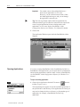
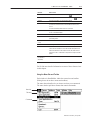
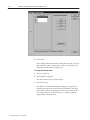
Application Window
Each application has its own window that appears within the
PanelBuilder 1400e Window. This window is called the Application
Window. Through it you can access all the components that make up
a single application.
Publication 2711E-818 – January 1998
A Brief Tour of PanelBuilder 1400e
3–5
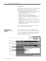
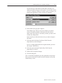
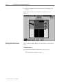
Application
Window
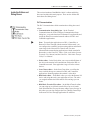
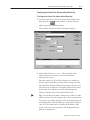
The Application Window contains all the dialog boxes and editors
you will use to build and configure the application. These are
contained in folders. The application’s name is listed in the
Application Window title bar, as well as the type of tag database
used. In this example, the database is private.
Application
Window
Folder
Dialog Box
Editor
Publication 2711E-818 – January 1998
3–6
A Brief Tour of PanelBuilder 1400e
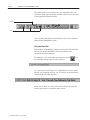
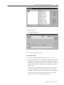
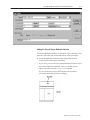
Folders
The Application Window contains four folders, which contain
groupings of editors or dialog boxes.
This folder
Contains
PLC Communications
Dialog boxes and editors for configuring communications with
the PLC. This includes setting up nodes and scan classes for
Data Highway Plus, ControlNet, and Modbus applications, and
configuring racks and block transfer files for Remote I/O
applications.
System
Dialog boxes and editors for configuring the terminal, tag
database, alarms, PLC I/O Control options, and the Information
Message Window.
Messages
Editors for creating information, local, and alarm messages.
Screens
Application screens developed with PanelBuilder 1400e
software. There are no screens in a new application.
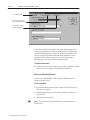
Dialog Boxes
Dialog boxes are used to configure specific properties of the
application. For example, in the Configure Terminal Setup dialog
box, you assign the Application Startup screen and target firmware
version for the application and specify timing parameters such as
hold times for push buttons. Frequently, dialog boxes are arranged
into tabs, according to the type of information. For example, the
Configure Terminal Setup dialog box has a General tab, a Timing
Parameters tab and, for function-key applications, an Object Setup
tab.
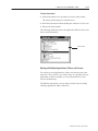
Editors
Editors are the tools for creating and configuring the more complex
components of an application in PanelBuilder 1400e. For example,
in the Tag Database editor you create and edit tags. In the Messages
editors you create messages that appear when the application is
running. With the Expressions Editor you create expressions to
manipulate the display of tag values at the PanelView terminal and
reduce the complexity of PLC ladder logic.
Publication 2711E-818 – January 1998
A Brief Tour of PanelBuilder 1400e
3–7
Tag Database
Each application must have a tag database. This database can be
specific to that application (private), or common to several
applications (shared). The tag database contains tags. Tags are
mnemonic representations of numeric addresses on the PLC.
Each tag is assigned an appropriate address location in the
programmable controller. In turn, the tags are assigned to objects,
I/O control options, and terminal windows. The same tag can be
assigned to several objects.
Application Screens
Application screens contain objects the operator uses to monitor and
control the process. The application screens you create in
PanelBuilder 1400e appear on the PanelView terminal when the
application is running.
Alarm Screens
The Alarm History and Alarm Status screens provide information on
alarms that occur while the application is running.
Windows
System windows pop up on screens when the application is running,
providing information to the operator.
Although there are a number of pre-defined system windows that can
appear, the only ones you can configure in PanelBuilder 1400e are
the Information Message Window and the Alarm Message Window.
Publication 2711E-818 – January 1998
3–8
A Brief Tour of PanelBuilder 1400e
Screen Objects
Application screens contain objects such as push buttons, bar graphs,
or screen selectors. These objects replace the components of
traditional control panels. There are several types of objects:
• Input to programmable logic controller—Objects such as push
buttons allow the operator to send information to the
programmable logic controller.
• Display information from programmable logic
controller—Objects such as bar graphs and multistate indicator
objects display information from the programmable logic
controller.
• Screen change objects—Static objects such as Goto Screen
buttons allow the operator to control screen changes at runtime.
• Drawing objects—Static objects such as lines, text, and graphic
images enhance the appearance of the screen and provide
information to the operator.
Objects are created in the application screen editor. You can also
import graphic images into the screen editor.
Working in the
PanelBuilder 1400e
Window
This section explains the features of the PanelBuilder 1400e
Window, and shows you how to use basic PanelBuilder 1400e tools.
The following illustration shows the PanelBuilder 1400e Window
with an Application Window. All the elements contained in the
window are explained in the next table.
Close Button
Title Bar
Maximize Button
Minimize Button
Control Menu
Menu Bar
Toolbar
Mouse
pointer
Application
Window
Window
Border
Status Bar
Publication 2711E-818 – January 1998
A Brief Tour of PanelBuilder 1400e
3–9
Element
How to use it
Minimize button
To reduce the window to an icon, choose
Maximize button
To enlarge the window to its maximum size, choose
Title bar
To move the window, click and drag the title bar.
Control box
To open the control box menu, click the box or use ALT+SPACEBAR.
To close the control box menu, click outside the menu or press
ESCAPE.
To close the window, double-click the Control box.
Menu bar
To open the menu and see the commands, choose a menu name
or use ALT+underlined letter.
Toolbar
To carry out a command, choose an icon.
Application Window
To open folders, double-click them. Then you can launch editors or
open dialog boxes.
Mouse pointer or
cursor
To select or choose items, use the mouse pointer.
Window Border
To change the window size, click the border and drag it.
Status bar
To see what a menu command or toolbar icon will do, move the
cursor over the command or icon and read the description in the
status bar. When the Screen editor is active, the status bar also
shows the X and Y coordinates for the position of objects and the
pointer.
Restore button
(not shown in
illustration)
Click either arrow to restore the window to mid-size.
You’ll find more detailed information on most of these features later
in this chapter.
Using the Menu Bar and Toolbar
Each window in PanelBuilder 1400e has a menu bar and toolbar.
(Dialog boxes do not have menus and toolbars.)
The menu bar and toolbar let you choose and carry out commands.
The menu bar has pull-down menus that contain commands.
Menu bar
File menu
Commands
Publication 2711E-818 – January 1998
3–10
A Brief Tour of PanelBuilder 1400e
The toolbar consists of icons that carry out commands when you
click them. Each icon corresponds to either a menu item or an editor
in the Application Window folders.
Toolbar
Icons
You will notice that the menu bar changes as you work in different
editors within PanelBuilder 1400e.
Using the Status Bar
Each window in PanelBuilder 1400e has a status bar. The status bar
informs you about PanelBuilder 1400e components, tools,
commands, and error messages.
For example, if you position the mouse pointer over the
the following message appears in the status bar.
icon,
Or, if you select a screen object in an application screen, the status
bar tells you what kind of object you’ve selected, its position on the
screen, height and width, and state.
In the Screen editor, as you move the mouse pointer, the status bar
displays the pointer’s coordinates on the screen.
Publication 2711E-818 – January 1998
A Brief Tour of PanelBuilder 1400e
Working in the Application
Window
3–11
To access the editors in the Application Window, you must open the
folders.
Folders that look like this contain components.
Folders that look like this are open.
Folders that look like this are empty.
To open or close a folder, use the following methods:
• double-click the folder
• to open a closed folder, select the folder, then press the + key on
the keypad
• to close an open folder, select the folder, then press the – key on
the keypad
Starting Editors
You can use two different methods to start an editor.
To start an editor:
• Click the icon of the editor in the toolbar.
• Double-click the editor in the Application Window.
Using Tabs in Dialog Boxes
Some dialog boxes have different categories of options or application
properties you can configure. These are organized into tabs. You can
select the tab you want to work in, and configure the desired options.
Then, if you wish, you can select another tab.
When you choose OK, all the changes to all the tabs in the dialog
box are accepted. When you choose Cancel, the dialog box closes.
All changes to all tabs are lost.
For example, for a keypad application the Configure Terminal Setup
dialog box consists of the General tab, the Timing Parameters tab,
and the Object Setup tab.
Publication 2711E-818 – January 1998
3–12
A Brief Tour of PanelBuilder 1400e
This is the active tab
Click on this to switch to
the Timing Parameters tab
Click on this to switch to
the Object Setup tab
In the General tab you can specify the Application Startup screen,
select the application type, enter an application file comment, and
specify the target firmware version. In the Timing Parameters tab
you can specify times for the different timing parameters in the
application. In the Object Setup tab, you can set options that
determine how some objects behave at the terminal.
To switch between tabs:
"
Click on the tab for the parameters you want to configure, or hold
down the ALT key, and press the underlined character.
Moving and Resizing Windows
You can move PanelBuilder 1400e windows and dialog boxes
anywhere on the screen.
To move a window:
1. Position the mouse pointer on the window’s title bar, and press
the left mouse button.
2. While holding down the mouse button, drag the window to its
new position.
3. Release the mouse button.
"
Publication 2711E-818 – January 1998
Note: You can resize all editor windows, but you cannot resize
dialog boxes.
A Brief Tour of PanelBuilder 1400e
3–13
To resize the window:
1. Position the pointer over any border or corner of the window.
The mouse pointer changes to a double arrow.
2. Hold down the mouse button and drag the window to its new size.
3. Release the mouse button.
The following illustration shows the Application Window after it has
been resized horizontally.
Resize Arrow
Working with Multiple Applications, Editors, and Screens
You can have several applications, editors, and screens open at the
same time. This is useful if you want to move or copy data from one
application or editor to another, or access information in several
screens simultaneously.
The Window menu helps you keep track of what is open by listing
each open application, editor, and screen.
Publication 2711E-818 – January 1998
3–14
A Brief Tour of PanelBuilder 1400e
Which Window is Active?
Although you can have multiple windows open, only one window is
active at a time. To enable you to identify the active window, the title
bar of the active window is highlighted, as the following illustration
shows.
Active window
To see which window is currently active:
"
Choose Window in the menu bar.
The Window menu lists all open applications, editors and screens.
The active window has a check mark (n). For example, the
following illustration shows that the Application Window for
Application – BOTTLING is active. The other windows are also
open, but are not active.
This window is active
These windows are open
Publication 2711E-818 – January 1998
A Brief Tour of PanelBuilder 1400e
3–15
To make another application, editor, or screen active:
• Click anywhere on another Application Window, editor, or
screen.
• Choose
from the toolbar to activate the Application
Window corresponding to the active screen or editor.
• In the Window menu, choose the name of the application, editor,
or screen you want to activate.
A check mark (n) appears next to the name in the Window
menu. The screen, editor, or application appears in the
PanelBuilder window, with the title bar highlighted.
Arranging Multiple Windows
You can organize your desktop by using the Cascade and Tile
commands in the Window menu.
The Cascade command stacks and offsets the windows horizontally,
so you can see their title bars. The Tile command arranges all open
windows as tiles. The following illustration shows the Tile
command.
To arrange open windows:
"
Choose Cascade or Tile from the Window menu.
Publication 2711E-818 – January 1998
3–16
A Brief Tour of PanelBuilder 1400e
Reducing, Restoring, and Maximizing Applications, Message
Editors, and Screens
An advantage of the Windows environment is that you can have
several windows open at the same time. But sometimes this can
clutter your workspace.
To avoid clutter, reduce windows to icons. This is called
“minimizing.” The following illustration shows the icons of a
minimized message editor, application, and screen.
To minimize a window:
"
Choose
in the window or choose Minimize from the
window’s Control menu.
To minimize an application and all its open screens:
1. Click on the application.
2. Choose Minimize Application from the Window menu.
The application and all its screens are minimized into icons.
To minimize all open applications, editors or screens:
"
Choose Minimize All from the Window menu.
The icons are displayed in the PanelBuilder window. If you have
many icons, you may want to arrange them to avoid clutter.
To arrange icons:
"
Choose Arrange Icons from the Window menu.
This arranges all icons in a row at the bottom of the PanelBuilder
window.
When you need to work in the application, editor, or screen, restore
the icon to its original size.
To restore an icon:
"
Publication 2711E-818 – January 1998
Double-click the icon. Or, in the Window menu, select the name
of the application, editor, or screen you want to restore. Or, click
the icon and choose Restore from its Control menu.
A Brief Tour of PanelBuilder 1400e
3–17
To maximize a window or application:
"
Choose
in the window or choose Maximize from the
window’s Control menu.
Using Menus, Keys, and Icons
Menus contain all the actions or commands you can carry out in
PanelBuilder 1400e. Icons on the toolbar also perform certain menu
commands. You can also carry out some commands using the key
combinations shown in the menus.
To create a new application, use any of these methods:
• Choose
on the toolbar.
• Choose New Application from the File menu.
• Press the CTRL and N keys simultaneously.
Using the Control Menus
All windows and dialog boxes in PanelBuilder 1400e contain a
Control menu. The Control menu changes depending on the window
you’re in. Dialog boxes contain only the Move and Close commands.
Publication 2711E-818 – January 1998
3–18
A Brief Tour of PanelBuilder 1400e
This command
Does this
Restore
Restores the window to its previous size after you’ve
maximized or minimized it.
Move
Allows you to use the keyboard to move the window or
dialog box.
Size
Allows you to use the keyboard to resize the window.
Minimize
Reduces the window to an icon.
Maximize
Enlarges the size of the window to fill a larger portion of
the desktop or the entire desktop.
Close
Closes the window or dialog box. In a dialog box, choosing
Close is the same as choosing Cancel. You lose any
changes made to dialog controls.
If you choose Close from PanelBuilder 1400e Window’s
control menu, PanelBuilder 1400e closes.
Switch to . . .
Opens a Task List dialog box that lets you switch between
running Windows applications. You can also use this
command to move between Windows and DOS.
Next
Switches between an open editor and the Application
Window.
Using Help
You can use Help whenever you see Help on the menu bar, or see a
Help button.
To access Help, do any of the following:
• Choose Help from the menu bar. This displays the Help menu.
Choose Help Index to go to the Contents window. Then select the
topic you want.
• Press F1 to display Help about the currently active window.
• Choose the Help command button in text or dialog boxes to
display specific information about the dialog box.
"
Publication 2711E-818 – January 1998
Tip: Keep Help handy by resizing the Help window and moving
it next to the PanelBuilder 1400e Window.
A Brief Tour of PanelBuilder 1400e
Inside the Editors and
Dialog Boxes
3–19
This section introduces PanelBuilder 1400e’s editors and dialog
boxes and explains their main purpose. These are the folders and
their editors and dialog boxes:
PLC Communications
The PLC Communications folder contains these dialog boxes and
editors:
• Communication Setup dialog box—In the Terminal
Communications tab of the Configure Communication Setup
dialog box, you set the baud rate for Remote I/O applications and
assign the PanelView terminal network address for DH+ and
ControlNet applications.
"
Note: To transfer the application over DH+, ControlNet, or
Remote I/O Pass-Through with the terminal in Run mode, you
can configure the terminal’s location routing address and transfer
control tags in the Network File Transfer tab. For more
information about transferring applications with the terminal in
Run mode, see the PanelView 1000e, 1200e, and 1400e Operator
Terminals User Manual, and the PanelView 1200/1400e Transfer
Utility User Manual.
• Nodes editor—In the Node editor you set up node definitions of
the devices the terminal will communicate with on the DH+ or
ControlNet network. Your application’s tags will refer to these
devices.
• Scan Classes editor—In the Scan Class editor you define the
rates at which the tags are scanned for DH+ and ControlNet
applications. Scanning updates the terminal’s value table.
• RIO Racks editor—In the Rack editor you select the Remote I/O
device and assign the racks your application will use. The racks
you assign determine the block transfer files and tags you can
create.
• RIO Block Transfer Files editor—In the Block Transfer editor
you can assign up to 64 block transfer files of up to 64 words
each. Block transfer files provide more address space for tags. In
this editor you can also configure the Pass-Through Control byte
for Remote I/O Pass-Through application file transfers.
Publication 2711E-818 – January 1998
3–20
A Brief Tour of PanelBuilder 1400e
System
• Configure Terminal Setup dialog box—In the Configure
•
•
•
•
Terminal Setup dialog box you can describe the application, set
timing parameters such as push button hold times or auto-repeat
rates, assign the Application Startup screen, select a different
application type, and specify the target firmware version. For
keypad applications, you can also specify default settings for
object behavior.
Tag Database editor—In the Tag Database editor you can create
and edit tags and tag folders.
Alarms dialog box—In the Configure Alarms dialog box you
can assign alarm tags, and configure the Alarm History and
Alarm Status screens and the Alarm Message Window.
PLC I/O Control dialog box—In the PLC I/O Control dialog
box you specify whether the PLC monitors and/or controls certain
terminal functions. For example, the PLC-Controlled Screen
Number option allows the PLC to control which screen appears
on the terminal.
Information Message Window dialog box—In this dialog box
you can enable the Information Message Window, specify how
the window is removed, configure its appearance, and assign tags.
Messages
Messages inform the operator about what is happening when the
application is running. For example, if a pump fails or a tank is
almost full, the operator should be informed.
• Alarm Messages alert the operator to problems in the process.
Alarm messages can appear in the Alarm Message Window that
pops up over the application screen. Alarm messages have special
options to alert the operator. They can trigger audio alarms,
energize relays, activate the printer, send a message to the PLC,
or be displayed in the Alarm Message Window.
• Information Messages inform the operator about the status of
the operation and provide prompts, instructions, or warnings.
These messages appear in the Information Message Window that
pops up over the application screen.
• Local Messages inform the operator about the status of screen
operations or provide prompts and instructions. Unlike alarm and
information messages, local messages are not displayed in pop-up
windows. Instead, they appear in Local Message Display objects
in screens.
Publication 2711E-818 – January 1998
A Brief Tour of PanelBuilder 1400e
3–21
Screens
Use the Screen editor tools to create the application screens that will
appear when the application is running on the PanelView terminal.
Closing Editors and
Applications
There are several methods to close editors and applications.
To close editors and applications do any of the following:
• Double-click the Control box.
• Choose Close from the Control menu.
• Press CTRL+F4. To close the Tag Database, RIO Racks, Block
Transfer Files, and Node editors, press ALT+F4.
• If the editor or application is the active window, choose Close
from the File or Screen menu.
• To close all open applications, message editors, and screens,
choose Close All from the Window menu.
Exiting PanelBuilder
To exit PanelBuilder 1400e:
"
Choose Exit from the File menu, or double-click in the Control
box of the PanelBuilder 1400e Window.
If applications are open when you choose Exit, they will all close
when you exit PanelBuilder 1400e. If the applications contain
unsaved changes, PanelBuilder 1400e will prompt you to save the
changes.
Publication 2711E-818 – January 1998
Introduction to the Tutorial
This chapter introduces you to the application you’ll be working with
in this tutorial. It tells you about these topics:
• what the existing application does, and how you will enhance it
• the functions of each application screen and the uses of each
object
This tutorial is also available in Modbus Programmable Controller
format. For information about running this tutorial with Modbus, see
the PanelBuilder 1400e Modbus User Manual, Publication Number
2711E-6.12, supplied as part of the optional Modbus
Communications Kit, Catalog Number 2711E-UMOD.
Purpose of the Tutorial
This tutorial is designed to get you started with PanelBuilder 1400e
quickly and easily. This chapter provides an overview of the tutorial.
Chapters 5, 6, and 7 provide instructions for adding objects to the
existing screens. Chapter 8 shows you how to add messages.
Chapter 9 shows you how to download the file to the PanelView
terminal, so you can run it.
A second purpose of this tutorial is to show good application design
principles in action.
"
Before You Start
Note: If you want to run the completed application without creating
any of it yourself, you can do so. Simply go to Chapter 9 and follow
the instructions for downloading the file. Then run it on the terminal.
You can do this at any point in the tutorial.
Before you start the tutorial, ensure you’ve done the following:
• installed the Tutorial files. These contain the application files that
you’ll need for the tutorial. For more information, see Chapter 2.
• familiarized yourself with PanelBuilder 1400e basics. To do this,
read the first part of this manual.
Also, ensure that you have the required equipment. You’ll need:
• PanelBuilder 1400e installed
• a PanelView 1000e terminal, or an enhanced PanelView 1200
Series F or later terminal, or a PanelView 1200e terminal, or a
PanelView 1400e terminal
• PLC controller
Publication 2711E-818 – January 1998
4–2
Introduction to the Tutorial
"
Understanding the
Scenario
Note: The ladder logic for this application was developed on a
PLC 5/15. You can use the ladder logic on any PLC controller that is
compatible with the PLC 5/15.
This tutorial is based on the following scenario.
You have an existing application, created with PanelBuilder 1200,
that runs a paper copying process. The machine controlled by this
application is a lower-end model and doesn’t have a stapling feature.
Now you’ve decided to purchase a new machine that supports
stapling. To use this feature, you must add the required controls to
your existing PanelBuilder 1200 application. As well, you realize
that your existing application is not as well-designed as it could be.
You want to fine-tune it to make it easier to use, and to improve the
appearance of the application with more colors and better graphics.
To do these tasks quickly and efficiently, you’ve purchased
PanelBuilder 1400e Configuration Software for Windows.
This chapter of the tutorial guides you through the existing
application, the application screens, and the objects each screen
contains. It explains how the objects enable you to control and
monitor the copying process.
It also outlines the objects you will add.
Starting
PanelBuilder 1400e
To do this tutorial, you must have PanelBuilder 1400e and the
tutorial files installed.
To start PanelBuilder from Windows NT or Windows 95:
1. Choose the Start button.
2. Choose Programs, then choose the PanelBuilder 1400e folder.
3. Choose PanelBuilder 1400e.
The PanelBuilder 1400e Window appears on your screen. You are
ready to begin working in PanelBuilder.
To start PanelBuilder from Windows 3.1 or later:
"
Double-click the PanelBuilder 1400e icon.
The PanelBuilder 1400e Window appears on your screen. You are
ready to begin working in PanelBuilder.
Publication 2711E-818 – January 1998
Introduction to the Tutorial
4–3
You must open your existing PanelBuilder 1200 application.
To open the application:
1. Choose Open Application from the File menu, or choose
on the toolbar. The Open dialog box appears.
2. Specify the drive and directory where the tutorial is located. If
you followed the installation defaults, this will be in the
C:\AB\PB1400E\TUTORIAL directory.
Because the existing application was created using PanelBuilder
1200, it has the file type *.pbw
3. In the List Files of Type field, select *.pbw.
You’ll see two applications. The one you choose depends on your
PanelView terminal type:
• kc-tutor.pbw—choose this if you have a keypad terminal
• tc-tutor.pbw—choose this if you have a touch screen terminal
4. Select the appropriate application.
5. Choose OK.
A message appears, informing you that converting the application
will make it compatible with PanelView 1400e Version 1 and
later firmware.
Publication 2711E-818 – January 1998
4–4
Introduction to the Tutorial
6. Choose OK.
A dialog box appears, informing you of the conversion status.
When the conversion is finished the Application Window appears.
The application’s name is displayed in the title bar.
"
Note: This application is configured for Remote I/O. While you
could switch network types to Data Highway Plus, ControlNet, or
Modbus for the purpose of this tutorial the application will remain
configured for Remote I/O.
Before you start editing it, save the application.
To save the application:
1. Choose Save Application As... from the File menu.
2. Specify the drive and directory where you want to save the file, or
accept the default directory.
3. If you want to rename the file, type a new name for your file in
the File Name field. Or, you can save the application under the
existing name. Because it will be saved under a different file
extension, it won’t overwrite the existing file.
4. Choose OK.
Note that PanelBuilder 1400e automatically adds .pvc as the file
extension.
Once you’ve saved your file, you can start editing it. You can go
directly to Chapter 5 and continue the tutorial. But we recommend
that you complete this chapter first because it guides you through the
existing screens and explains how the objects work. In addition, it
explains the features you’ll be adding to enhance the application.
Viewing the Application
Screens
Publication 2711E-818 – January 1998
The copier application contains four application screens:
• Initial Screen
• Setup&Printing
• Copier Overview
• Report
Introduction to the Tutorial
4–5
Initial Screen
This is the first screen that appears when you start the application on
the PanelView terminal. It introduces you to the application and to
the copier—the Kodiak Duplicator.
To view the Initial Screen:
1. Open the Screens folder in the Application Window. You can
double-click it with the mouse pointer, or use the down-arrow key
to select it and press ENTER.
The folder contains four screens.
2. Double-click Initial Screen, or select Initial Screen and press
ENTER.
The screen appears, entitled “Screens - [name of application] -1
INITIAL SCREEN.”
"
Note: All illustrations in this chapter are of touch screen application
screens. The remaining chapters in this tutorial show the keypad
application screens.
Text
Date Display
Time Display
Goto Screen Buttons
Multistate Indicator
Text Label
Publication 2711E-818 – January 1998
4–6
Introduction to the Tutorial
Objects and their Functions
This screen contains five types of objects. The table lists the objects
and how they function when the application is running:
Object
Function
Goto Screen Buttons (2)
Each button is configured to call up a different screen on
the terminal. At runtime, when the operator presses a
button or its corresponding function key, the appropriate
screen appears, replacing the current screen.
Multistate Indicator (1)
This object indicates to the operator that this screen is the
currently selected screen.
Time Display (1)
This object displays the current time.
Date Display (1)
This object displays the current date.
Text and Text labels
These describe the application and objects.
What You Will Need to Add
Although this is a very basic screen, its design could be improved.
The application has a total of five screens—four application screens
and the Alarm History screen. The Initial screen allows you to move
only to the Setup&Printing and the Copier Overview screens. You
should be able to call up all four screens from this screen.
You will add two Goto Screen buttons to this screen. Chapter 5
provides step-by-step instructions for doing this.
The Initial Screen’s appearance could also be improved. Because you
can now import AutoCAD (.dxf) and bitmap graphics into your
application screens, you can import an image of a photocopier to
liven up the screen.
Setup&Printing Screen
Next, open the Setup&Printing Screen. Refer to the previous section
for instructions on opening the screen.
This screen enables you to control the printing options. You can
choose the paper size, number of copies, copy quality, zoom, and
copying mode. You can also start, reset, and cancel copying.
Publication 2711E-818 – January 1998
Introduction to the Tutorial
4–7
Objects and their Functions
This application screen contains many different objects, with
different functions. Some objects are grouped together according to
their functions. The following tables and illustrations show the
groupings of objects that function together to enable you to control
certain aspects of the process.
"
Note: Most of the objects shown are text and lines. These are not
labeled.
Number of Copies—These objects enable you to specify and then
monitor the number of copies being printed.
Numeric Data Display
Increment Value Button
Decrement Value Button
Publication 2711E-818 – January 1998
4–8
Introduction to the Tutorial
Object
Function
Numeric Data Display
(Copies Display)
Displays the number of copies you’ve chosen.
Increment Value Button
(Copies Increment)
Press this button or the corresponding function key to
increase the number of copies.
Decrement Value Button
(Copies Decrement)
Press this button or the corresponding function key to
decrease the number of copies.
Copy controls—This group of objects enables you to select the
paper size, copy quality, and the copying mode. This group consists
of three Control List Selectors without Enter keys.
Control List Selector
without Enter Key
Control List Selector
without Enter Key
Control List Selector
without Enter Key
"
Publication 2711E-818 – January 1998
Object
Function
Control List Selector
without Enter Key (Paper
Bin Selector)
Choose between the Upper Bin (8.5 x 11 paper) and the
Lower Bin (11 x 17 paper). Press the Down Cursor
button or the corresponding function key to make the
selection.
Control List Selector
without Enter Key (Copy
Quality)
Choose how light or dark a copy you want to make. There
are three settings, from light to dark. The default is normal.
Press the Down Cursor button or the corresponding
function key to move through the list and to make the
selection.
Control List Selector
without Enter Key (Copy
Mode)
Choose how you want to copy the document: from 1-sided
to 1-sided; from 1-sided to 2-sided; or from 2-sided to
2-sided. Press the Down Cursor button or the
corresponding function key to move through the list and to
make the selection.
Note: Each Control List Selector without Enter Key in this tutorial
consists of a List component and a Down Cursor button. The
following illustration identifies the components of the Copy Quality
Control List Selector without Enter Key.
Introduction to the Tutorial
4–9
List component
Down Cursor button
Zooming—These objects enable you to choose whether you want to
increase the magnification of the copies, or decrease the zoom. You
can choose from a list of zoom options. Then, if you wish, you can
fine-tune these to the exact zoom you want.
Numeric Data Display
Normally Open
Momentary Push Button
Control List Selector
(without Enter Key)
Normally Open
Momentary Push Button
"
Object
Function
Numeric Data Display
(Zoom)
Displays the zoom you’ve selected for the document.
Control List Selector
without Enter Key (Zoom
Fixed)
Choose the zoom option you want for the document, from
25% to 200%. The default is 100%. Press the Down
Cursor button or the corresponding function key to move
through the list and to make the selection.
Normally Open Momentary
Push Button (Zoom
Increment)
Press this button or the corresponding function key to
increase the zoom by single percentages.
Normally Open Momentary
Push Button (Zoom
Decrement)
Press this button or the corresponding function key to
decrement the zoom by single percentages.
Note: This is an example of a complex object that is created out of
several simple objects.
Publication 2711E-818 – January 1998
4–10
Introduction to the Tutorial
Print, Reset, Cancel—These objects enable you to control the
copying:
Normally Open
Momentary Push Button
Interlocked Push Button
Normally Open
Momentary Push Button
Object
Function
Normally Open Momentary
Push Button (Print Button)
Press this button or the corresponding function key to start
copying.
Interlocked Push Button
(Reset Button)
Press this button or the corresponding function key to reset
the selected number of copies back to zero.
Normally Open Momentary
Push Button (Cancel
Button)
Press this button or the corresponding function key to
cancel the copying.
Messages area—This object informs you of the copier’s status:
Line
Local Message Display
Date Display
Time Display
Publication 2711E-818 – January 1998
Introduction to the Tutorial
4–11
Object
Function
Local Message Display
(Copy Messages)
Displays messages about the status of the copying
process. For example, while the copier is copying, the
message display will read “Copying.”
Date Display
This object displays the current date.
Time Display
This object displays the current time.
Goto Screen buttons—This application screen contains buttons that
allow you to move between screens. It also includes a Multistate
Indicator that shows the currently displayed screen.
Goto Screen Buttons
Multistate Indicator
Object
Function
Goto Screen Buttons (4)
Each button is configured to call up a different screen on
the terminal. At runtime, when the operator presses a
button or its corresponding function key, the appropriate
screen appears, replacing the current screen.
Multistate Indicator (1)
This object indicates to the operator that this screen is the
currently-selected screen and can’t be called up.
What You Will Need to Add
This screen contains all copying controls. Therefore you will need to
add the stapling feature here as well. Fortunately, the designer of the
existing application realized that this function would someday be
implemented. As you can see, a section of the screen has already
been designated for the stapling feature.
You will create a Control List without Enter Key object that lets the
operator choose whether or not the copies will be stapled. Chapter 6
provides step-by-step instructions for creating and configuring this
object.
Publication 2711E-818 – January 1998
4–12
Introduction to the Tutorial
Copier Overview Screen
This screen allows you to monitor the different parts of the copier,
and see whether each part is functioning properly.
Text
Multistate Indicators
Bar Graph
Goto Screen Buttons
Multistate Indicator
Lines
All the parts of the copier are labeled. While the copier is active,
these labels and their corresponding objects show the state of that
feature.
For example, if a paper jam exists in the Top Exit, the two Top Exit
Multistate Indicator objects will look like this:
This allows you to pinpoint the location of problems such as paper jams.
Publication 2711E-818 – January 1998
Introduction to the Tutorial
4–13
Objects and their Functions
Multistate Indicator Objects—The Copy Overview Screen
contains twelve Multistate Indicator objects: Feeder (2); Top Exit
(2); Finisher (2); Printer (2); Upper Bin (2); Lower Bin (2).
The objects change state depending on what is happening in the
process. The Feeder, Top Exit, Finisher, Printer, and Upper and
Lower Bin objects operate in pairs: A Multistate Indicator object in
the copier illustration, and a corresponding label. Each object is
configured to display four states (0 to 3).
The states of each object pair are configured to change
simultaneously. For example, when the Feeder Multistate Indicator
object in the copier illustration is at State 3, the Feeder label
Multistate Indicator object is also at State 3. The following table
shows the meanings of the four states for each of these Multistate
Indicator object pairs:
This
state
Appears like this
And means this
State 0
n/a (light grey on blue)
The component is not active (n/a).
State 1
OK (blue on white)
The component is active and there are no
problems.
State 2
Alert (black on yellow)
Warning: Servicing will be required soon. (For
example, toner may be low.)
State 3
Jam (white on red)
There is a paper jam in this location.
The Upper Bin and Lower Bin object pairs are configured to indicate
the paper supply. The following table indicates what each state
means and how it is configured.
This
state
Appears like this
And means this
State 0
Full (light grey on blue)
Paper supply is full.
State 1
OK (blue on white)
Paper supply is medium/full.
State 2
Low (black on yellow)
Paper supply is low/medium.
State 3
Empty (white on red)
Paper supply is empty.
Publication 2711E-818 – January 1998
4–14
Introduction to the Tutorial
Bar Graphs—These objects are configured to show the amount of
paper in each of the paper bins. While the copier is active, the bar
graph shows how the amount of paper is decreasing.
Vertical Bar Graphs
Goto Screen Buttons—This application screen contains buttons that
allow you to move between screens. It also includes a Multistate
Indicator that shows the currently displayed screen.
Goto Screen Buttons
Multistate Indicator
Object
Function
Goto Screen Buttons (4)
Each button is configured to call up a different screen on
the terminal. At runtime, when the operator presses a
button or its corresponding function key, the appropriate
screen appears, replacing the current screen.
Multistate Indicator (1)
This object indicates to the operator that this screen is the
currently selected screen and can’t be called up.
What You Will Need to Add
You need to add a stapler feature that will indicate when there are
problems in the stapler area, such as the stapler being out of staples.
To do this, you will add two Multistate Indicator objects. These will
operate as a pair, exactly like the other six Multistate Indicator object
pairs in this screen.
Chapter 7 provides step-by-step instructions for creating and
configuring the two Multistate Indicators.
Publication 2711E-818 – January 1998
Introduction to the Tutorial
4–15
The Reports Screen
This screen enables you to view the number of pages that have been
copied, both single- and double-sided, in each shift, as well as the
day’s total. It also records problems that have occurred during the
day.
Lines
Text
Numeric Data Display Objects
Multistate Indicator
Goto Screen Buttons
Screen Print Button
Publication 2711E-818 – January 1998
4–16
Introduction to the Tutorial
Objects and their Functions
Object
Function
Numeric Data Display
objects (30)
Display the totals (of copies and errors).
Screen Print Button (1)
Press this button or the corresponding function key to
create a print-out of the screen.
Goto Screen Buttons (4)
Each button is configured to call up a different screen on
the terminal. At runtime, when the operator presses a
button or its corresponding function key, the appropriate
screen appears, replacing the current screen.
Multistate Indicator (1)
This object indicates to the user that the Report screen is
the currently selected screen, and can’t be selected.
You won’t need to add any objects or enhancements to this screen.
This screen simply demonstrates how you can use objects to keep
track of your process.
Publication 2711E-818 – January 1998
Creating Buttons and
Importing Graphics
This chapter shows you how to add two Goto Screen buttons to the
Initial Screen. It includes these topics:
• creating the buttons
• resizing, moving, and configuring the appearance of the buttons
This chapter also provides instructions for adding a graphic image to
the screen.
Creating and Configuring
the First Goto Screen
Button
When the application is running on the PanelView terminal, the
operator uses Goto Screen buttons to change to other application
screens. The operator can call up only the Setup and View screens
from the Initial Screen. However, the application has two more
screens: the Report and Alarm History screens. You want the
operator to be able to call up all four screens.
To enable the operator to do this, you will add two Goto Screen
buttons.
"
Note: This and all following screen illustrations are of keypad
application screens. Touch screen application screens don’t show
function key designations and the buttons are positioned further
apart.
Publication 2711E-818 – January 1998
5–2
Creating Buttons and Importing Graphics
If the Initial Screen is not already open, follow the instructions in
Chapter 4 and open it.
Creating the Goto Screen Button
To create a Goto Screen button:
1. Choose Screen Selectors from the Objects menu and choose
“Goto Screen” Button, or select
from the toolbox.
When you move the pointer to the screen, you’ll see that it has a
small square at its base. This means the object tool is active.
2. Position the pointer where you want to draw the new button.
Press the left mouse button. While holding down the button, drag
the mouse.
The button appears, in default size. You’ll notice that this button
is somewhat larger than the existing Goto Screen buttons.
Existing
Button
New
Button
3. Click once in the screen to exit button-draw mode.
Publication 2711E-818 – January 1998
Creating Buttons and Importing Graphics
"
5–3
Tip: You can reverse any changes you make in a screen. Choose Undo
from the Edit menu,
from the toolbar, or press CTRL+Z.
If you decide that you want to reverse the undo, you can do so. Choose
Redo from the Edit menu,
from the toolbar, or press CTRL+Y.
Resizing the Button
To keep the new button’s appearance consistent with the existing
buttons, resize it.
"
Tip: Before you size the button, select an existing button. The status
bar shows its width and height. You must resize the new button to
this size.
To resize the Goto Screen button:
1. Position the pointer on the button and click the left mouse button.
Handles appear on the button, indicating that it is selected.
Handles
2. Position the pointer over the upper middle handle. You’ll notice
that the pointer changes to a bi-directional arrow.
3. Press the left mouse button. While holding down the left mouse
button, drag the pointer downwards.
The outline of the button follows the movement of the pointer. If
you’re working in a 1200e touch screen application, the outline
will move by touch cell boundaries only. When the status bar
indicates that the button is the same size as the existing buttons
(Height 40), release the mouse button.
If your application is for a keypad terminal, resize the button
horizontally until its width is approximately 64 pixels.
Publication 2711E-818 – January 1998
5–4
Creating Buttons and Importing Graphics
Moving the Button
Unless the button is already positioned correctly in the row of
buttons at the bottom of the screen, move the button.
To move the button:
1. Position the pointer over the button and click to select it. While
holding down the left mouse button, drag the mouse.
2. As you drag the mouse, the button moves. Drag the button so it’s
positioned next to the View button and release the mouse button.
"
Tip: If your application is for a keypad terminal, you will assign
Function Key 12 to this button. To ensure that the button aligns with
this function key, choose Zoom Out in the View menu. This displays
the function keys as they appear on a keypad terminal. If the button
isn’t aligned properly, move it. To restore the screen to its normal
size, choose Zoom In from the View menu.
Changing the Button Appearance
To keep the button’s appearance consistent, you must add text to the
button and change the color and border style.
Changing the Border Style
When you convert an application, existing buttons are assigned
border styles automatically. You’ll notice that the new button’s
border is different from the existing button borders. To stay
consistent, assign the same border to the new button.
To change the border style:
1. Select the new Goto Screen button.
2. Choose Border Style in the Format menu, and choose Raised 2.
The border on the button changes to the same style as the existing
buttons’ borders.
Publication 2711E-818 – January 1998
Creating Buttons and Importing Graphics
5–5
Adding Button Text
This button’s function is to call up the Report screen. You must add
text to the button to indicate to the operator that it will call up this
screen. When you add text to a button you create an object label.
To add text to the button:
1. Choose Text in the Objects menu or
press CTRL+T.
from the toolbox. Or,
The pointer changes to an I-beam.
2. Position the I-beam in the left side of the button. Click the left
mouse button. Now, type Report.
"
Tip: If you didn’t position the text far enough to the left, you
may not be able to fit all the characters into the button. To fit all
the text in the button:
• click the text object with the right mouse button to select it
• move the text object to the left
• click the text again with the right mouse button to enter text
mode
• type the remaining text
3. If your application is for a keypad terminal, you should indicate
which function key the user must press to call up the screen.
Position the I-beam on the bottom of the button, click, and
type F12.
4. When you’re finished, exit Text mode. You can do this by
choosing
in the toolbox, clicking the right mouse button, or
double-clicking in an empty spot on the screen. Or, press ESC
twice.
"
Note: If the text’s rectangle overlaps the shadow on the button’s
border, change the text’s fill style to hollow:
• Select the text
• choose Fill Style from the Format menu
• select Hollow
Publication 2711E-818 – January 1998
5–6
Creating Buttons and Importing Graphics
Changing the Color
You can change the object’s colors by choosing Foreground and
Background colors from the Format menu. Or, you can use the color
palette. The top row of the palette configures the button’s foreground
color (text), and the bottom row configures the button’s background
color (the button itself). The two overlapping squares at the far left
of the palette show the selected colors.
Foreground colors
Background colors
Selected colors
To change the button’s color:
1. If the color palette is not on your screen, choose Show Color
Palette from the View menu.
2. Select the new Goto Screen button by clicking on it.
3. Click on cyan on the bottom row of the color palette to change
the background color. The button changes color. Now choose
white from the top row as the foreground color. The text changes
to white.
Assigning a Screen to the Button
Finally, you must configure the button to call up the Report screen.
To assign a screen to the Goto Screen button:
1. Select the button. Choose Configure Screen Object from the Edit
menu or
from the toolbar. Or, click the right mouse button
or double-click.
The Configure Screen Select Button dialog box appears. Here
you assign the appropriate screen to the button.
Publication 2711E-818 – January 1998
Creating Buttons and Importing Graphics
5–7
You can also type a description of the button. This helps you
identify the object when you create reports. You can enter a name
of up to 15 characters. When you assign a name to an object, you
increase the application’s size by one byte per character.
2. In the Name field, type goto reports.
In the Button Type field you can select whether you want to
create a Goto Screen button or a Return to Previous Screen
button. Since Goto Screen is selected by default, you don’t need
to make any changes here.
In the Goto Screen field select the screen you want to assign to
the button.
3. Click the arrow beside the Goto Screen field. From the
drop-down list, select 50 Report.
If you’re creating applications for a keypad terminal, you must
also assign a function key.
4. Click the arrow beside the Function Key field. From the
drop-down list, select 12.
5. Choose OK to accept the changes.
6. Close the dialog box.
You’ve created and configured your first application screen object.
Now you must create the second Goto Screen button to call up the
Alarm History screen.
Publication 2711E-818 – January 1998
5–8
Creating Buttons and Importing Graphics
Creating and Configuring
the Second Goto Screen
Button
Whenever you want to create an object that’s similar to existing
objects, you can use the Duplicate feature. This makes a copy of an
existing object, which you can then configure as necessary.
To create the second Goto Screen button:
1. Select any existing Goto Screen button.
2. Choose Duplicate from the Edit menu or
Or press CTRL+D.
from the toolbar.
A second button appears, identical to the first, but slightly offset
from the original. You must configure this button to call up the
Alarm History screen. Follow the steps you used previously, and
do the following:
• position the button in the appropriate screen location
• delete the button’s text, and label the button Alarms
• configure the button to call up the Alarm History screen (255),
and change its name to goto alarms
• if your application is keypad, assign F13
When you’re finished, ensure that the buttons appear in the order
shown in the following illustration. Each screen in the application
has the same order, so it’s important that you stay consistent in this
screen. You may need to rearrange some of the buttons. Follow the
steps described in the previous section.
Adding a Graphic Image
You may find that the Initial Screen looks a little boring. To liven up
its appearance, you will add a graphic image.
To add a graphic image:
1. Choose Graphic Image from the Objects menu, and choose
Bitmap Image.
The Select Bitmap Image dialog box appears. This dialog box
displays all the images in the application’s graphic image library.
Currently, the library contains no images. You can use this dialog
box to import bitmap graphic images.
Publication 2711E-818 – January 1998
Creating Buttons and Importing Graphics
5–9
2. Choose Import.
The Select one or more graphic images to import dialog box
appears.
3. Choose the PB1400E\TUTORIAL directory. Select copier.bmp
and choose OK.
The Select Bitmap Image dialog box reappears, with the image
selected. An outline of the image is displayed in the bottom half
of the dialog box.
4. Choose OK.
The small square at the base of the pointer indicates that the
object tool is active.
5. Position the pointer where you want to place the image. While
holding down the left mouse button, move the mouse.
Publication 2711E-818 – January 1998
5–10
Creating Buttons and Importing Graphics
6. The image appears on the screen. Position it in the appropriate
location.
When the screen looks like the following illustration, you’re
finished.
Exiting the Initial Screen
You’ve finished making changes to the Initial Screen. You can now
exit it.
To exit the screen:
"
Choose Close from the Screen menu, or press CTRL+F4.
This automatically updates the screen.
Publication 2711E-818 – January 1998
Creating Buttons and Importing Graphics
Saving the Application
5–11
To save your changes permanently, save the application.
To save the application:
1. If the Application Window is not already active, click it or choose
from the toolbar.
2. Choose Save Application from the File menu or
toolbar. Or, press CTRL+S.
from the
If you don’t have time to continue the tutorial now, close
PanelBuilder. If you want to continue, go on to Chapter 6.
To close PanelBuilder:
"
Choose Exit from the File menu or press ALT-F4. Or, double-click
the control box.
Publication 2711E-818 – January 1998
Creating Control List Selectors
and Tags
This chapter shows you how to create and configure the Control List
Selector without Enter Key object in the Setup&Printing screen. It
also shows you how to create and assign a tag.
Creating and Configuring
the Control List Selector
without Enter Key
When the application is running, you can use a Control List Selector
without Enter Key object to choose whether or not you want your
documents stapled.
Before you can create the object, you must open the Setup&Printing
screen from the Application Window. See Chapter 4 if you need help
opening it.
Publication 2711E-818 – January 1998
6–2
Creating Control List Selectors and Tags
To create the Control List Selector without Enter Key object:
1. Choose Control Selectors from the Objects menu and choose
Control List Selector without Enter Key, or choose
from
the toolbox.
2. Draw the Control List Selector anywhere on your screen.
The Control List Selector without Enter Key consists of a list
component, an Up Cursor button, and a Down Cursor button. The
Control List Selector without Enter Key appears in its default size
and format, with space for five possible choices (states).
List
Five states
Up and Down
Cursor buttons
Publication 2711E-818 – January 1998
Creating Control List Selectors and Tags
6–3
Editing the Control List Selector without Enter Key
The Control List Selector without Enter Key has five states by
default. Each state is indicated by an arrow ("). Because the user
will have only two choices for stapling (Yes and No), your list
requires only two states. Change the number of states by resizing the
list.
To edit the Control List Selector without Enter Key:
1. Click the object to select it.
2. Position the pointer over the list component in the Control List
Selector object and click again. The second click selects the
component (in this case the list component). The hollow handles
show that an object component, not an entire object, is selected.
3. Resize the list component vertically until it shows only two states
(Height 56). Follow the steps in Chapter 5 if you need help
resizing.
4. Resize the list horizontally so that you can fit it inside the Staple
outline box (Width 65).
"
Tip: Resize the list diagonally by selecting one of the corner
handles. This combines steps 3 and 4 into one step.
5. Move the list component into the Staple outline box.
6. Add text to the two states in the list. The first state should read
No. To move the text cursor from the first to the second state,
press ENTER. The second state should read Yes.
7. Select the Down Cursor button of the object. The status bar tells
you which button you’ve selected. Resize the button to Width 64,
Height 80. Position the button in the Staple outline box. Because
you’ll be disabling the Up Cursor button later, you don’t need to
move or resize it.
8. Add bitmap images to the Down Cursor button to clarify its
function to the operator. Import these two graphic images from
the C:\AB\PB1400E\IMAGES\ARROWS directory:
• arrowdn.bmp
• arrowup.bmp
"
Note: You can import both images at once. In the Select one or
more graphic images to import dialog box, select one of the
images, then press CTRL while you select the second image.
Choose OK, and both appear in the graphic library.
Publication 2711E-818 – January 1998
6–4
Creating Control List Selectors and Tags
9. Place each image directly on the button, as shown. See Chapter 5
for information on importing and drawing graphic images.
10. After you’ve added the arrows, select each arrow and choose
Make Label from the Edit menu. This associates the image with
the object. If MakeLabel appears dimmed, PanelBuilder
automatically made the graphic image into a label when you
placed it. The handles for the image are hollow if it is a label.
11. Since you’ll be assigning a function key to this button, add the
following text: F16
12. Select the object and change the appearance of the object to
match the remaining objects on the screen. Make the following
changes:
A. Change the colors to yellow on dark blue.
B. Select the list component by clicking it twice, and choose
Inset 4 as Border Style in the Format menu.
C. Select the down button by clicking it twice, and choose
Raised 2 as Border Style.
When you’re finished, the Control List Selector without Enter
Key should look similar to the following illustration.
Keypad
Touch Screen
Now you’re ready to configure the Control List Selector without
Enter Key.
Publication 2711E-818 – January 1998
Creating Control List Selectors and Tags
6–5
Configuring the Control List Selector without Enter Key
To configure the Control List Selector without Enter Key:
1. Select the entire object. Choose Configure Screen Object from
the Edit menu or
from the toolbar. Or, double-click the
object or press the right mouse button.
The Configure Control List Selector dialog box appears.
2. In the Name field, type Stapler. This description of the
object’s function is useful if you want to document the
application in a report.
Since the Control List Type field is already set to Control List
Selector without Enter Key, you don’t need to change this field.
The Initial State field determines the state that the object is set to
when the screen is displayed. The stapling option has two states:
0 (No) and 1 (Yes). Because you don’t want stapling as the
default, accept the value of 0 in the Initial State field.
"
Tip: You can change the states’ default values (0 and 1) to other
numbers. However, for this example, these values are appropriate.
You’ll notice two timing parameter fields: Auto-Repeat Rate and
Auto-Repeat Start Delay. By default, the Auto-Repeat field has a
value of 0. This means that it is disabled. If the button is held
down, it will not go into repeat mode. For this application, the
defaults are appropriate.
Publication 2711E-818 – January 1998
6–6
Creating Control List Selectors and Tags
The Up Cursor and Down Cursor fields determine which cursor
buttons appear on the screen. You can remove either the Up or
Down cursor button from the screen, but not both. You don’t need
both cursor buttons for a list with only two states.
3. Click the Up Cursor Enabled box. The x disappears, indicating
that the cursor button is now disabled.
4. If you have a keypad application, assign F16 to the Down Cursor.
You’re now ready to configure the Selector Control.
Creating the Selector Control
When you converted the PanelBuilder 1200 application, all existing
addresses were automatically converted into tags. The tags are stored
in the tag database. Each control object, window, or PLC I/O Control
option has one or more tags assigned. In turn, each tag has an
address on the PLC. Some control objects, windows and PLC I/O
Control options also allow you to use expressions to perform
mathematical calculations, logic, or conditional logic operations on
the output from one or more tags. For more information about tags,
the tag database, and expressions, refer to the PanelBuilder 1400e
Configuration Software for Windows User Manual.
You must create a new tag for the Control List Selector. You can then
assign this tag as the Selector Control.
Create the tag in the Tag Database editor. There are two ways of
accessing the Tag Database editor:
• through the System folder in the Application Window
• through an object’s configuration dialog box
In this case, you’ll access the Tag Editor through the object’s
configuration dialog box.
To access the Tag Editor:
1. In the Configure Control List Selector dialog box, choose Assign
Tag.
The Tag Browser dialog box appears. In the Folders section there
is a single folder that contains all the application tags.
If you wanted to use an existing tag, you could choose a tag from
one of the folders. However, for this object you’ll want to create a
new tag.
Publication 2711E-818 – January 1998
Creating Control List Selectors and Tags
6–7
2. Choose New Tag.
The Tag Editor appears.
You’re ready to create the new tag.
To create the new tag:
1. The cursor is in the Name field. Type Stapler_Button.
2. Click the arrow beside the Type field and choose Digital from the
drop-down list. Usually you would choose Analog for Control
List Selectors, but because this Control List Selector has only two
values, choose Digital. A digital tag can accommodate only the
values 0 and 1.
You don’t need to change any of the default values in the editor,
except for the address. In the Address field you must enter the
PLC address for this tag. (In a new application you would have to
define the rack and word definitions, but because this file was
converted, you can use the existing definitions.)
Publication 2711E-818 – January 1998
6–8
Creating Control List Selectors and Tags
3. Double-click the default address in the Address field to highlight
it, then type i:032/10.
The values are:
This value
Means this
i
Input
03
Rack 3
2
Word 2
/10
10th Bit
4. Choose Accept.
The Tag Editor closes and the Tag Browser reappears. The tag
you just created is selected automatically.
5. Choose OK in the Tag Browser to assign the tag. The tag appears
to the right of the Selector Control in the Configure Control List
Selector dialog box.
6. Choose OK again in the Configure Control List Selector dialog
box to accept the changes and close the dialog box.
The tag is assigned.
Validating the Screen
The Validate feature helps you identify any problems in the screen,
such as overlapping objects. When you’ve finished editing the
screen, you should validate it.
To validate the screen:
"
Choose Screen Validate from the Screen menu or press F9.
The Validation Results for Screens window appears. If there are
any errors or problems in the screen, it lists them. The screen
validation box shown below indicates that the screen is error-free.
Publication 2711E-818 – January 1998
Creating Control List Selectors and Tags
6–9
If there are any errors, fix them and revalidate the screen until there
are no errors. Then you’re ready to exit and save the application.
"
Tip: Leave the Validation Results window open on your desktop
while you’re making the necessary changes to the screen. You may
want to resize the window and move it slightly off screen. When
you’ve made a correction, choose Update on the Validation Results
window. This will check the changes you’ve made. If you want, you
can print the Validation Results window.
Viewing the Tag Usage for the Screen
Before you exit the screen, look at the tags assigned to objects in the
screen. You can do this with the Screen Tag Usage Viewer.
To open the Screen Tag Usage Viewer:
1. Choose Screen Tag Usage Viewer from the Screen menu or
press F5.
The Tag Usage Viewer for Screens appears. It shows all the tags
that are configured for objects in this screen. You can search,
filter, adjust the column widths, and print the listing.
2. Look for the tag you just created. You’ll find it in Row 16. Tags
are sorted alphanumerically according to whether they are Input
or Output, and according to their address.
Publication 2711E-818 – January 1998
6–10
Creating Control List Selectors and Tags
Exiting the Screen
To exit the Setup&Printing screen, choose Close in the Screen menu
or in the Control box menu, or double-click the screen window’s
control box, or press CTRL+F4.
To ensure that you don’t lose your changes, save your application to
disk. Choose Save Application in the File menu or
from the
toolbar.
Publication 2711E-818 – January 1998
Creating Multistate Indicators
and Drawing Lines
Follow the instructions in this chapter to add two Multistate Indicator
objects to the Copier Overview screen.
Creating and Configuring
Multistate Indicators
Open the Copier Overview screen. The copier illustration is a line
object that contains twelve Multistate Indicator objects and two bar
graphs.
Each Multistate Indicator displays the status of a certain area in the
machine. For example, if there is a paper jam in the finisher area, the
Multistate Indicator in the finisher area shows Jam. If this area in the
machine is functioning properly, the Multistate Indicator shows OK.
Publication 2711E-818 – January 1998
7–2
Creating Multistate Indicators and Drawing Lines
Viewing the States of a Multistate Indicator
As an example of this, look at the four states of the Printer object.
To view the four states:
1. Select the Printer Multistate Indicator object in the copier (not the
label that is outside the copier). By default, this object is at State 0.
Select this object
2. Choose Next State from the View menu or press ALT+N.
"
Tip: To move from one state to any other state, you can also use
the State field in the toolbar. Select the object, click State in the
toolbar, and choose the state you want to move to from the
drop-down list. To move through the states using a keyboard
shortcut, press CTRL+SHIFT+S. While holding down these keys,
press the up and down arrow keys to move through the states.
3. The object changes to blue on white, with state text “Ok.” It is
now at State 1.
"
Note: The status bar tells you the current state of the object if the
pointer is positioned on the screen.
4. Move through the remaining states, until you arrive back at State 0.
5. Now select the Printer Multistate Indicator object outside the
copier, and view its four states. You’ll see that its states’ colors
match those of the Printer Multistate Indicator object in the
copier.
Publication 2711E-818 – January 1998
Creating Multistate Indicators and Drawing Lines
7–3
These are the meanings of the states:
• State 0—the printer is not active, and there are no problems
• State 1—the printer is active and there are no problems
• State 2—the printer is active, but the toner is running low.
This is a warning state.
• State 3—the printer has a paper jam
Adding the Stapler Multistate Indicator
There is an empty area in the existing illustration. This is where the
stapler is located in the new machine.
To show the stapler’s location, draw two Multistate Indicator
objects—one inside the copier drawing, and one outside the drawing.
Configure each of these to show four different states.
To draw the first Multistate Indicator:
1. Choose Indicators from the Objects menu and choose Multistate.
Or choose
from the toolbox.
2. Position the mouse pointer inside the blank area in the copier and
draw the Multistate Indicator.
It appears in its default size, with default colors.
"
Tip: If the object’s background color is the same color as the
screen, change the object’s color temporarily to make it easier to
see the object.
3. Select the Multistate Indicator, choose Border Style from the
Format menu, and select None.
4. Resize the new Multistate Indicator so it is the same size as the
existing Multistate Indicators (Width 40, Height 20).
5. Position the Multistate Indicator so it appears as in the following
illustration.
Publication 2711E-818 – January 1998
7–4
Creating Multistate Indicators and Drawing Lines
New Multistate Indicator
Now you can configure the states.
Configuring the States
Unless you’ve set different defaults for the Multistate Indicator, the
new Multistate Indicator automatically has four states assigned. By
default, it is at State 0. This is the state that appears when the copier
is not active, and there are no problems.
To configure these states:
1. Configure State 0 as follows:
A. Select the object. Change the foreground color to light grey
and the background color to blue.
B. Create the text label n/a for “not active.”
You’ve defined the first state (State 0) of the object. Now you can
configure the remaining states.
2. With the object (but not the text) selected, choose Next State from
the View menu or press ALT+N. The object is now at State 1.
3. Configure State 1 as follows:
A. Create the label OK to indicate that everything is functioning
correctly.
B. Change the foreground color to blue and the background
color to white.
Publication 2711E-818 – January 1998
Creating Multistate Indicators and Drawing Lines
"
7–5
Note: Make sure you place the I-beam inside the object’s
rectangle. Otherwise you must reposition the text and choose
Make Label from the Edit menu.
4. Configure State 2 as follows:
A. Create the label Low for “Staple Supply Low.”
B. Change the foreground color to black and the background
color to yellow.
5. Configure State 3 as follows:
A. Create the label Jam for “Stapler Jam.”
B. Change the foreground color to white and the background
color to red.
When you’ve defined the four states, you can configure the tag.
Configuring the Multistate Indicator
To configure the Multistate Indicator:
1. Select the object. Choose Configure Screen Object... from the
Edit menu or
on the toolbar.
The Configure Multistate Indicator dialog box appears.
2. In the Name field, type Stapler.
You’ll notice that you can specify the object’s number of states in
this dialog box. The default number is four. Because this is the
number of states you want, you won’t need to change it.
3. Choose Edit States.
The Configure State Values dialog box appears. If you wanted to,
you could assign different values to the states. In this case, accept
the defaults.
Publication 2711E-818 – January 1998
7–6
Creating Multistate Indicators and Drawing Lines
4. Choose OK.
The Configure Multistate Indicator dialog box reappears. You can
now assign the control, which can be a tag or an expression. For
the purposes of this tutorial, assign a tag.
To assign the Indicator State:
1. Choose Assign Tag.
2. The Tag Browser appears.
You must create a new tag for this object.
3. Choose New Tag.
See Chapter 6 for information about creating new tags. Create
and assign the tag shown in the following illustration. This time
you’ll want to use an analog tag because the values range from 0
to 4. For the address, use the one shown, or assign any binary
output address using three bits.
Publication 2711E-818 – January 1998
Creating Multistate Indicators and Drawing Lines
7–7
Adding the Second Stapler Multistate Indicator
The second Multistate Indicator is outside the copier drawing. It also
must have four states that correspond to those of the first object.
1. Create the Multistate Indicator object and position it on the
screen, outside of the copier illustration.
If you wish, you can select an existing Multistate Indicator object,
and use the Duplicate command. Then you can edit the new
object so that the text reads Stapler in each state.
Or you can draw the object, following the steps described
previously, and define each state separately.
Publication 2711E-818 – January 1998
7–8
Creating Multistate Indicators and Drawing Lines
2. You don’t have to create a new tag for this Multistate Indicator.
Because it is designed to operate in tandem with the other
Multistate Indicator, you can assign the same tag to both objects.
To assign the tag, open the Configure Multistate Indicator dialog
box and choose Assign Tag. Select the Stapler_Indicator tag in
the Tag Browser, and choose OK.
Drawing Lines and Arrows
To keep the appearance of the new objects consistent with the
remaining objects, add a line and arrow pointing to the Multistate
Indicator in the copier.
To draw a line:
1. Select one of the existing lines in the drawing. By doing this, you
ensure that the next time you draw lines, the new line defaults
will be the same as the existing lines.
2. Choose Drawings from the Objects menu and then choose Line.
Or, choose
from the toolbox.
Note that the pointer now has a small line at its base. This means
the line tool is active.
3. Press the left mouse button. While holding the button, drag the
mouse. A line appears. When it’s the right size, release the mouse
button.
"
Tip: To create a horizontal line, hold down the SHIFT key as
you’re drawing the line.
4. Position the line next to the stapler Multistate Indicator object in
the copier.
5. If you wish, connect the horizontal line to the outside Stapler
Multistate Indicator object by drawing a diagonal line.
Now you can add an arrow to the line so it points to the Multistate
Indicator in the copier.
Publication 2711E-818 – January 1998
Creating Multistate Indicators and Drawing Lines
7–9
To add an arrow:
1. Follow the steps for importing a graphic image, and import
arrowlf.bmp from the C:\AB\PB1400E\IMAGES\ARROWS
directory.
2. Place the arrow on the screen, and position it at the left end of the
line.
3. Change the arrow’s colors to match those of the line.
When you’re finished, your stapler illustration should look
something like this.
Validating the Screen and
Saving the Application
When you’ve finished fine-tuning the design, validate the screen, as
described in Chapter 6.
Fix all problems in the screen and revalidate it to ensure there are no
further problems. Then close the screen, and save the application.
Publication 2711E-818 – January 1998
Creating Alarm Messages
Follow the instructions in this chapter to add alarm messages to your
application.
Adding Alarm Messages
At this point you’ve added all the objects required to be able to use
the stapler option when the application is running. However, you still
need to add alarm messages that will inform you when something
goes wrong with the stapler.
Add alarm messages in the Alarm Messages editor.
To open the Alarm Messages editor:
1. Open the Messages folder in the Application Window.
2. Choose the Alarm Messages editor. Or, choose
toolbar.
from the
The Alarm Messages spreadsheet appears on your screen. There
are already seven messages.
To add the first new message:
1. Position the pointer on the Trigger Value field in row 8, and click.
Or, use the down arrow to move to row 8.
2. Although you can enter any positive or negative trigger value,
type 8.
An N (for “No”) appears in the Audio, Print, Relay, and Msg To
PLC fields. This means that these options are not enabled. The
Display field shows a Y (for “Yes”). This option is therefore
enabled. Accept the option defaults.
Publication 2711E-818 – January 1998
8–2
Creating Alarm Messages
3. Position the pointer in the Message field in row 8, and click. Or
use the TAB key to move to the field.
4. Type Stapler is out of staples
5. In row 9, enter a trigger value of 9 and add the following
message: Stapler is jammed
When you’re finished, update the messages.
To update the messages:
"
"
Choose Update Messages from the File menu or
toolbar. Or press CTRL+U.
from the
Note: The Message Editor automatically validates your messages
when you update them. If there are any problems, such as
duplicate message numbers, the Validation Results window
appears, displaying all the errors. Correct the errors and update
your messages again.
When you’re finished, close the Alarm Messages editor and save the
application.
You’re now ready to download the application.
Publication 2711E-818 – January 1998
Downloading and Running the
Application
When you’ve completed all the work, you can validate your
application. Then you can download it to the PanelView terminal and
run it. Validating your application ensures it is free of errors.
Validating the Application
Your application is validated automatically before it can be
downloaded to a PanelView terminal. Validation checks for errors,
including overlapped buttons, objects that are off the screen, and so
on. You can also validate your application manually at any time.
To validate your application:
1. Click the Application Window or choose
from the toolbar.
2. Choose Validate from the Tools menu or press F9.
The Validation Results window appears. It lists any errors
present.
If there are errors, go back to the screen or message editor and
correct the errors.
When there are no errors, you’re ready to download.
Getting Ready to
Download
You may have noticed that the AB\PB1400E\TUTORIAL directory
contains existing *.pvc files. These files are applications that have
been completed according to the instructions in the tutorial and are
ready to be downloaded.
If you wish, you can download the file you’ve just created. Before
you do, make sure you save it. However, if you’ve deviated from the
tutorial, your file may not work with the PLC ladder logic that comes
with the tutorial. We therefore recommend that you use one of the
existing tutorial files.
To download an existing tutorial file, you must open the appropriate
application:
• tutork.pvc—for keypad terminals
• tutort.pvc—for touch screen terminals
To open the appropriate application, follow the instructions in
Chapter 4. Because these are *.pvc applications, you don’t need to
change the List Files of Type field.
Publication 2711E-818 – January 1998
9–2
Downloading and Running the Application
You can use the PanelView 1200/1400e Transfer Utility installed on
a portable computer to download a terminal file (*.pvd) to a
PanelView terminal at a remote location, in which case you don’t
need to open the application in PanelBuilder. See the PanelView
1400e Transfer Utility User Manual for more information.
Downloading the Application
PanelBuilder 1400e provides several methods for downloading your
application. Refer to the PanelView 1200/1400e Transfer Utility User
Manual for step-by-step instructions on downloading. After you
have downloaded the application, return to this tutorial.
Running the Application
File
If you’ve downloaded a file and specified it to be the Current
Application, switching the PanelView terminal to Run mode will run
that file. If you did not specify that the downloaded file is to be the
Current Application and there are other applications on the terminal,
you’ll need to go to the Select Application screen with the
PanelView terminal in Configure mode, to make it current. See the
PanelView 1000e, 1200e, and 1400e Operator Terminals User
Manual for information about the terminal’s Configure Mode.
"
Tip: To explore the photocopier application fully, connect the
PanelView terminal to a PLC that is loaded with the PanelBuilder
tutorial ladder logic. The ladder logic files (TUTORIAL.*) are in the
\AB\PB1400E\TUTORIAL directory, on the drive on which you
installed PanelBuilder.
To run the application:
1. Set the PanelView terminal to Run mode.
You see the Initial Screen.
2. Press one of the Goto Screen buttons or the corresponding
function key.
The assigned screen appears.
3. Explore the application. Test the different objects to see how they
work. In the application’s Setup screen, try copying large
quantities. Then look at the Copier Overview screen to see how
the Multistate Indicators and Bar Graphs work.
If necessary, refer back to Chapter 4 for information on the different
objects and how they work.
Publication 2711E-818 – January 1998
Downloading and Running the Application
"
9–3
Note: You can modify the ladder logic on the PLC using
Allen-Bradley programming tools. Refer to the documentation that
comes with your programming software for instructions. Before you
make changes however, make a backup copy of the ladder logic!
Application Design Features
As you’re moving through the screens, notice the design features of
this application.
• Consistency—Buttons and screen titles are positioned
consistently across the different application screens.
• Screen Navigation—The screens are easy to navigate. You can
call up any screen from anywhere in the application.
• Colors—The screens provide optimum contrast for readability.
Colors with associated meanings are applied to certain objects.
For example, in the Setup&Printing screen, the Print button is
green; the Cancel button is red.
In Multistate Indicators, colors for each state are configured to
convey the appropriate meaning. For example, State 0 (not active)
is blue. State 3 (error) is red to alert the user.
• Control Groups—Groups of controls are arranged left to right,
top to bottom, in the order they would logically be used.
For example, input options are arranged as follows:
Copies; Paper Source; Copy Quality/Mode; Zoom.
• Button Placement—On keypad applications, each Goto Screen
button is placed near the function key that controls it.
Exiting the Tutorial
When you’re finished exploring the Copier application, you can exit
the application running on the PanelView terminal by turning the
terminal off. You can also exit PanelBuilder 1400e.
To exit PanelBuilder 1400e:
"
Choose Exit from the File menu or double-click in the Control
box. Or, press ALT+F4.
You have completed the tutorial. You’re now ready to begin
designing your own applications.
Congratulations on choosing PanelBuilder 1400e.
Publication 2711E-818 – January 1998
Numbers
B
24-hour support, P–6
Border, using, 3–9
Buttons, creating, 5–1
A
Active
applications, 3–15
editors, 3–15
screens, 3–15
window, 3–14
Adding graphic images, 5–8
Alarm screens
about, 3–7
alarm history screen, about, 3–7
alarm status screen, about, 3–7
Alarms, creating, 8–1
Application File Transfer equipment,
application file transfer, 2–2
Application screens, about, 1–3
See also Screens
Application Window
about, 3–4
editors, starting, 3–11
folders, about, 3–6
icons, using, 3–17
keys, using, 3–17
menus, using, 3–17
tabs, using in dialog boxes, 3–11
using, 3–9
working in, 3–11
Applications
about, 3–4
closing, 3–21
converting, 3–2
designing, 9–3
existing, opening, 3–2
multiple, arranging, 3–15
new, creating, 3–1
opening, P–5
saving, 5–11
working with multiple, 3–13
Arrows, drawing, 7–8
Available documentation, P–1
C
CD-ROM
general information
creating floppy disks, 2–3, 2–10
operating system compatibility, 2–3
software applications contained, 2–3
install procedure
Version 3
Windows 3.1 or later, 2–7
Windows 95, 2–7
Version 4
Windows 95, 2–4
Windows NT, 2–4
Closing
applications, 3–21
editors, 3–21
Commands
control menu, 3–18
conventions, P–5
Configuration folder
global address options, 3–20
terminal setup, 3–20
Control box, using, 3–9
Control List Selectors, creating, 6–1
Control menu
commands, about, 3–18
using, 3–17
ControlNet
about, 1–4
communicating, 1–2
Conventions
commands, P–5
dialog boxes, P–5
key, P–5
mouse, P–4
selection, P–4
shortcut keys, P–5
used in the manual, P–4
Creating
buttons, 5–1
Control List Selectors, 6–1
new applications, 3–1
tags, 6–1
Publication 2711E-818 – January 1998
I–2
Index
Screens folder, 3–21
about, 3–6
System folder, 3–20
about, 3–6
D
Data Highway Plus, about, 1–4
Dialog boxes
about, 3–6
conventions, P–5
tabs, using, 3–11
Documentation, P–1
Drawing
arrows, 7–8
lines, 7–8
G
Graphic images
adding, 5–8
resizing, P–6, 2–1
H
E
Editors
about, 3–6
closing, 3–21
messages, 3–20
screens, 3–21
starting, 3–11
working with multiple, 3–13
Equipment
application file transfer, 2–2
optional, 2–2
Ethernet Pass-Through, on RIO network,
1–8
Exiting
PanelBuilder 1400e, 3–21, 5–11
Tutorial, 9–3
F
FAX Back
request for disks, 1–9, 2–3, 2–10
technical support services, P–6
Floppy disks, install procedure
Version 3
Windows 3.1 or later, 2–12
Windows 95, 2–12
Version 4
Windows 95, 2–10
Windows NT, 2–10
Folders
about, 3–6
dialog boxes, 3–19
editors, 3–19
Messages folder, 3–20
about, 3–6
opening, 3–11
PLC Communications folder, 3–19
about, 3–6
Publication 2711E-818 – January 1998
Hardware, requirements for running
PanelBuilder 1400e, 2–2
Help
See also Online Help
online, P–2
Hot keys. See Shortcut keys
I
Icons
reducing windows to, 3–9
using, 3–17
Install procedure, PanelBuilder 1400e
CD-ROM
Version 3
Windows 3.1 or later, 2–7
Windows 95, 2–7
Version 4
Windows 95, 2–4
Windows NT, 2–4
floppy disks
Version 3
Windows 3.1 or later, 2–12
Windows 95, 2–12
Version 4
Windows 95, 2–10
Windows NT, 2–10
INTERCHANGE. See software drivers
Internet, technical support services, P–6
K
Key conventions, P–5
Keys
shortcut, P–5
using, 3–17
Index
I–3
Modbus, 1–4
RIO, 1–5
Ethernet Pass-Through, 1–8
L
Lines, drawing, 7–8
New PanelView Application dialog box, 3–1
M
Maximizing
applications, 3–16
message editors, 3–16
PanelBuilder 1400e Window, 3–9
screens, 3–16
O
Menu, control, using, 3–17
Menus, using, 3–17
Opening
applications, P–5
existing applications, 3–2
folders, 3–11
Message bar, using, 3–10
Operator terminals, 1–2
Messages, alarm messages, 8–1
Optional equipment, 2–2
Messages folder
about, 3–6
editors, 3–20
P
Menu bar, using, 3–9
Minimizing
applications, to icons, 3–16
message editors, to icons, 3–16
PanelBuilder 1400e Window, 3–9
screens, to icons, 3–16
Modbus
learning PanelBuilder with, 4–1
using PanelView terminals with, 1–4
Mouse
conventions, P–4
multiple-button, P–4
Mouse pointer or cursor, using, 3–9
Moving, windows, 3–12
Multiple
application screens, working with, 3–13
applications
arranging, 3–15
working with, 3–13
editors, working with, 3–13
screens
arranging, 3–15
working with, 3–13
windows
arranging, 3–15
working with, 3–13
Multistate Indicators, creating, 7–1
N
Networks
ControlNet, 1–7
DH+, 1–6
Objects, types, 3–8
Online Help, P–2, 3–18
accessing, 3–18
PanelBuilder 1400e
about, P–1, 1–1, 1–2
Application Window, using, 3–9
exiting, 3–21
install procedure
CD-ROM
Version 3
Windows 3.1 or later, 2–7
Windows 95, 2–7
Version 4
Windows 95, 2–4
Windows NT, 2–4
floppy disks
Version 3
Windows 3.1 or later, 2–12
Windows 95, 2–12
Version 4
Windows 95, 2–10
Windows NT, 2–10
key concepts, 3–4
alarm screens, 3–7
application screens, 3–7
Application Window, 3–4
applications, 3–4
dialog boxes, 3–6
editors, 3–6
folders, 3–6
objects, 3–8
PanelBuilder 1400e Window, 3–4
Tag Database, 3–7
windows, 3–7
new features, 1–8
quitting, 3–21
related publications, P–2
Publication 2711E-818 – January 1998
I–4
Index
relationship between PanelBuilder 1400e,
PanelView terminals and PLC, 1–1
requirements, 2–1
requirements for running, 2–1
starting, 2–15
tour of, 3–1
uninstall, 2–15
Window
about, 3–4
border, 3–9
control box, 3–9
elements, 3–9
maximizing, 3–9
menu bar, 3–9
minimizing, 3–9
mouse pointer or cursor, 3–9
restoring, 3–9
status bar, 3–9, 3–10
title bar, 3–9
toolbar, 3–9
working in, 3–8
PanelBuilder 1400e Window
menu bar, 3–9
toolbar, 3–9
PanelView terminals
about, 1–2
relationship between PanelBuilder 1400e,
PanelView terminals and PLC, 1–1
requirements for running PanelBuilder
1400e, 2–2
PLC
about, 1–4
relationship between PanelBuilder 1400e,
PanelView terminals and PLC, 1–1
PLC Communications folder
about, 3–6
dialog boxes, 3–19
editors, 3–19
Programmable logic controller. See PLC
Publications, relating to PanelBuilder
1400e, P–2
Q
Reducing
applications, to icons, 3–16
message editors, to icons, 3–16
screens, to icons, 3–16
Registering PanelBuilder 1400e, P–1
Registration, software, P–1
Release notes, 2–14
Remote I/O link, about, 1–4
Requirements
for running PanelBuilder 1400e, 2–1
system, P–6
Resizing
graphic images, P–6
windows, 3–12
Resizing graphic images, 2–1
Restoring
applications, 3–16
message editors, 3–16
PanelBuilder 1400e Window, 3–9
screens, 3–16
RSLinx . See software drivers
S
Saving applications, 5–11
Screens
about, 3–7
application, about, 1–3
arranging multiple, 3–15
validating, 6–8
working with multiple, 3–13
Screens folder, 3–21
about, 3–6
Selection conventions, P–4
Serial number, software, P–6
Shortcut keys, P–5
Software
registration, P–1
requirements for running PanelBuilder
1400e, 2–1
R
software drivers
Version 3
INTERCHANGE, 2–3, 2–14
WINtelligent LINX, 2–3, 2–14
Version 4, RSLinx, 2–3, 2–12
Readme file, 2–14
about, P–2
printing, 2–14
reading, 2–14
Starting
editors, 3–11
PanelBuilder 1400e, 2–15
Tutorial, 4–2
README.TXT file. See Readme file
Status bar, using, 3–9, 3–10
Quitting, PanelBuilder 1400e, 3–21
Support services, P–6
Publication 2711E-818 – January 1998
Index
System folder
about, 3–6
dialog boxes, 3–20
editors, 3–20
U
System requirements, P–6
for PanelBuilder 1400e, 2–1
V
Uninstall PanelBuilder 1400e, 2–15
Validating, screens, 6–8, 7–9
T
Tabs, dialog boxes, using, 3–11
Tag Database, about, 3–7
Tag usage, viewing for a screen, 6–9
Tags, creating, 6–1
Technical support services, P–6
Terminal windows, about, 3–7
Terminals
operator, 1–2
PanelView, 1–2
Terminology, defined, P–4
Title bar, using, 3–9
Toolbar, using, 3–9
Transfer Utility, about, 1–1
Transferring, applications, 1–1
Troubleshooting, low resources, 3–3
Tutorial
application
design features, 9–3
downloading and running, 9–1
opening existing, 4–3
viewing screens, 4–4
exiting, 9–3
files, 4–3
for Modbus networks, 4–1
starting, 4–2
Version 3
install procedure
CD-ROM
Windows 3.1 or later, 2–7
Windows 95, 2–7
floppy disks
Windows 3.1 or later, 2–12
Windows 95, 2–12
software drivers
INTERCHANGE, 2–3, 2–14
WINtelligent LINX, 2–3, 2–14
Version 4
install procedure
CD-ROM
Windows 95, 2–4
Windows NT, 2–4
floppy disks
Windows 95, 2–10
Windows NT, 2–10
software drivers, RSLinx, 2–3, 2–12
Viewing tag usage, 6–9
W
Windows
active, 3–14
cascading, 3–15
closing, 3–9
moving, 3–9, 3–12
resizing, 3–12
terminal, about, 3–7
tiling, 3–15
working with multiple, 3–13
WINtelligent LINX. See software drivers
Publication 2711E-818 – January 1998
I–5
Rockwell Automation helps its customers receive a superior return on their investment by bringing
together leading brands in industrial automation, creating a broad spectrum of easy-to-integrate
products. These are supported by local technical resources available worldwide, a global network
of system solutions providers, and the advanced technology resources of Rockwell.
Worldwide representation.
Argentina • Australia • Austria • Bahrain • Belgium • Bolivia • Brazil • Bulgaria • Canada • Chile • China, People’s Republic of • Colombia • Costa Rica • Croatia • Cyprus
Czech Republic • Denmark • Dominican Republic • Ecuador • Egypt • El Salvador • Finland • France • Germany • Ghana • Greece • Guatemala • Honduras • Hong Kong
Hungary • Iceland • India • Indonesia • Iran • Ireland • Israel • Italy • Jamaica • Japan • Jordan • Korea • Kuwait • Lebanon • Macau • Malaysia • Malta • Mexico • Morocco
The Netherlands • New Zealand • Nigeria • Norway • Oman • Pakistan • Panama • Peru • Philippines • Poland • Portugal • Puerto Rico • Qatar • Romania • Russia • Saudi
Arabia • Singapore • Slovakia • Slovenia • South Africa, Republic of • Spain • Sweden • Switzerland • Taiwan • Thailand • Trinidad • Tunisia • Turkey • United Arab Emirates
United Kingdom • United States • Uruguay • Venezuela
Rockwell Automation Headquarters, 1201 South Second Street, Milwaukee, WI 53204-2496 USA, Tel: (1) 414 382-2000 Fax: (1) 414 382-4444
Rockwell Automation European Headquarters, Avenue Hermann Debroux, 46, 1160 Brussels, Belgium, Tel: (32) 2 663 06 00, Fax: (32) 2 663 06 40
Rockwell Automation Asia Pacific Headquarters, 27/F Citicorp Centre, 18 Whitfield Road, Causeway Bay, Hong Kong, Tel: (852) 2887 4788, Fax: (852) 2508 1846
World Wide Web: http://www.ab.com
Publication 2711E-818 – January 1998
Supercedes Publication 2711E-818 – July 1997
40061–295–01(D)
Copyright 1998 Allen-Bradley Company, Inc. Printed in USA
Publication 2711E-818 – January 1998