1
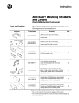
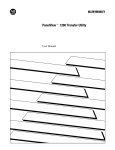
Installation Data
ID
Installing a User EEPROM in a Series D or E
PanelView Terminal
(Cat. No. 2711-NM3)
Description
The PanelView terminal is designed so that you can install an optional user
EEPROM.
An EEPROM can be used as backup for the application file or as 64K of
additional application memory, depending on its configuration in the
PanelBuilder Development Software.
With an EEPROM used for application backup (not as extra application
memory), the application file is automatically copied to the EEPROM
when it is downloaded into the terminal.
For details on configuring the EEPROM for extra application memory, see
the PanelBuilder Development Software User Manual, Chapter 3, Using
PanelBuilder; for more information on programming EEPROMs, see the
PanelBuilder Development Software User Manual, Chapter 6, File
Operations.
ATTENTION: Make sure the power cable is disconnected
before you open a PanelView terminal.
To install a user EEPROM:
1.
Disconnect the power cable, Remote I/O cable, and RS-232 cable.
2.
Take the necessary precautions against electrostatic discharge.
Ideally, you should use an anti-static mat or wear a grounding wrist
strap whenever you work with any electronic components sensitive to
electrostatic discharges.
If you’re not using an anti-static mat or wrist strap, follow these
precautions before you touch any components inside a PanelView
terminal:
assume your body is always carrying an electrostatic charge
frequently touch any grounded metal surface to discharge yourself
Installation Data
Installing a User EEPROM
wear cotton clothes, not wool or synthetic fabrics
don’t move too much or scuff your feet when walking on carpets
be extra careful in low-humidity environments
ATTENTION: The electronic components in the PanelView
terminal are extremely sensitive to static electricity and may be
permanently damaged by electrostatic discharges.
3.
Open up the PanelView terminal logic drawer. Remove the two
screws located near the bottom back of the unit to drop the tray
containing the board.
Figure 1
Opening the Series D or E PanelView Terminal
........
......
Color Back Panel
Remove these
two screws to access
the logic board.
........
......
Monochrome Back Panel
21171
2
4.
Socket U2 is labeled User Memory as shown in Figure 2.
5.
Set the jumpers JP1 and JP2 to the right-most pins, labeled
EPROM/EEPROM (as shown in Figure 2).
Installation Data
Installing a User EEPROM
Figure 2
PanelView Series D or E Logic Board, with Jumpers JP1 and JP2 in the
EPROM/EEPROM Position
SYSTEM MEMORY
Node Adapter Firmware
System Firmware
User PROM
U2
USER MEMORY
JP2
JP1
20319
6.
Gently ease the chip’s pins into the socket.
ATTENTION: The notch on the chip MUST be on the same
end as the notch on the socket.
When all the pins are properly positioned in their holes, and the notch
is on the correct side, gently press the chip into the socket. It will go
in easily if the pins are properly positioned.
ATTENTION: If you break or severely bend a pin, the chip
will be unusable.
7.
Close the PanelView terminal and fasten the screws, then reconnect
the Remote I/O cable, RS-232 cable and power cable.
3
Installation Data
Installing a User EEPROM
8.
Verify that the PanelView terminal is working properly:
a.
Connect power to the terminal.
b.
Set the terminal to Configure mode and check the User
EPROM/EEPROM Power-up Test setting. Set it to Yes.
c.
Disconnect and reconnect power to the terminal.
d.
If the following message appears, the EEPROM has not been
installed properly, is corrupted, or has not been programmed:
Figure 3
EPROM/EEPROM Minor Fault Message
Clear
20200
If this message appears, consider the following points and repeat the
installation procedure if necessary:
make sure that the chip is seated properly in its socket and that no
pins are bent
make sure that the notch on the chip is on the same end as the
notch on its socket
Allen-Bradley has been helping its customers improve productivity and quality for 90 years.
A-B designs, manufactures and supports a broad range of control and automation products
worldwide. They include logic processors, power and motion control devices, man-machine
interfaces and sensors. Allen-Bradley is a subsidiary of Rockwell International, one of the
world’s leading technology companies.
With major offices worldwide.
Algeria • Argentina • Australia • Austria • Bahrain • Belgium • Brazil • Bulgaria • Canada • Chile • China, PRC • Colombia • Costa Rica • Croatia • Cyprus • Czech
Republic • Denmark • Ecuador • Egypt • El Salvador • Finland • France • Germany • Greece • Guatemala • Honduras • Hong Kong • Hungary • Iceland • India •
Indonesia • Israel • Italy • Jamaica • Japan • Jordan • Korea • Kuwait • Lebanon • Malaysia • Mexico • New Zealand • Norway • Oman • Pakistan • Peru • Philippines
• Poland • Portugal • Puerto Rico • Qatar • Romania • Russia–CIS • Saudi Arabia • Singapore • Slovakia • Slovenia • South Africa, Republic • Spain • Switzerland •
Taiwan • Thailand • The Netherlands • Turkey • United Arab Emirates • United Kingdom • United States • Uruguay • Venezuela • Yugoslavia
World Headquarters, Allen-Bradley, 1201 South Second Street, Milwaukee, WI 53204 USA, Tel: (1) 414 382-2000 Fax: (1) 414 382-4444
Publication 2711-2.3—June 1993
Supersedes
Publication 2711-2.3 Dated December 1992
4
40061-192-01 (B)
E 1993 Allen-Bradley Company Printed in USA


![[The Title of Document Property show here]](http://vs1.manualzilla.com/store/data/005679617_1-26050dab619968a0ccd4ef0aac394c5d-150x150.png)