1
llllllllllllllllllllllllllllllllllllllllllllllllllllllllllllllllllllllllll
USOO5598409A
United States Patent [19]
[11] Patent Number:
Madonna et al.
[45]
Date of Patent:
1/1990
4/1987
3/1990
Jan. 28, 1997
[54]
PROGRAMMABLE
TELECOMMUNICATIONS SWITCH FOR
PERSONAL COMPUTER
0350402
3534918
0358597
4101885
7/1992
Germany .
[75]
Inventors: Robert P. Madonna, W. Barnstable;
58'69193
4,1983
Japan '
Robert J. Buttell, Pocasset; Mark P.
Hebert, Kingston, all of Mass.
‘
5,598,409
European Pat. Off. .
Germany Germany .
OTHER PUBLICATION
_
S
“Travels,” Andy, Marc and Harry, Teleconnect vol. 5 Issue
[73] Assignee: Excel, Inc., Hyannis, Mass.
11 pp_ 3940
IEEE International Conference On C0mmunications-—ICC
[21] Appl. No.: 651,123
[22] Filed:
May 21, 1996
1990—-Paper 211.3 vol. 1, 15 Apr. 1990, Atlanta, (US) pp.
128-133 XP14739°~
Brochure for Model PCX~384 PC Digital Switching
Exchange, manufactured and sold by Excel, Inc., Sagamore
Related US. Application Data
Beach, MA. Undated.
[63] 5311133152225;5:551:56iss‘lé?gffféféglf?aebglffggi
User’s Manual for Model PCX-384 PC Digital Switching
abandoned, which is a continuation of Ser. No. 953,690,
Exchange Undated
Sep. 29, 1992, Pat. No. 5,321,744.
[51] Int C16
H04M 3/00_ H04M 302
.
.
............................ ..
,
I
Primary Examiner—Th0mas W. Brown
I
Assistant Examiner_Daniel S_ Hunter
[52] US. Cl. ........................ .. 370/364, 379/269, 337796238746,
[58]
Attorney, Agent, or Firm_CeSari and McKenna
Field of Search ............................ .. 379/88, 201, 268,
379/269, 279, 218, 225, 284; 370/583,
[57]
58.2
_
[56]
ABSTRACT
Auser-programmable telephone switch which resides within
a commercially available personal computer. The switch is
References Clted
controllable by either the personal computer’s microproces
U'S' PATENT DOCUMENTS
provided within the switch. The switch includes a CPU/
sor or a separate, external host connected to an interface
4,009,337
2/1977 Sakai et a1. ........................... .. 379/122
4,228,536 10/1980 Gueldenpfennig et a1. .
et
matrix card that contains a time slot interchange and a CPU
370/66
running under a real time operating system_ The CPU/matrix
......... ..
27322136
211/1988 Molnar """" '
4’ggs’gsg
glissziiwgzg '
card controls the overall operation of tha Switch in accor.
' ' ' ' "337/92/
dance with messages received from the operative host. In
‘579H912 X
general, those tasks or functions which must be performed
4’916’726
4,1990 M orley Jr et'
379,218 X
in real time are the responsibility of the switch, as opposed
4:955:054
9/1990 Boyd, in n a1.
2.... 379/269
to the internal or external 11°89 within the Switch, certain
4,993,017
5,007,080
5,014,269
2/1991 Bachinger et a1_ 0
__ 370/582
4/1991 MacMillan et al. .
379/269
5/1991 Picandet ............................. .. 370/8511
tasks or functions may be delegated by the CPU/matrix card
to intelligent line cards which contain their own micropro
cessors having substantial call processing caP ability.
FOREIGN PATENT DOCUMENTS
0192894
9/1986
European Pat. O?‘. .
28 Claims, 4 Drawing Sheets
r ————————————————— “ “ — *1
remain: n
|
|
I BATTERY/RINGI
i
gene _[
DISK
e
,
I|
—h‘
: _e(,
i I
i
C?’
[8
PCl/OBUS
(9
Pc POWER BUS
———
i
{-
43
—
CPU/
—
—
C§Q
i Mcqgolx
L‘ _ _ T “ _ _ _ “'_"l
—
—
Ylzii'cg”
I
:
—-
*i‘“_E£”__]
J—
|
J",
—
—
DIGITAL
I
-———-~——-—-||
I4
TERMIN I [
05p
'
CARD |6'\ CARD 1% £3: E i
20
liiotcaus
11-
II
32 : lI
l‘___"'
[22
24
TDMICONTROLBUS
BUS
Hi1,‘
J I||I
LCST
‘,
{ “Lain
: |
[26
TIMINQICUSNTROL BUS
n _ _ _ _ ,4
' |———1
30
|
I
ANALOG
I ' Lolfs
.
‘ 1,
| |
| |
| [
ANALOG
2 11838123" “8
I I
I iTRUNKS .-
I
:I
| |
|
BATTERY/RING VOLTAGEZBBUS
I l
[ Ls‘im" ___________ ._ _ _l :
2N.
_
_
_
E _
_
_
_
_
_
_
_ _
_
_
_
w
_
__
4
US. Patent _
Jan. 28, 1997
Sheet 4 of 4
5,598,409
L
,\
mm
m405a28q;
wzEimkbq
mam0.5:w|~,
mam2Eq.
v6E
Mm6a45m,?
|~Hw
L
0mm4305a2183m5,
||~,QNQ
p
mmm;mamm8aTom,
||.~J®N~
vA
—
.
@E
S
w
d
m
9gPow.6528
.Q
mm
MJ
p
wlTw
aa-
Jd
v
o@3<4z27
.n:
u:
5w3%3w
g
7
was‘;
n
T
TTTT
xmom8oz.wa3hE2j.4
5,598,409
1
2
PROGRAMMABLE
TELECOMMUNICATIONS SWITCH FOR
SUMMARY OF THE INVENTION
In brief summary, the present invention provides a user
PERSONAL COMPUTER
programmable telephone switch which resides within a
commercially available personal computer. The personal
This is a continuation of U.S. Ser. No. 08/350,589, ?led
Dec. 6, 1994 and now abandoned, which is a continuation of
U.S. Ser. No. 08/216,692, ?led Mar. 23, 1994, which is now
abandoned, which is a continuation of U.S. Ser. No. 07/953,
690, ?led Sep. 29, 1992 and issued as U.S. Pat. No.
5,321,744 on Jun. 14, 1994.
computer, which typically runs on a widely used, applica
tion-oriented operating system, provides a platform for
customers that is both easy to program and readily integrat
able into existing communication networks.
The switch is controllable by the personal computer’s
central processing unit (PC CPU), a motherboard or plug-in
PC CPU, any of which may act as an “intemal” host.
Alternatively, the switch is controllable by a separate, exter
nal host connected to an interface provided within the
switch.
When an internal host is used, all real time call processing
is handled by the switch independent of the internal host.
None of the internal host’s resources (microprocessor,
memory, disk, etc. ) is needed to execute time-critical, real
BACKGROUND OF THE INVENTION
1. Field of the Invention
The present invention relates generally to the ?eld of
telecommunications and, more speci?cally, to a program
mable telecommunication switch which may reside within a
personal computer.
2. Discussion of the Prior Art
User-programmable telecommunication switches are used
in a wide variety of applications such as voice messaging,
telemarketing services and the like. A programmable switch
is usually controlled by a host device, which is typically a
computer that runs an application program. A customer may
either purchase a commercially available application pro
gram that is compatible with the host and switch hardware
time tasks. Thus, all of the internal host’s resources are
20
When an external host is used, none of the internal host’s
resources is needed to control the switch or perform real
time call processing tasks. The external host’s resources are
available for use by the application program and the internal
25 host may be used for a completely different application or,
alternatively, held in reserve as a back-up should the external
host fail. Also, when an external host is used, all that is
or may elect to write a custom program.
As the application program runs, the host issues instruc
tions to the switch by way of a communication channel. The
available for use by the application program.
30
required to make the switch operable is a passive backplane
for supplying electrical power.
Physically, the switch comprises a plurality of circuit
switch responds to these instructions by taking appropriate
boards or cards which are dimensioned to ?t within the
action, which may include issuing a response to the host to
con?rm- receipt or execution of the instructions.
chassis of the personal computer. A CPU/matrix card con
Conventional programmable switches exhibit several dis
advantages which unduly limit their utility in many appli
tains a time slot interchange and a central call processor
35
(microprocessor) running under a real time, multi-tasking
operating system. The CPU/matrix card, which includes
circuitry for selecting either the internal host or external host
cations. For example, a conventional switch that requires its
to control the switch, conducts all communication with the
host device to become involved with call processing tasks
host. The CPU/matrix card performs or delegates to other
that must be performed in “real time” creates a signi?cant
intelligent cards within the switch the performance of all real
processing burden on the host. The term “real time” is used
40 time call processing tasks, thus freeing the host from
herein to refer generally to call processing (e.g., sending or
involvement in any real time tasks.
receiving digits) or other tasks which must be executed
within a time period on the order of tens of milliseconds. If
Four busses provide communication paths between the
the host is running under an operating system, such as
CPU/matrix card and other cards within the switch: a
timing/control bus; a line card status/control bus; a time
DOS® or UNIX®, which is user or application-oriented and 45
not designed for real time operation, the real time demands
made by the switch will tend to monopolize the host’s
division multiplex (TDM) bus for carrying pulse coded
modulation (PCM) voice tra?ic and analog line signalling;
processing resources. This may, in turn, force the customer
and an HDLC or interprocessor bus. A ?fth bus, the battery/
to undesirably limit the amount of tra?ic through the switch
ring voltage bus, is connected only to line cards which
so that the host can maintain control.
This problem is not satisfactorily solved by simply install
50
terminate analog lines or trunks. These ?ve busses are used
exclusively by the programmable switch and do not interfere
with communications within the internal host, such as those .
ing a real time operating system on the host. This is because
the multitude of real time call processing tasks generated by
between the PC CPU and disk controllers, video graphics
cards, serial or parallel ports or LAN controllers.
a switch having a few hundred ports would still occupy so
Digital (T1) line cards are provided for terminating digital
much of the host’s resources that the application program 55
lines or trunks. Each digital line card includes its own
could not run properly. Moreover, most corrunercially avail~
microprocessor which, under instructions from the CPU/
able computers which could be used as hosts do not operate
on any widely used real time operating system. Prospective
customers express a strong preference, if not an absolute
demand, for a host operating system that is widely used and
represents no signi?cant barrier to developing custom appli
cations software.
Another disadvantage of conventional programmable
60
matrix card, may be used to perform certain real time call
processing tasks on board the line card. Digital line cards
communicate with the CPU/matrix card over the HDLC bus.
Analog line cards are provided for terminating analog
lines or trunks. Each analog line card may be con?gured
with, different modules to terminate lines or trunks having
different types of signalling protocols on the same card.
Other optional cards, such as a digital signal processor
switches is that they can only be connected to one host at a
time. This means that should the host malfunction or fail, the 65
switch will not be controllable and service will be impaired
(DSP) card, may be incorporated into the switch to provide
or completely lost.
desired services or features.
5,598,409
3
4
In accordance with one aspect of the present invention,
tasks are architecturally divided according to whether they
require real time processing. Those tasks which must be
performed in real time are the responsibility of the switch,
cessor bus 20; a TDM bus 22; a line card (LC) status/control
bus 28 supplies battery voltage (48 VDC) and ringing
as opposed to the internal or external host. Further, within
card 19 serves to physically terminate busses 20, 22, 24, 26
and 28.
bus 24; and a timing/control bus 26. A battery/ring voltage
voltage (109 VAC) to the analog line card 18. The terminator
the switch, certain tasks or functions may be delegated by
the CPU/matrix card to, for example, digital line cards
which contain their own microprocessors having substantial
call processing capability. This process of delegation is
carried out automatically and transparently to the host.
Consequently, the host is relieved of dealing with real time
The line cards 14 and 18 and the DSP card 16 are all
connected to and receive their basic operating power from
the PC power bus 9. Although only one digital line card 14
and one analog line card 18 are depicted, it should be
understood that additional line cards of either type may be
added subject to two physical limitations: (1) the maximum
tasks, which tend to reduce efficiency and processing speed,
switching capacity of the CPU/matrix card 12, and (2) the
and the CPU/matrix card is relieved of dealing with tasks
pertaining to digital ports that are within the capability of a
physical space within the chassis of the PC 2.
An external host 30, which may comprise a separate
personal computer, workstation or other computer, may
optionally be connected via a communication channel 32 to
the CPU/matrix card 12. The CPU/matrix card 12 preferably
includes a conventional RS-232 compatible interface for
connecting the channel 32. The external host 30 preferably
digital line card’s processor.
Another advantage of the present invention is the high
speed of host-to-switch messaging between the personal
computer motherboard and the switch which resides
thereon. This high messaging speed is achieved by using the
standard personal computer bus as the communication chan 20 operates under an application~oriented operating system.
nel between the internal host and the CPU/matrix card.
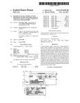
If desired, the switch 10 can reside on a passive backplane
(no PC CPU 4 or disk 6 present) from which its receives
BRIEF DESCRIPTION OF THE DRAWINGS
electrical power and be controlled by the external host 30.
This invention is pointed out with particularity in the
appended claims. The above and further advantages of this
invention may be better understood by referring to the
following description taken in conjunction with the accom~
25
An external battery/ring voltage supply 31 is connected
via a path 33 to the terminator card 19. Supply 31 may
comprise, for example, a commercially available power
supply.
FIG. 2 shows the CPU/matrix card 12 in greater detail. A
central
call processor 34 is connected to both the HDLC bus
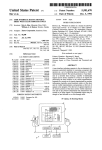
FIG. 1 is a block diagram of a programmable telecom 30 20 and the LC status/control bus 24. The central call
panying drawings, in which:
munications switch which resides in a personal computer
and which is constructed in accordance with a preferred
embodiment of the present invention;
FIG. 2 is a detailed diagram of the CPU/matrix card of
processor 34 is also connected with host select circuitry 35,
random access and read only memories 36, watchdog timing
circuitry 38, input/output (I/O) control circuitry 40, timing
and control/select circuitry 42 and a time slot interchange
35
FIG. 1;
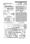
FIG. 3 is a detailed diagram of the digital line card of FIG.
(TSI) 44. Timing and control/select circuitry 42 is connected
to the TSI 44, the timing/control bus 26 (for loop timing) and
to three sources of timing signals, which are denoted REF 1,
REF 2 (which may be supplied by external sources for
reference timing) and OSCILLATOR (which may be sup
plied by a free running oscillator located on the CPU/matrix
1; and
FIG. 4 is a detailed diagram of the analog line card of FIG.
1.
card 12), respectively.
DETAILED DESCRIPTION OF AN
ILLUSTRATIVE EMBODIMENT
The central call processor 34, which is preferably a
Motorola 68302 microprocessor, has control over all of the
FIG. 1 shows a commercially available personal computer 45 other circuitry on the CPU/matrix card 12. The central call
processor 34 preferably runs under a real time operating
(PC) 2 which includes a PC central processing unit (CPU) 4
system such as pSOS®, sold by Integrated Systems, and
and a hard disk drive 6 interconnected by a PC input/output
preferably uses Q.93l-1ike messages, a CCITT standard
(I/O) bus 8 and a PC power bus 9. The PC 2 is preferably a
protocol, for communicating over the HDLC bus 20. Using
PC~AT®, sold by International Business Machines, or a
compatible thereof. Other personal computers having more 50 the HDLC bus 20, the central call processor 34 may transmit
a message simultaneously to all cards connected to that bus.
memory or more powerful CPUs than the PC-AT® may also
The processor 34 may use the LC status/control bus 24 to
be used. The PC 2 preferably operates under an application
select a particular card to transmit a message over the HDLC
oriented operating system, such as DOS® or UNIX®.
bus 20.
The PC 2 consists of a chassis or housing in which a
The host select circuitry 35, which is preferably a switch,
motherboard is mounted, along with the disk drive 6 and
other optional assemblies such as ?oppy disk drives,
operates to inform the processor 34 whether to communicate
with the internal hot or the external host upon power-up.
modems and the like. The PC CPU 4 is mounted on the
motherboard, which includes a series of “slots” into which
110 control circuitry 40, which manages all communica
tion between the central call processor 34 and the internal
host, preferably appears as a COMM port or other standard
PC I/O port on the PC I/O bus 8.
other boards (cards) may be inserted and thereby connected
to the PC 110 and power busses 8 and 9.
A programmable telecommunication switch 10 resides
within the PC 2. A CPU/matrix card 12 is inserted into one
of the slots on the motherboard and thus connected to the
busses 8 and 9. The CPU/matrix card 12 is interconnected
with a digital (T1) line card 14, a digital signal processing
(DSP) card 16 and an analog (universal) line card 18 and a
terminator card 19 by four busses: an HDLC or interpro
Timing and control/select circuitry 42, as described fur
ther below, operates in response to instructions from the
central call processor 34 to select one of ?ve available
65
signals for synchronizing the CPU/matrix card 12. Two such
signals are provided by the timing/control bus 26, the other
three being REF 1, REF 2 and OSCILLATOR.
5,598,409
5
6
T81 44, which is preferably a 512 port non-blocking
matrix, receives incoming PCM voice data via the TDM bus
22 (time slots) and operates, as directed by the central call
host or the external host may be made using messages
between the host and switch 10.
processor 34, to reorder the time slots and direct them over
the bus 22 to the appropriate destinations.
Following a successful download of con?guration infor
mation, all such information is preferably stored in random
5
access memory 36 on the CPU/matrix card 12. The memory
FIG. 3 shows the digital line card 14 of FIG. 1 in greater
36 is preferably provided with battery-backup in order to
detail. The line card 14 includes a line card processor 46
which is connected with the HDLC bus 20, random access
preserve the con?guration information and eliminate the
need for re-downloading in the future should the switch 10
experience a power loss.
and read only memories 48, digital select circuitry 50,
HDLC select circuitry 51, elastic stores 52a-52n, dual
framers 54a-54n and dual T1 interfaces (IF) 56a—_56n.
Timing and control circuitry 54 is connected to the timing
and control bus 26, identi?cation (ID) circuitry 49, the
digital select circuitry 50, the elastic stores 52a-52n, the
The con?guration information typically includes basic
instructions as to how to control each type of port that the
switch may have. Such instructions are stored in memory 36
on the CPU/matrix card 36 for all analog ports, but are
downloaded and stored in memory 48 on the digital line card
dual framers 54a-54n and the dual T1 interfaces 5641-5611.
15 14 for digital ports, as described below. Such information
Line card processor 46, which is preferably a Motorola
also preferably includes synchronization priority informa
68302 microprocessor, has control over the other circuitry
tion which speci?es an order in which the ?ve possible
on line card 14. Processor 46 communicates with the central
synchronization signals available to the timing and control/
call processor 34 on the CPU/matrix card 12 by exchanging
select circuitry 42 should be used to synchronize the CPU/
messages over the HDLC bus 20. HDLC select circuitry 51, 20 matrix card 12.
under the control of processor 46, is responsible for con
At this point, the central call processor 34 proceeds to
trolling the transmission of messages by the line card 14
interrogate all other cards present within the switch 10. The
over the HDLC bus 20.
processor 34 uses the LC status/control bus 24 to interrogate
Digital select circuitry 50 is responsible for moving PCM
tra?ic between the TDM bus 22 and the elastic stores
52a—52n. On the digital line card 14, the PCM tra?ic
represents only voice, tone or data and does not include any
25
all line cards, both digital and analog, and to receive
responses from their respective ID circuitry. These responses
indicate to the processor 34 what types and the number of
line cards present.
Subsequently, the central call processor 34 will further
line signalling information.
Each dual T1 interface 56a—56n is capable of terminating
interrogate the identi?ed analog line cards 18, again using
the LC status/control bus 24. In responding to this further
two T1 spans, thus providing a maximum of 96 D80 ports, 30 interrogation, the analog interfaces 62a—62n identify the
out of the total of 512 ports available on the CPU/matrix
types of ‘modules (signalling protocols) they represent, the
card 12, per digital line card 14.
number of modules, etc. This information is retained in the
Turning now to FIG. 4, analog line card 18 includes
memory 36 on the CPU/matrix card 12.
timing and control circuitry 58, which is connected to the LC
Similarly, the central call processor 34 further interrogates
status/control bus 24, the timing/control bus 26, digital
select circuitry 60 and identi?cation (ID) circuitry 64, which
is similar to ID circuitry 49 of FIG. 3. Digital select circuitry
35
the digital line card 14 responds with a message indicating
60 is connected to analog interfaces 62a—62n. LC status/
control bus 24 and battery/ring voltage bus 28 are connected
to each analog interface 62a—62n.
the line cards status, how many ports are provided on the
card and other information such as whether a download of
basic instructions is needed. If a download is needed
Timing and control circuitry 58 communicates with the
(requested by the line card 14), the central call processor 34
central call processor 34 on CPU/matrix card 12 via the LC
will respond by passing the appropriate information, previ
status/control bus 24.
Digital select circuitry 60 is responsible for moving PCM
tra?ic between the TDM bus 22 and the analog interfaces
62a—62n. In contrast with the digital line card 14, the PCM
traffic between the analog line card 18 and the TDM bus may
also contain line signalling information such as on-hook/
off-hook, in addition to voice, tone signalling (in-band
signalling) or data.
identi?ed digital line cards 14 using the HDLC bus 20. The
processor 34 transmits a message via the HDLC bus 20 and
45
ously received from the host, to the line card processor 46
via the HDLC bus 20.
Once all cards present have been identi?ed and interro
gated by the central call processor 34, that processor (using
memory 36) constructs a map or table which includes the
PCM address range, type of line card and status and type of
50
each port within the switch 10. In addition, if a digital line
card 14 is identi?ed, the central call processor 34 will
Analog interfaces 62a~62n are preferably separate physi
proceed to delegate appropriate call processing tasks to that
cal modules which may be individually installed on the
analog line card 18. Such separate modules may support
present invention, such delegated tasks include signalling
different signalling protocols, thereby advantageously
line card’s processor 46. In a preferred embodiment of the
55
allowing different types of trunks to be terminated on a
single analog line card 18.
With reference now to FIGS. 1-4, the operation of the
programmable switch 10 will be described. When the switch
10 is initially powered up (i.e., the PC 2 is turned on), basic
con?guration information and operational system software
60
must be downloaded from a host before initialization pro
cedures or any call processing operations may commence.
The CPU/matrix card 12 knows whether to request a down
load from the internal host or the external host based on the 65
setting of the host select circuitry 35. After a successful
download is completed, the selection of either the internal
supervision, call inpulsing and outpulsing, instruction con
trol and management, detection of incoming calls and gen
eration of outgoing calls.
At this point, the switch 10 is ready to begin normal
operation in accordance with messages received by the
CPU/matrix card 12 from the host and activity at the ports.
The foregoing description has been limited to a speci?c
embodiment of this invention. It will be apparent, however,
that variations and modi?cations may be made to the inven
tion, with the attainment of some or all of the advantages of
the invention. Therefore, it is the object of the appended
claims to cover all such variations and modi?cations as
come within the true spirit and scope of the invention.
5,598,409
8
7
a personal computer motherboard, including,
What is claimed and desired to be secured by Letters
Patent of the United States is:
1. A programmable communications switch system com
an input/output bus, and
a power bus,
prising:
wherein said switching means is connected to both of said
busses.
4. The switch system as in claim 3 wherein said program
a personal computer including,
a time slot interchange,
a central call processor con?gured to perform real-time
call control processing functions on said time slot
mable communications switch further comprises:
one or more line cards, connected in communicating
interchange, and
10
an internal host computer having a ?rst application
oriented operating system to run communications
applications that control said central call processor;
and
an external host computer having a second application
oriented operating system to run communications
applications that control said central call processor;
a host selector coupled to said central call processor,
con?gured to select one of said internal and external
host computers to control said central call processor,
wherein said call control processor pertbrrns all real-time
call control processing in response to commands from
said selected host computer,
wherein said selected host computer controls said central
call processor exclusively of said non-selected host 25
computer.
2. A programmable communications switch system com
prising:
a personal computer including,
a programmable communications switch, including,
controllable~switching means for performing real
35
means for processing said predetermined messages,
40
said communications switch;
an external host computer having a second application
oriented operating system and being programmable to
generate said predetermined messages to control said
communications switch;
means for interfacing said switching means with said
external host computer; and
50
host select means, coupled to said message processing
means, for selecting one of said internal or external host
computers to control said controllable-switching
means,
55
call processing tasks, while retaining responsibility for per
forming such tasks with respect to said analog line cards.
7. The switch system as in claim 2 further comprising:
means, responsive to the message processing means, for
selecting one of a plurality of synchronization signals
available thereto.
8. A programmable communications switch system com
cation paths established between various ones of a
a real time operating system;
a ?rst host computer having a ?rst application-oriented
operating system to an communications applications
that control said switch;
a second host computer having a second application
oriented operating system to run communications
applications that control said switch;
means for interfacing said communications switch with
the second host computer; and
host selector, coupled to said central call processor, con
?gured to select one of said ?rst and second host
computers to control said communications switch,
wherein all real-time call control processing is managed
by said central call processor and wherein when said
?rst host computer is selected to control said commu
nications switch said ?rst host computer runs commu
nications applications that control said switch exclu
sively of said second host computer and wherein when
nal host computer is selected to control said commu
nications switch, said internal host computer runs com
60
said second host is selected to control said communi
cations switch, said second host computer runs com
munications applications that control said communica
tions switch exclusive of said ?rst host computer.
9. The system as in claim 8, wherein said ?rst host
when said external host is selected to control said
host computer comprises:
cessing means for performing one or more predetermined
sages, including,
to generate said predetermined messages to control
3. The switch system as in claim 2 wherein said internal
distinguish between said one or more line cards and may
assign responsibility to said digital line card message pro
a time slot interchange, and
oriented operating system and being programmable
communications switch, said external host computer
controls runs communications applications that control
said communications switch exclusive of said internal
host computer.
switching means.
6. The switch system as in claim 5 wherein said message
processing means of said switching means is operable to
plurality of ports within said switch, said central
call processor responsive to predetermined mes
including,
munications applications that control said switch
exclusively of said external host computer and wherein
second means for processing messages generated by said
a central call processor con?gured to perform real
time call control processing related to communi
cation paths between various ones of a plurality of
wherein all real-time call control processing is managed
by said switching means and wherein when said inter
comprises;
a personal computer including,
a programmable communications switch, including,
dynamically connecting or disconnecting communi~
a time slot interchange, and
a real time operating system;
an internal host computer, having a ?rst application“
either digital or analog lines or trunks.
5. The switch system as in claim 4 wherein each of said
one or more line cards for terminating digital lines or trunks
prising:
time call-control processing functions including
ports in response to predetermined messages,
relationship with said switching means, for terminating
computer further comprises:
65
a personal computer motherboard which includes an
input/output bus and a power bus and said communi
cations switch is connected to both of said busses.
5,598,409
9
10
10. The system as in claim 9 further comprising;
number of signaling protocol modules located on said ana
one or more line cards, connected in communicating
relationship with said central call processor, said one or
log line card.
19. The system as in claim 10 wherein said digital line
cards are connected in communicating relationship with said
central call processor by a bus for carrying messages bidi
rectionally, a bus for carrying time division multiplex data,
more line cards being of a ?rst type for terminating
digital lines or trunks, or of a second type for tenni
nating analog lines or trunks.
11. The system as in claim 10 wherein each of said one or
and a timing/control bus.
20. The system as in claim 10 wherein a second message
processor of each of said digital line cards transmits one or
more messages to said message processor of said central call
processor which indicates the status of the digital line card.
21. The system as in claim 20 wherein said second
more line cards for terminating digital lines or trunks
comprises:
means for processing messages generated by said central
call processor.
12. The system as in claim 11 wherein said central call
processor is operable to distinguish between said one or
more line cards and may assign responsibility to said digital
message processor of each of said digital line cards transmits
one or more messages to said message processor of said
line card message processing means for performing one or
switch which indicates the types of ports provided by the
digital line card.
more predetermined real~time call processing tasks, while
retaining responsibility for performing such tasks with
respect to said analog line cards.
22. The system as in claim 20 wherein said second
message processor of each of said digital line cards transmits
13. The system as in claim 8 wherein said switch further
comprises:
20
timing selector, responsive to said central call processor,
for selecting one of a plurality of synchronization
signals available thereto.
one or more messages to said message processor of said
switch which indicates how many ports are provided on the
digital line card.
23. The system as in claim 20 wherein said second
message processor of each of said digital line cards transmits
14. The system as in claim 10 wherein said second host 25 one or more messages to said message processor of said
switch which indicates whether a download of instructions
computer is connected with said interfacing means and
exclusively controlling said central call processor without
is needed by the digital line card.
said ?rst host computer.
24. The system as in claim 17 wherein said message
processor of said central call processor, in response to
15. The system as in claim 8, wherein said messages are
generated by said ?rst and second host computers in accor
dance with a predetermined format which is independent of
the types of line cards that are included in said communi
cations switch.
16. The system as in claim 10 wherein said analog line
cards are connected in communicating relationship with said
central call processor by a bus for carrying time division
multiplex data, a timing/control bus and a line card status/
control bus.
17. The system as in claim 10, wherein said switch further
comprises a message processor for receiving and processing
said predetermined messages, and further wherein each of
35
call inpulsing and outpulsing.
27. The system as in claim 17 wherein said message
processor of said central call processor downloads instruc
tions to said digital line card which include instructions for
interrogation by said message processor by identifying one
detection of incoming calls.
or more types of signaling protocol modules located on said
18. The system as in claim 10, wherein said switch further
comprises a message processor for receiving and processing
said predetermined messages, and further wherein each of
said analog line cards includes means for responding to an
interrogation by said message processor by indicating the
signalling supervision.
26. The system as in claim 17 wherein said message
processor of said central call processor downloads instruc
tions to said digital line card which include instructions for
said analog line cards includes means for responding to an
analog line card.
receiving a message from a digital line card indicating that
a download of instructions is needed, downloads instruc
tions to said digital line card.
25. The system as in claim 17 wherein said message
processor of said central call processor downloads instruc
tions to said digital line card which include instructions for
45
28. The system as in claim 17 wherein said message
processor of said central call processor downloads instruc
tions to said digital line card which include instructions for
generation of outgoing calls.
*****


![mm [mm [1 um um [11115151116 |])|]1]](http://vs1.manualzilla.com/store/data/005839409_1-1dd2adaaab9a040f039445848c9c3135-150x150.png)