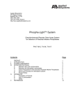
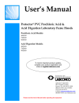
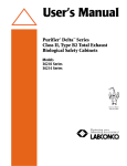
1
User’s Manual
LabShield
®
By CampbellRhea ®
Laboratory Fume Hoods
Air Foil By-Pass Models:
6714, 6716, 6718
ADA Models:
8796, 8798, 8800
Demonstration Hood
6725G
CampbellRhea
1865 North Market Street Paris TN 38242
731.642.4251 Fax: 731.642.4262
e-mail: [email protected]
website: www.campbellrhea.com
Copyright Information
All rights reserved.
Contacting
Contact the following for information concerning; freight damage, warranty and
parts, etc.
Project Managers
Wayne Cathey , Director of Engineering
Brian Webb, Engineer
Bobby Veazey, Senior Project Manager
731-642-4251 Ext. 323
731-642-4251 Ext. 288
731-642-4251 Ext. 232
Part #9933700, Rev. D, ECO F109
Chapter 1: Introduction
3
TABLE OF CONTENTS
CHAPTER 1: INTRODUCTION
About This Manual
1
2
CHAPTER 2: PREREQUISITES
Location Requirements
Support Requirements
Exhaust Requirements
Electrical Requirements
Service Line Requirements
3
3
4
4
4
4
CHAPTER 3: GETTING STARTED
Removing the Shipping Skid
Sash Weight Release – ByPass & ADA
Sash Weight Release – Demonstration Hood
Install the LabShield Hood on a Supporting Structure and
Work Surface
Connecting to the LabShield Hood Exhaust System
Connecting the Electrical Supply source to the LabShield
Fume Hood
Connecting the Service Lines to the LabShield Fume Hood
Sealing the LabShield Fume Hood to the Work Surface
Certifying the LabShield Fume Hood
5
5
6
6
8
10
10
10
CHAPTER 4: USING YOUR LABSHIELD FUME HOOD
Operating the Vertical-Rising Sash
Operating the A-Style Combination Sash
Operating the Blower
Operating the Lights
Working in your LabShield Fume Hood
12
12
12
13
13
13
6
8
CHAPTER 5: MAINTAINING YOUR LABSHIELD FUME HOOD 15
Routine Maintenance Schedule
15
Routine Service Operations
16
Chapter 1: Introduction
CHAPTER 6: MODIFYING YOUR LABSHIELD FUME HOOD
Installing Work Surfaces
Installing Ceiling Enclosures above the Fume Hood
Installing Rear Panels Behind the Fume Hood
Installing Additional Service Fixtures
Installing Guardian Digital Airflow Monitor or Guardian Jr.
AirflowMonitor
Distillation Grids – Field Installation
Sash Stop Kit – Field Installation
Installing an Electrical Duplex Outlet
17
17
18
18
18
CHAPTER 7: TROUBLESHOOTING
21
APPENDIX A: LABSHIELD FUME HOOD DIMENSIONS
24
APPENDIX B: LABSHIELD FUME HOOD SPECIFICATIONS
27
19
19
20
20
5
CHAPTER 1
INTRODUCTION
Congratulations on your purchase of a LabShield Laboratory Fume Hood. Your
LabShield Laboratory Fume Hood is designed to protect you.
The LabShield Fume Hood has been engineered to provide maximum visibility in a
laboratory, and effectively contain toxic, noxious, or other harmful materials when
properly installed. The LabShield hoods offer many unique features to enhance
safety, performance, and visibility. To take full advantage of them, please acquaint
yourself with this manual and keep it handy for future reference. If you are
unfamiliar with how fume hoods operate, please review Chapter 4: Using Your
LabShield before you begin working in the fume hood. Even if you are an
experienced fume hood user, please review Chapter 5: Maintaining Your LabShield,
which describes your LabShield Hood’s features so that you can use the hood
efficiently.
1
Chapter 1: Introduction
About This Manual
This manual is designed to help you learn how to install, use, and maintain your
laboratory fume hood. Instructions for installing optional equipment on your hood
are also included.
Chapter 1: Introduction provides a brief overview of the laboratory fume hood,
explains the organization of the manual, and defines the typographical conventions
used in the manual.
Chapter 2: Prerequisites explains what you need to do to prepare your site before you
install your laboratory fume hood. Electrical and service requirements are discussed.
Chapter 3: Getting Started contains the information you need to properly unpack,
inspect, install, and certify your laboratory fume hood.
Chapter 4: Using Your LabShield Fume Hood discusses the basic operation of your
fume hood. Information on how to prepare, use and shut down your LabShield Hood
are included.
Chapter 5: Maintaining Your LabShield Fume Hood explains how to perform routine
maintenance on your fume hood.
Chapter 6: Modifying Your LabShield Fume Hood explains how to modify the fume
hood or add accessories.
Chapter 7: Troubleshooting contains a table of problems you may encounter while
using your laboratory fume hood including the probable causes of the problems and
suggested corrective actions.
Appendix A: LabShield Fume Hood Dimensions contains comprehensive diagrams
showing all of the dimensions for the laboratory fume hoods.
Appendix B: LabShield Fume Hood Specifications contains the electrical
requirements for laboratory fume hood. Wiring diagrams are also included.
2
CHAPTER 2
PREREQUISITES
Before you install your laboratory fume hood, you need to prepare your site for
installation. Carefully examine the location where you intend to install your hood.
You must be certain that the area is level and of solid construction. In addition, a
dedicated source of electrical power must be located near the installation site.
Carefully read this chapter to learn the requirements for your installation site:
•
•
•
•
•
•
The location requirements.
The support requirements.
The exhaust requirements.
The electrical power requirements.
The service line requirements.
The space requirements.
Refer to Appendix A: LabShield Fume Hood Dimensions for complete fume hood
dimensions.
Refer to Appendix B: LabShield Fume Hood Specifications for complete laboratory
fume hood electrical and environmental conditions, specifications and requirements.
Location Requirements
The fume hood should be located away from traffic patterns, doors,
windows, fans, ventilation registers, and any other air-handling device
that could disrupt its airflow patterns. All windows in the room should
be closed.
Support Requirements
DO NOT install the fume hood on a cart, dolly, or mobile bench. ALL
LabShield Hood installations must be permanent and stationary. The
supporting structure usually consists of a base cabinet or stand and
chemically resistant work surface.
3
Chapter 2: Prerequisites
Exhaust Requirements
The exhaust duct connection on the Bypass and ADA models has been designed for
12" nominal duct (12.09" OD) to allow for minimum static pressure loss while
operating at 100 fpm face velocities. The 12" diameter exhaust duct also allows for
proper transport velocities away from the hood in the 1000 fpm to 2500 fpm range.
The Demonstration Hood has been designed for a 10" nominal duct (10.09").The
proper exhaust volume and static pressure loss are listed next for each hood model:
Full Open 28" Sash Opening
Hood Model
Airflow Requirements @100 fpm
6714, 8796
730 cfm @ .16" SP
6716, 8798
960 cfm @ .24" SP
6718, 8800
1180 cfm @ .28" SP
6725G
1100 cfm* @ .40" SP
* Sash opening height is only 26" on Pass Thru Hood and only one
sash can be open at one time.
Electrical Requirements
The LabShield Hoods feature internal wiring for the fluorescent light assembly, light
switch and blower switch. A qualified electrician can make connections to all
internal wiring at the single point wiring junction box on top of the hood. Refer to
Chapter 3: Getting Started and Appendix B: LabShield Hood Specifications for the
wiring diagram for proper electrical installation.
Service Line Requirements
All service lines to the laboratory fume hood should be 1/4"outside diameter, copper
(brass for natural gas), except for a coldwater gooseneck 3/8" outside diameter and
equipped with an easily accessible shut-off valve, should disconnection be required.
If the service line pressure exceeds 40 PSI, it must be equipped with a pressure
regulator to reduce the line pressure. Please check with local codes for other
requirements.
4
CHAPTER 3
GETTING STARTED
Now that the site for your laboratory fume hood is properly prepared, you are ready to
unpack, inspect, install, and certify your unit. Read this chapter to learn how to:
• Unpack and move your LabShield Hood.
• Set up the fume hood with the supporting structure and work surface.
• Connect to an exhaust system.
• Connect the electrical supply source.
• Connect the service lines.
• Sealing the LabShield Hood to the work surface.
• Arrange certification of your LabShield Hood.
Depending upon which model you are installing, you may need common plumbing
and electrical installation tools in addition to 5/16", 3/8", 7/16", and 1/2" wrenches,
ratchets, sockets, a nut driver set, a flat-blade screwdriver, a Phillips screwdriver, and
a carpenter level to complete the instructions in the chapter.
The LabShield Hood models weigh between 400 to 800 lbs. (182-363 kg).
The shipping skid allows for lifting with a mechanical lift truck or floor
jack. If you must lift the fume hood manually, follow safe-lifting
guidelines. Normally, the fume hood can be slid off a hydraulic lift table
and be placed into position on top of the work surface. Do not lift by
the front air foil.
Removing the Shipping Skid
LEAVE THE FUME HOOD ATTACHED TO ITS SHIPPING SKID UNTIL
IT IS AS CLOSE TO ITS FINAL LOCATION AS POSSIBLE. MOVE THE
HOOD BY USING A SUITABLE FLOOR JACK, OR BY PLACING A
FURNITURE DOLLY UNDERDNEATH THE SKID. DO NOT MOVE
THE HOOD BY TILTING IT ONTO A HAND TRUCK.
5
Chapter 3: Getting Started
After you verify the fume hood components, move your hood to the location where
you want to install it.
1. Remove the side panels by unscrewing the tamper resistant screws.
2. Find the hardware (bolts, washers, nuts) that attach the fume hood to the
skid and remove the hardware. Some hardware is on the sides and some is
on the back of the fume hood structure.
Sash Weight Release – Bypass and ADA
To protect the fume hood from damage in shipment, the sash weight has been secured
to the back of the fume hood with four (4) screws. Simply remove the screws and
make sure the sash cables are on the pulleys before operation of the sash.
NOTE: THE SASH WEIGHT ITSELF WAS INDIVIDUALLY MATCHED
FOR THIS SPECIFIC HOOD AND SHOULD NOT BE EXCHANGED ON
ANY OTHER UNIT.
Sash Weight Release – Demonstration
Hood
To protect the fume hood from damage in shipment, both sash weights have been
bolted down to the frame. Remove these attachment screws for proper sash weight
operation.
Install the LabShield Hood on a Supporting
Structure and Work Surface
The LabShield Hood is heavy! Use caution when lifting or moving the
unit.
When installing the LabShield Fume Hood onto a chemically resistant work surface
or benchtop, ensure that the structure can safely support the combined weight of the
fume hood and any related equipment. The work surface should be at least as wide as
the hood to properly support it.
The following are instructions for mounting a cross support:
1. Level the base cabinets and the work surface. Work surface should be
placed flush with the back of the fume hood as shown in Figure 3-1.
2. Scribe a line on the wall or back of the base cabinet to locate the support
under the work surface.
3. Mount the support by attaching it to the wall or base cabinet.
6
Chapter 3: Getting Started
4. Place the hood on top of the work surface and cross support.
The work surface should be smooth and durable, such as a chemically resistant epoxy
resin. The surface should be nonporous and resistant to the acids, solvents, and
chemicals used in conjunction with the LabShield Fume Hood. The work surface
should also contain a dished recessed area for containing primary spills.
Figure 3-1
Hood Depth
“B”
33.20"
Dimensions Shown in Inches
Hood Internal
Filler Panel
Depth
Depth
“D”
“E”
24"
8"
Work Surface
Depth
30"
7
Chapter 3: Getting Started
Connecting to the LabShield Hood Exhaust
System
WARNING: The weight of the exhaust
ductwork system must be supported
independently of the hood superstructure. Do
not allow this weight to be supported by the
hood structure as damage to the hood may
occur.
The exhaust connection should be installed by a qualified HVAC
contractor.
The exhaust connection on the Bypass and ADA hoods have been designed for 12"
nominal pipe (12.09" OD) to allow for minimum static pressure loss with proper
transport velocities away from the hood. The exhaust connection on the
Demonstration hood has been designed for 10" nominal pipe (10.09" OD) to allow for
minimum static pressure loss on that hood.
The selected exhaust duct material should match the hood procedures and chemicals
used to ensure compatibility.
Connecting the Electrical Supply Source to
the LabShield Fume Hood
Prior to connecting any electrical wiring to the fume hood structure, refer to the hood
identification plate for the proper electrical requirements of your specific model.
WARNING: The building electrical supply system for
LabShield Hoods should include overload protection.
A switch or circuit breaker should be in close
proximity to the equipment and within easy reach of
the operator. The switch or circuit breaker is to be
marked as the disconnecting device for the equipment.
Consult the NEC-2002 electrical code for proper
installation.
The identification plate, model number, serial number, and electrical connection
boxes are accessible from the front of the fume hood by removing the front panel.
The LabShield Hood is wired for 115 Volt, 60 Hz. Check the I.D. plate behind the
front panel for voltage verification. The number of circuits varies depending on the
model. A qualified electrician terminates all of the electrical connections at the single
point internal junction box for hook-up. The single point internal junction box is used
for the connection of the lights, blower, and duplex outlet, if so equipped. Refer to
the wiring diagram in Appendix B: LabShield Fume Hood Specifications.
8
Chapter 3: Getting Started
Internal Junction
Box
Figure 3-2
All the wiring for the fume hood SHOULD be performed by a licensed
electrician and conform to all local codes. In most cases, the hood will
require the use of shielded conduit to protect the wiring into the hood.
The grounding connection shall not be made to the terminal box cover.
The fluorescent light on the By-Pass and ADA models have been mounted on top of
the top liner panel and is sealed from vapors inside the hood structure. To change the
fluorescent light bulbs in your hood, you must first remove the front panel from the
hood. Next remove the knock out plugs holding down the light fixture and lift up for
access to the bulbs. The fluorescent lights are now fully exposed and ready for
service. While the fixture is in this position, replace the defective bulbs, and
reassemble.
The Demonstration Hood features one vapor-proof incandescent light assembly. To
change the incandescent light bulb, unscrew the vapor light globe and replace the
bulb, then reassemble.
9
Chapter 3: Getting Started
Connecting the Service Lines to the
LabShield Fume Hood
The hoods with service fixtures have been plumbed from the valve to the hose
connector or gooseneck for your installation convenience. The qualified installer
shall provide supply tubing. Tubing can enter the hood from above, through the back,
or through the work surface to make these connections to the service fixtures.
NOTE: Inspect all fittings for leakage. Tighten the fittings slightly if
needed.
CAUTION: Do not use oxygen with any standard
service fixture.
•
•
Air
Cold Water
•
•
Hot Water
• Vacuum
Natural Gas – See caution below
WARNING: Contact CampbellRhea directly
before using any service other than those listed
above in these valves to assure full
compatibility.
CAUTION: Natural gas should be used only in
the service fixture that has been pre-plumbed
with brass tubing. Sulfur content of the gas
could cause deterioration of standard copper
supply lines.
Sealing the LabShield Fume Hood to the
Work Surface
When the hood has been set in place, ducted, wired, and plumbed, it should be sealed
at the work surface to prevent spilled materials from collecting under the walls of the
hood. Materials such as silicone sealants are recommended to seal the hood structure.
Certifying the LabShield Fume Hood
The combination of your laboratory hood, exhaust ductwork, and exhaust blower
gives you the flexibility to change the airflow at the sash opening of your hood. To
determine the actual face velocity at the sash opening, airflow velocity readings will
need to be taken. This should be done across the sash opening of the hood in
accordance with the Industrial Ventilation Manual section on laboratory hoods that
recommends an average face velocity at the sash opening of 80 to 100 feet per
minute.
10
Chapter 3: Getting Started
Your LabShield Fume Hood has been tested at the factory per ASHRAE 110-1995.
All hoods achieve an “as manufactured rating” of less than 0.05 part per million
(ppm) at 4 liters per minute (lpm); AM<0.10 (consult for individual fume hood
ratings). For “field use” ASHRAE testing contact CampbellRhea.
NOTE: Face velocity profiles and smoke testing should be done
periodically to ensure safe performance.
11
CHAPTER 4
USING YOUR LABSHIELD FUME
HOOD
Operating the Vertical-Rising Sash
Because of the LabShield Hood counterbalanced sash mechanism, it will take only a
few pounds of force to move the sash up or down, and you can operate the sash
smoothly with one or two hands positioned any where along the handle. The verticalrising sash may be raised to a maximum 28" operating height on the By-Pass and
ADA hoods. The airflow requirements should be sized for the 28" operating height if
using sash stops then the airflow requirements can be reduced by approximately 40%
at 18" or approximately 50% at 15".
Because the Demonstration Hood features two sashes, only one sash can be opened at
one time for proper operation. The vertical rising sashes may be raised to a maximum
of 26" operating height. The airflow should be sized for a 26" opening with only one
sash open.
Should you try and open both sashes at the same time an audible alarm will activate
until one sash is closed.
Operating the A-Style Combination Sash
Optional hood models have additional energy saving sashes called A-Style
Combination Sashes in place of vertical-rising sashes. These combination sashes
allow the operator to use the hood with sashes either half open horizontally or
vertically to conserve energy. The horizontal sashes are used in normal operating
mode. Optional sets of sash stops can be installed to prevent raising the vertical sash
above the half-open and fully closed positions unless manually defeated by the
operator. The airflow requirements are sized for the 50% open sash condition.
12
Chapter 4: Using Your LabShield Fume Hood
Operating the Blower
Your LabShield Fume Hood utilizes a remote style blower, which can be activated by
turning the blower switch to “ON.”
Operating the Lights
Your LabShield Fume Hood utilizes a factory-wired fluorescent light to illuminate
the hood interior. Simply turn the light switch to “ON” to operate.
Working in your LabShield Fume Hood
Planning
• Thoroughly understand procedures and equipment required before beginning
work.
• Arrange for minimal disruptions, such as room traffic or entry into the room
while the hood is in use.
Start-up
• Turn on fluorescent light and hood blower.
• Slowly raise the sash.
• Check the baffle air slots for obstructions.
• Allow the hood to operate unobstructed for 5 minutes.
• Wear a long sleeved lab coat and rubber gloves. Use protective eyewear.
Wear a protective mask if appropriate.
Loading Materials and Equipment
• Only load the materials required for the procedure. Do not overload the hood.
• Do not obstruct the front air foil, or rear baffle slots.
• Large objects should not be placed close together and spaced above the work
surface to permit airflow to sweep under the equipment.
• After loading the hood, wait one minute to purge airborne contaminants from
the work area.
Work Techniques
• Keep all materials at least 6 inches inside of the sash, and perform all
contaminated operations as far to the rear of the work area as possible.
• Segregate all clean and contaminated materials in the work area.
• Avoid using techniques or procedures that disrupt the airflow patterns of the
hood.
Final Purging
• Upon completion of work, the hood should be allowed to operate for two to
three minutes undisturbed, to purge airborne contaminants from the work area
before shutting down blower.
13
Chapter 4: Using Your LabShield Fume Hood
Unloading Materials and Equipment
• Objects in contact with contaminated material should be surface
decontaminated before removal from the hood.
• All open trays or containers should be covered before being removed from the
hood.
Shutdown
• Turn off the light and hood blower close the sash.
14
CHAPTER 5
MAINTAINING YOUR
LABSHIELD FUME HOOD
Now that you have an understanding of how to work in the fume hood, we will
review the suggested maintenance schedule and the common service operations
necessary to maintain your fume hood for peak performance.
Only trained and experienced certification technicians should perform
some of the service operations after the fume hood has been properly
decontaminated. DO NOT attempt to perform these operations if you are
not properly trained. The wrench icon precedes the service operations
that require qualified technicians.
Routine Maintenance Schedule
Weekly
• Using ordinary dish soap to clean the surface inside of the fume hood, and the
work surface.
• Using an appropriate glass cleaner, clean the sash and all glass surfaces.
• Operate the fume hood blower, noting the airflow velocity through the hood
using a source of visible smoke.
Monthly (or more often as required)
• Determine the actual face velocity through the sash opening of the hood where
the average reading should be at the specified velocity. (Use calibrated
thermal anemometer or other approved apparatus).
• Using a damp cloth, clean the exterior surfaces of the hood, particularly the
front of the hood, to remove any accumulated dust.
• Check all service valves, if so equipped, for proper operation.
• The hood baffles should be checked for blockages behind them to ensure that
the hood is maintaining proper airflow.
• All weekly activities.
15
Chapter 5: Maintaining Your LabShield Fume Hood
Annually
• Replace the fluorescent and/or incandescent light bulbs.
• Have the fume hood recertified by a qualified certification technician. See
Certifying the LabShield Fume Hood in Chapter 3.
• All monthly activities.
Biannually
• The sash assembly or assemblies should be checked to ensure proper
operation and to make sure there are no signs of abnormal wear on the sash
pulleys, cables and clamps.
Routine Service Operations
Front Panel Removal:
1. Remove the two screws on the bottom flange of the front panel.
2. Lift the front panel up and then away from the hood to provide access to the top.
Changing the Fluorescent Lamp:
1.
2.
3.
4.
16
Turn light switch to “OFF.”
Remove knockout plugs at both ends of fluorescent bracket.
Lift fluorescent light fixture up and away from hood to access bulbs.
Reverse this process to reinstall fluorescent light fixture (replace the knockout
plugs).
CHAPTER 6
MODIFYING YOUR LABSHIELD
FUME HOOD
There are several ways to modify the fume hood for your individual requirements.
These include the addition of work surfaces, service fixtures, air monitor, distillation
grids, electrical duplex outlets, ceiling enclosures, and rear panels. Contact
CampbellRhea for Part Numbers and Pricing.
Installing Work Surfaces
Your LabShield Fume Hood requires a work surface to work properly.
Figure 6-1
17
Chapter 6: Modifying Your LabShield Fume Hood
Installing Ceiling Enclosures above the
Fume Hood
Your LabShield Fume Hood has mounting holes to accept a ceiling enclosure to close
off the area between the top of the hood and the ceiling.
Figure 6-2
Installing Rear Panels Behind the Fume
Hood
Your LabShield Fume Hood can be modified to add a rear panel behind the fume
hood when the fume hood is placed on an island.
Installing Additional Service Fixtures
Additional service fixtures can be installed in the available service fixture holes in
both sidewalls and corner posts. The fume hood is factory set to accept up to four
valves per side.
Figure 6-3
Knob
18
Figure 6-4
Valve
Figure 6-5
Hose Connector
Chapter 6: Modifying Your LabShield Fume Hood
Installing Guardian™ Digital Airflow
Monitor or Guardian™ Jr. Airflow Monitor
The Guardian Digital Airflow Monitor or Guardian Jr. Airflow Monitor allows you to
continuously monitor face velocity through the fume hood opening. The fume hood
right corner post is factory prepared to mount either monitor.
Figure 6-6
Figure 6-7
Distillation Grids – Field Installation
The distillation grids have been strategically placed with the vertical rod centerlines
in front of the lower baffle and middle baffle. The distillation grids allow the hood
user to mount glassware, motors, stirrers, and other apparatus.
Figure 6-8
19
Chapter 6: Modifying Your LabShield Fume Hood
Sash Stop Kit – Field Installation
The sash stop restricts how far a vertical-rising sash may be opened. This small
plastic device may be easily field installed on the fixture corner post of any fume
hood. The metal bracket is mounted to the sash handle by two existing holes.
Figure 6-9
Installing an Electrical Duplex Outlet
Your LabShield Fume Hood can be ordered with duplex outlets, however, if you
ordered a model without an electrical duplex outlet you can have one installed in the
field by a qualified electrician. (Not acceptable on explosion-proof hoods).
Figure 6-10
20
CHAPTER 7
TROUBLESHOOTING
Refer to the following table if your fume hood fails to operate properly. If the
suggested corrective actions do not solve your problem, contact CampbellRhea for
additional assistance.
PROBLEM
CAUSE
CORRECTIVE ACTION
Remote blower and
lights won’t operate
Wires not connected
at junction boxes or
switches.
Check connection of switches.
Check connection to control box on top
of unit.
Circuit breakers
tripped in building
electrical supply.
Reset circuit breakers.
Remote blower
won’t operate, but
lights work
Blower wiring is
disconnected.
Belt broken
Blower motor is
defective.
Inspect blower wiring and switch.
Fume hood blower
operates but lights
will not operate
Lamp not installed
correctly.
Inspect lamp installation.
Lamp is defective.
Replace lamp.
Lamp circuit breaker
in building is tripped.
Reset the lamp circuit breaker.
Replace belt.
Replace blower motor.
21
Chapter 7: Troubleshooting
PROBLEM
Fume hood blower
operates but lights
will not operate
Contaminants
outside of fume
hood
Vertical sash no
longer operates
smoothly
Combination AStyle sash no longer
operates smoothly
22
CAUSE
CORRECTIVE ACTION
Lamp wiring is
disconnected.
Inspect lamp wiring.
Defective lamp
ballasts.
Replace lamp ballasts.
Improper user
techniques for the
fume hood.
See “Certifying the Hood” Chapter 3
and “Safety Precautions” Chapter 4
sections in the manual. (Ref. Appendix
D)
Restriction of the
baffle air slots or –
blockage of the
exhaust outlet.
Remove baffles to ensure that all air
slots and the exhaust outlet are
unobstructed.
External factors are
disrupting the fume
hood airflow patterns
or acting as a source
of contamination.
See “Location Requirements” Chapter
2, “Certifying the Hood” Chapter 3,
and “Safety Precautions” Chapter 4
sections of this manual. (Ref. Appendix
D)
Fume hood has
improper face
velocity.
Have fume hood re-certified and check
remote blower exhaust system. Hood
should have average face velocity of
80-100 fpm.
Cable is frayed or
plastic protection is
damaged.
Inspect cable and replace cable if worn
or damaged immediately; otherwise
injury could result.
Pulley bearing is
damaged.
Replace pulley, bearing or add grease.
Cable has slipped off
the pulleys.
Re-install, cable must be replaced
immediately if damaged.
Weight has broken
pulleys.
Replace weight pulleys.
Horizontal glass
panels have come off
the tracks.
Re-install horizontal glass on tracks.
Chapter 7: Troubleshooting
PROBLEM
Electrical duplex
outlets no longer
have power
Service valves no
longer operate
CAUSE
CORRECTIVE ACTION
Vertical sash frame is
distorted.
Place horizontal glass symmetrically
and pull sash down to airfoil.
Straighten damaged frame.
Cable is frayed or has
slipped off the
pulleys.
Re-install, cable must be replaced
immediately if damaged.
Wires not connected
or faulty duplex.
Check wire connection or replace
duplex.
Circuit breakers
tripped in building
electrical supply.
Reset circuit breakers.
Faulty building
supply.
Inspect building supply shut off valves
and appropriate pressures below 40
PSI.
Valve no longer
operates.
Replace valve and check for leaks.
Supply line or outlet
line has leaks.
Inspect line for leaks and fix any
leaking plumbing connections.
23
APPENDIX A
LABSHIELD FUME HOOD
DIMENSIONS
HOOD SIZE
4FT
5FT
6FT
Air Foil By-Pass Hood
Models 6714, 6716, 6718
24
SCHEDULE
“A”
38.25
50.25
62.25
“B”
48.00
60.00
72.00
Appendix A: LabShield Fume Hood Dimensions
HOOD SIZE
4FT
5FT
6FT
SCHEDULE
“A”
“B”
38.25
48.00
50.25
60.00
62.25
72.00
HOOD SIZE
4FT
5FT
6FT
SCHEDULE
“A”
38.25
50.25
62.25
“B”
48.00
60.00
72.00
ADA Benchtop Hood Models 8796, 8798, 8800
25
Appendix A: LabShield Fume Hood Dimensions
Demonstration Hood Model 6725G
26
APPENDIX B
LABSHIELD FUME HOOD
SPECIFICATIONS
Environmental Conditions
•
•
•
•
•
•
•
Indoor use only.
Maximum altitude: 6562 feet (2000 meters).
Ambient temperature range: 41° to 104°F (5° to 40°C).
Maximum relative humidity: 80% for temperatures up to 88°F (31°C),
decreasing linearly to 50% relative humidity at 104°F (40°C).
Main supply voltage fluctuations not to exceed ±10% of the nominal voltage.
Transient over-voltages according to Installation Categories II (Over-voltage
Categories per IEC 1010). Temporary voltage spikes on the AC input line
that may be as high as 1500V for 115V models and 2500V for 230V models
are allowed.
Used in an environment of Pollution degrees 2 (i.e., where normally only nonconductive atmospheres are present). Occasionally, however, a temporary
conductivity caused by condensation must be expected, in accordance with
IEC 664.
27
Appendix B: LabShield Fume Hood Specifications
28
Appendix B: LabShield Fume Hood Specifications
29