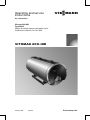
1
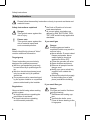
Operating and service
instructions
VIESMANN
for contractors
Vitomax 200-HW
Type M238
Oil/gas fired high pressure hot water boiler
Combustion output 4.0 to 18.2 MW
VITOMAX 200-HW
5592 548 GB
06/2007
Please keep safe.
Safety instructions
Safety instructions
Please follow these safety instructions closely to prevent accidents and
material losses.
Safety instructions explained
Danger
This symbol warns against the
risk of injury.
!
Please note
This symbol warns against the
risk of material losses and
environmental pollution.
Note
Details identified by the word "Note"
contain additional information.
Target group
These instructions are exclusively
designed for qualified personnel.
& Work on gas equipment must only
be carried out by a qualified gas fitter.
& Work on electrical equipment must
only be carried out by a qualified
electrician.
& The system must be commissioned
by the system installer or a qualified
person authorised by the installer.
&
the Code of Practice of relevant
trade associations,
& all current safety regulations as
defined by DIN, EN, DVGW, TRGI,
TRF, VDE and all locally applicable
standards.
If you smell gas
Danger
Escaping gas can lead to
explosions which may result in
serious injury.
& Never smoke. Prevent naked
flames and sparks. Never
switch lights or electrical
appliances ON or OFF.
& Close the gas shut-off valve.
& Open windows and doors.
& Remove all people from the
danger zone.
& Notify your gas or electricity
supplier from outside the
building.
& Shut off the electricity supply
to the building from a safe
place (outside the building).
If you smell flue gas
Observe the following when working
on this system
& all legal instructions regarding the
prevention of accidents,
& all legal instructions regarding
environmental protection,
2
Danger
Flue gas can lead to life-threatening poisoning.
& Shut down the heating system.
& Ventilate the boiler room.
& Close all doors leading to the
living space.
5592 548 GB
Regulations
Safety instructions
Safety instructions (cont.)
Working on the system
&
When using gas as fuel, also close
the main gas shut-off valve and
safeguard against unauthorised
reopening.
& Isolate the system from the power
supply and check that it is no longer
'live', e.g. by removing a separate
fuse or by means of a main isolator.
& Safeguard the system against
unauthorised reconnection.
Please note
Electronic modules can be
damaged by electro-static discharges.
Touch earthed objects, such as
heating or water pipes, to discharge static loads.
!
Please note
Repairing components which
fulfil a safety function can compromise the safe operation of
your heating system.
Replace faulty components
only with original Viessmann
spare parts.
Ancillary components, spare and
wearing parts
!
Please note
Spare and wearing parts which
have not been tested together
with the heating system can
compromise its function. Installing non-authorised components and non-approved
modifications/conversion can
compromise safety and may
invalidate our warranty.
For replacements, use only original spare parts from
Viessmann or those which are
approved by Viessmann.
5592 548 GB
!
Repair work
3
Index
Index
Operating information
Operating tips .............................................................................................
Operational checks .....................................................................................
Shutdown ...................................................................................................
Maintenance information.............................................................................
5
5
6
8
Commissioning, inspection, maintenance
Steps - commissioning, inspection and maintenance ...................................
Further details regarding the individual steps ..............................................
9
11
Additional information
Standard values for water quality ............................................................... 20
Commissioning/service reports ............................................................... 22
5592 548 GB
Keyword index .......................................................................................... 27
4
Operating information
Operating tips
According to the Pressure Equipment
Directive 97/23/EC, a steam boiler
category IV may only be taken into
use when the relevant authority has
granted permission for the installation
of the system, and an authorised
expert has tested the system.
The system must be commissioned by
the system installer or a qualified person authorised by the installer as well
the relevant expert.
Record all actual values in a commissioning/service report. These values
must be confirmed by the expert and
the system user.
According to the Pressure Equipment
Directive 97/23/EC, hot water boilers
category IV may only be operated,
supervised and maintained by a
trained boilerman.
The relevant authority may grant,
upon application, permission to operate the boiler without permanent
supervision, subject to it being
equipped in accordance with EN
12953 part 6.
In systems comprising several boilers, of which one is constantly used
as standby boiler, only change the
operation over in longer intervals, e.g.
during the annual inspection of the
total system.
We would recommend that you operate the boiler constantly at the
required operating pressure and temperature.
The continued boiler operation is still
advantageous, even if no heat is
drawn off for a longer period of time.
Operational checks
Danger
Boiler components that are not
thermally insulated can be subject to high temperatures that
can result in burns.
Take care with hot surfaces.
5592 548 GB
Subject to the safety equipment fitted
and the details in the permit certificate, either monitor the correct boiler
operation constantly, every 24 hours
or every 72 hours.
Determine the extent of checks
required in accordance with TRD 601,
sh. 1, section 7 [or local regulations].
Test the chemical composition of the
boiler water and feedwater constantly
in accordance with EN 12953 part 10
and VdTÜV datasheet 1466 [or local
regulations].
Carry out the following checks daily
or every 72 hours, subject to boiler
version and the manufacturer's specification (see also TRD 601, sh. 1):
& Blow down the boiler (only for boilers without automatic facility;
briefly open the valve two or three
times at operating pressure).
& Check the water level limiter.
& Check the feed and boiler water.
5
Operating information
Operational checks (cont.)
Carry out the following checks
monthly:
& Check the function of the safety
valve.
& Check the function of all control and
safety equipment.
& Check all connections and closures
for leaks.
& Check the installation room ventilation.
Have someone carry out the following
checks every six months (in accordance with TRD 602 and 604):
& Check the safety equipment.
& Check the burner.
& Check the thermal insulation on the
hot gas side, i.e. on lids and doors.
Record the results of the daily,
monthly and biannual checks in a log.
Shutdown
To prevent corrosion setting in during idle periods, when the boiler is not pressurised, conserve the boiler surfaces on the flue gas and water sides, subject to
the length of the period during which the boiler is taken out of use. There is a differentiation between wet conservation (during which exposure to oxygen is to
be avoided) and dry conservation (during which moisture levels are to be minimised).
Brief interruption of operation (1 to 2 days)
Water side
Recommendation: Maintain the boiler
pressure and temperature. Where that
is not possible and the boiler should
be depressurised for several days, we
would recommend the following:
To prevent oxygen corrosion, add an
oxygen binder with twice to three
times the standard dose to the feedwater from approx. one hour before
the boiler is shut down.
Flue gas side
5592 548 GB
Keep the heating surfaces dry.
Remove severe contamination as it
binds moisture.
6
Operating information
Shutdown (cont.)
Longer interruptions of operation
Water side
Wet conservation, as long as there is no risk of frost
1. Fill the boiler up to the highest possible level with treated feedwater.
To prevent oxygen corrosion, add
an oxygen binder to the boiler water
(e.g. sodium sulphite) in accordance with the manufacturer's
instructions. For this, ensure good
admixing with the boiler water
(thermal or mechanical agitation).
2. If, in multi-boiler systems, only
some boilers must be conserved,
these can be filled with desalinated
boiler water from the boilers that
remain in use, which will also maintain the temperature.
3. Maintaining pressure in a fully filled
boiler using nitrogen (preferably
nitrogen 5.0) of 0.1 to 0.2 bar can
prevent corrosion.
Dry conservation in case there is a risk of frost or in case of longer idle
periods
Drain the boiler at a temperature
between 120 and 140 °C, then open
the fittings on the water side.
Dry the boiler thoroughly and fill with
desiccant (e.g. silica gel) in accordance with the manufacturer's details.
Ensure that the desiccant does not
come into contact with the boiler
material. Then close the boiler again.
Check in regular intervals whether the
desiccant is still able to absorb moisture.
5592 548 GB
Flue gas side
Thoroughly clean and dry the surfaces on the flue gas side.
Maintain the alkaline balance of the
wash water (pH 8-9, in case of ammonia pH 10).
After the surfaces have been dried
completely, conserve them with a thin
film of graphite or boiled oil.
7
Operating information
Shutdown (cont.)
Keep the surfaces dry during the idle
periods (by inserting desiccant (e.g.
silica gel) or by air changes from a
connected dryer).
Further details
For further details, see the operating
instructions for conservation on the
water and hot gas side or the VdTÜV
datasheets (no. 1465, Oct. 1978) and
the VGB (no. R116H, 1981) [or local
regulations].
Maintenance information
Danger
Boiler components that are not
thermally insulated can be subject to high temperatures that
can cause burns.
Take care with hot surfaces.
5592 548 GB
The maintenance of a high pressure
hot water boiler is specified by the
TRD [or local] regulations.
8
Commissioning, inspection, maintenance
Steps - commissioning, inspection and maintenance
For further information regarding the individual steps, see the page indicated
!
•
Commissioning steps
!
•
•
5592 548 GB
Maintenance steps
Page
!
•
•
•
•
•
1. Starting the heating system . . . . . . . . . . . . . . . . . . . . . . . . . . . . . . . . . . . . . . . . . . . . . .
•
6. Extracting (if installed) and cleaning the
turbulators . . . . . . . . . . . . . . . . . . . . . . . . . . . . . . . . . . . . . . . . . . . . . . . . . . . . . . . . . . . . . . . . . . . . . . . . . . . . . . . 14
•
7. Cleaning the heating surface, the flue outlet and
flue pipe . . . . . . . . . . . . . . . . . . . . . . . . . . . . . . . . . . . . . . . . . . . . . . . . . . . . . . . . . . . . . . . . . . . . . . . . . . . . . . . . . . . . 15
•
•
8. Checking all seals/gaskets and packing cords on
the flue gas side
•
•
•
•
9. Checking the thermal insulation parts . . . . . . . . . . . . . . . . . . . . . . . . . . 15
•
•
11. Securing the clean-out cover and the combustion
chamber door . . . . . . . . . . . . . . . . . . . . . . . . . . . . . . . . . . . . . . . . . . . . . . . . . . . . . . . . . . . . . . . . . . . . . . . . . 16
•
•
12. Installing the burner . . . . . . . . . . . . . . . . . . . . . . . . . . . . . . . . . . . . . . . . . . . . . . . . . . . . . . . . . . . . . 17
•
•
14. Checking the inspection ports for leaks . . . . . . . . . . . . . . . . . . . . . . 17
•
•
16. Cleaning the sight glass in the combustion
chamber doors . . . . . . . . . . . . . . . . . . . . . . . . . . . . . . . . . . . . . . . . . . . . . . . . . . . . . . . . . . . . . . . . . . . . . . . 19
17. Checking the water quality . . . . . . . . . . . . . . . . . . . . . . . . . . . . . . . . . . . . . . . . . . . . . . . . 19
•
•
•
•
•
•
•
Inspection steps
11
2. Shutting down the system . . . . . . . . . . . . . . . . . . . . . . . . . . . . . . . . . . . . . . . . . . . . . . . . . 12
3. Removing the burner (if required) . . . . . . . . . . . . . . . . . . . . . . . . . . . . . . . . . . 13
4. Opening the cleaning door(s) . . . . . . . . . . . . . . . . . . . . . . . . . . . . . . . . . . . . . . . . . . . 13
5. Opening the clean-out cover and combustion
chamber door . . . . . . . . . . . . . . . . . . . . . . . . . . . . . . . . . . . . . . . . . . . . . . . . . . . . . . . . . . . . . . . . . . . . . . . . . 14
10. Inserting turbulators (if appropriate) and closing
the cleaning doors . . . . . . . . . . . . . . . . . . . . . . . . . . . . . . . . . . . . . . . . . . . . . . . . . . . . . . . . . . . . . . . . 16
13. Checking all connections on the water and steam
side for leaks
15. Check the function of all safety equipment in
accordance with the log for steam boiler systems
category IV. . . . . . . . . . . . . . . . . . . . . . . . . . . . . . . . . . . . . . . . . . . . . . . . . . . . . . . . . . . . . . . . . . . . . . . . . . . . . . . 18
18. Checking the installation room ventilation
9
Commissioning, inspection, maintenance
Steps - commissioning, inspection and . . . (cont.)
!
!
•
Inspection steps
Maintenance steps
Page
!
•
•
19. Checking the flue pipe for soundness
20. Adjusting the burner . . . . . . . . . . . . . . . . . . . . . . . . . . . . . . . . . . . . . . . . . . . . . . . . . . . . . . . . . . . . 19
5592 548 GB
•
Commissioning steps
10
Commissioning, inspection, maintenance
Further details regarding the individual steps
Starting the heating system
Details provided by the burner
manufacturer and regarding
accessories
1. Check that the turbulators (if
installed) are fully pushed into the
hot gas flues (open the cleaning
door(s)).
2. Check that the installation room
ventilation is open.
3. Check the function of the water
treatment system.
4. Fill the boiler with water and ventilate it.
Note
The water in hot water boilers
must comply with EN 12953 part
10; see also "Standard values for
water quality" on page 20.
5. Check all fitted components, such
as pipework, valves, regulators,
pumps etc. for function and leaks.
6. Check the system pressure.
7. Check the fuel oil level or the gas
supply pressure.
11. Switch ON the main isolator, the
switch for the boiler drives and
the burner control switch in this
order (observe the burner manufacturer’s operating instructions).
12. Start the boiler at a low output
(max. 30%) and gradually heat up
to a temperature of approx. 30 K
below operating temperature.
13. After the required flow temperature has been reached, gradually
open the boiler return valve and
possibly the feedwater valve as
well as the boiler flow valve.
14. Only then enable the full burner
load.
15. When heating the system from
cold (also when restarting after
maintenance and cleaning work),
prevent all heat transfer to consumers, to clear the dew point range
as quickly as possible.
16. After the operating temperature
has been reached, sequentially
switch on the heat consumers and
change over to automatic mode.
8. Open the flue gas damper (if
installed).
5592 548 GB
9. Check that the cleaning aperture
(s) on the flue outlet is/are closed.
10. Open the gas or oil supply line
shut-off valves.
11
Commissioning, inspection, maintenance
Further details regarding the individual steps (cont.)
17. Check the fittings for leaks prior to
and during the heat-up phase and
retighten, where required.
Retighten all fittings at max. permissible operating pressure. Torque values under cold and hot
conditions:
Closure
Hand hole
Head hole
Manhole
Dimensions
100 x 150,
M16
220 x 320,
M20
320 x 420,
M24
18. Check the boiler door(s) and
clean-out cover after approx. 50
hours for leaks and retighten all
screws.
Torque
100 Nm
200 Nm
350 Nm
Shutting down the system
1. Close the shut-off valves in the oil
lines (at the oil tank and filter) or
the gas shut-off valve.
2. Switch OFF the burner.
3. Isolate the system from the power
supply.
4. Close all valves.
5592 548 GB
Danger
Opening the boiler connections
and openings whilst the boiler
is under pressure can lead to a
high risk of severe injury.
Only open the connections on
the water and steam side and
inspection apertures after the
boiler has been completely depressurised.
12
Commissioning, inspection, maintenance
Further details regarding the individual steps (cont.)
Removing the burner (if required)
1. Remove the fuel supply line.
2. Undo screws A and remove burner with burner plate B.
Opening the cleaning door(s)
5592 548 GB
Undo screws A at cleaning door(s)
B and open the cleaning door(s).
13
Commissioning, inspection, maintenance
Further details regarding the individual steps (cont.)
Opening the clean-out cover and combustion chamber door
1. Remove clean-out cover B.
2. Open combustion chamber door
A.
Extracting (if installed) and cleaning the turbulators
5592 548 GB
Remove turbulators A without force.
For this, use the turbulator extractor
that is part of the cleaning equipment.
14
Commissioning, inspection, maintenance
Further details regarding the individual steps (cont.)
Cleaning the heating surface, the flue outlet and flue pipe
1. Clean flues A, combustion chamber B and reversing chamber with
the brush and remove combustion
residues.
2. Remove combustion residues from
the flue pipe and the flue outlet.
Checking the thermal insulation parts
1. Checking the thermal insulation
parts of combustion chamber door
A
5592 548 GB
2. Check the thermal insulation parts
on the clean-out doors, the combustion chamber entry, the cleanout cover and check inside the
reversing chamber.
15
Commissioning, inspection, maintenance
Further details regarding the individual steps (cont.)
Inserting turbulators (if appropriate) and closing the cleaning doors
1. Insert turbulators B (only in the
3rd flue C) as far as they will go.
2. Close the clean-out doors.
3. Tighten the screws on the cleanout doors A evenly and diagonally.
Securing the clean-out cover and the combustion chamber
door
1. Tighten down both clean-out covers B so they seal.
5592 548 GB
2. Close combustion chamber door
A and tighten it down so it seals.
16
Commissioning, inspection, maintenance
Further details regarding the individual steps (cont.)
Installing the burner
1. Secure burner plate B with
screws A to burner flange C.
2. For pressure-jet gas burner:
Fit the gas supply pipe.
Danger
Escaping gas leads to a risk
of explosion.
Test the soundness of all
gas connections.
Checking the inspection ports for leaks
Danger
Boiler components that are not
thermally insulated can be subject to high temperatures that
can result in burns.
Take care with hot surfaces.
Note
Replace the gaskets every time a connection has been opened.
Insert only gaskets approved in accordance with TRD 401, appendix 1,
VdTÜV [or local regulations].
5592 548 GB
Installation instructions of the
gasket manufacturer.
17
Commissioning, inspection, maintenance
Further details regarding the individual steps (cont.)
Check the function of all safety equipment in accordance
with the log for steam boiler systems category IV.
5592 548 GB
Check the safety valves plus the temperature and pressure limiters in
accordance with manufacturer's
details.
18
Commissioning, inspection, maintenance
Further details regarding the individual steps (cont.)
Cleaning the sight glass in the combustion chamber doors
Check the sight glass with gaskets A
for leaks and clean.
Checking the water quality
For standard values, see page 20.
Adjusting the burner
5592 548 GB
By the burner manufacturer or
authorised heating contractor.
19
Additional information
Standard values for water quality
According to the EN 12953 part 10
and the VdTÜV datasheet 1466
regarding the water quality for hot
water boilers in heating systems, the
following details apply to heating systems operated with flow temperatures
in excess of 100 °C:
Operation with circulating water with low salt content
Only use water with a low salt content
as fill or top-up water, such as desalinated water, permeate or condensate.
Systems using mixed condensate
generally create water with low salt
content if no boiler water is fed into
the system for putrefaction by alkalies.
Operation with saline water
Where possible, use water with a low
salt content that is at least free from
alkaline earths (softened) as fill or
top-up water.
with low salt content
μS/cm 10 to 30
> 30 to 100
General requirements
pH value at 25 ºC
pH value according to the
Drinking Water Order/
Drinking Water Treatment Order [or local regulations]
mg/
Oxygen (O 2)
(values for constant oplitre
eration are generally significantly lower)
*1 The
Clear, without sediments
9 - 10
≤ 9.5
Clear, without sediments
9 - 10.5
≤ 9.5
< 0.1
< 0.05
saline
> 100 to 1
500
Clear, without
sediments
9 - 10.5
≤ 9.5
< 0.02* 1
oxygen concentration in the re-circulated water may be up to 0.1 mg/litre, if suitable
inorganic corrosion inhibitors are used.
20
5592 548 GB
El. conductivity at 25 °C
Additional information
Standard values for water quality (cont.)
Alkaline earths (Ca + Mg) mmol/
litre
mg/
Phosphate (PO 4)
litre
Phosphate (PO 4) accord- mg/
ing to the Drinking Water litre
Order/Drinking Water
Treatment Order [or local
regulations]
mg/
Phosphate (PO 4) for
Viessmann hot water boi- litre
lers
When using oxygen binders:
Sodium sulphite
mg/
(Na 2SO 3)
litre
(When using other suitable products, observe the
respective guidelines issued by the relevant supplier.)
with low salt content
< 0.02
< 0.02
saline
< 0.02
<5
< 10
< 15
≤7
≤7
≤7
< 2.5
<5
< 15
–
–
< 10
&
Methyl ethyl ketoxime (Meko)
Tannic acid
These must be used with care, however, as they can give rise to oxidation, cleavage and transformation
products under boiler operating conditions. Please refer to the above guidelines for further information.
&
5592 548 GB
The VdTÜV datasheet 1466 advises
that further oxygen binders are
offered as chemicals that may have
the following active ingredients:
& Ascorbic acid
& Carbohydrazide
& Diethyl-hydroxylamine (DEHA)
& Hydroquinone
21
Commissioning/service reports
Commissioning/service reports
Commissioning
Service
Service
Service
Service
Service
Service
Service
Service
Service
Service
Service
Service
Service
Service
date:
by:
date:
by:
date:
by:
date:
by:
date:
5592 548 GB
by:
22
Commissioning/service reports
Vitomax 200-HW spare parts
Note
When ordering spare parts, please quote the serial number and the boiler type
(see type plate).
Tick the required spare parts and state the number required.
Obtain standard parts from your local supplier.
B Boiler type:
5592 548 GB
A Serial number:
23
Commissioning/service reports
Vitomax 200-HW spare parts (cont.)
B Boiler type:
5592 548 GB
A Serial number:
24
Commissioning/service reports
5592 548 GB
Vitomax 200-HW spare parts (cont.)
A Serial number:
B Boiler type:
25
Commissioning/service reports
Vitomax 200-HW spare parts (cont.)
B Boiler type:
5592 548 GB
A Serial number:
26
Keyword index
Keyword index
B
Burner installation . . . . . . . . . . . . . . . . . . . . . . . . 17
Burner, removal . . . . . . . . . . . . . . . . . . . . . . . . . . . 13
C
Cleaning door, opening . . . . . . . . . . . . . . . . 13
Clean-out cover, opening . . . . . . . . . . . . . . 14
Clean-out cover, securing . . . . . . . . . . . . . 16
Combustion chamber door, opening . .
. . . . . . . . . . . . . . . . . . . . . . . . . . . . . . . . . . . . . . . . . . . . . . .14
F
Fill and top-up water . . . . . . . . . . . . . . . . . . . . . 20
Flue outlet and flue pipe, cleaning . 15
Flue supply line . . . . . . . . . . . . . . . . . . . . . . . . . . . 13
S
Safety valve, checking . . . . . . . . . . . . . . . . . . . 6
Saline water . . . . . . . . . . . . . . . . . . . . . . . . . . . . . . . . 20
Shutdown . . . . . . . . . . . . . . . . . . . . . . . . . . . . . . . . . 6, 12
Sight glass, cleaning . . . . . . . . . . . . . . . . . . . . 19
Starting the heating system . . . . . . . . . . . 11
T
Thermal insulation parts, checking 15
Turbulators, extracting . . . . . . . . . . . . . . . . . 14
Turbulators, inserting . . . . . . . . . . . . . . . . . . . 16
W
Water quality . . . . . . . . . . . . . . . . . . . . . . . . . . . . . . . 20
Water with a low salt content . . . . . . . . . 20
5592 548 GB
M
Maintenance information . . . . . . . . . . . . . . . . 8
O
Operational checks . . . . . . . . . . . . . . . . . . . . . . . . 5
27
Subject to technical modifications.
chlorine-free bleached paper
Printed on environmentally friendly,
28
Viessmann Limited
Hortonwood 30, Telford
Shropshire, TF1 7YP, GB
Telephone: +44 1952 675000
Fax: +44 1952 675040
E-mail: [email protected]
5592 548 GB
Viessmann Werke GmbH&Co KG
D-35107 Allendorf
Telephone: +49 6452 70-0
Fax: +49 6452 70-2780
www.viessmann.com