Download User Manual - Vitomax 200
Transcript
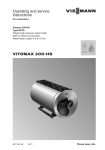
Operating and service
instructions
VIESMANN
for contractors
Vitomax 200-LW
Type M62A
Oil/gas low pressure hot water boilers
Rated output 2.3 to 6.0 MW
VITOMAX 200-LW
5592 607 GB
3/2009
Please keep safe.
Safety instructions
Safety instructions
Please follow these safety instructions closely to prevent accidents and material losses.
Safety instructions explained
Danger
This symbol warns against the
risk of injury.
!
Please note
This symbol warns against the
risk of material losses and environmental pollution.
Note
Details identified by the word "Note" contain additional information.
■ all current safety regulations as
defined by DIN, EN, DVGW, TRGI,
TRF, VDE and all locally applicable
standards,
■ Gas Safety (Installation & Use) Regulations
– the appropriate Building Regulation
either the Building regulations, the
Building Regulation (Scotland),
Building Regulations (Northern Ireland),
– the Water Fittings Regulation or
Water Bylaws in Scotland,
– the current I.E.E. Wiring Regulations.
Target group
If you smell gas
Regulations
Observe the following when working on
this system
■ all legal instructions regarding the prevention of accidents,
■ all legal instructions regarding environmental protection,
■ the Code of Practice of relevant trade
associations,
2
Danger
Escaping gas can lead to explosions which may result in serious
injury.
■ Never smoke. Prevent naked
flames and sparks. Never
switch lights or electrical appliances ON or OFF.
■ Close the gas shut-off valve.
■ Open windows and doors.
■ Remove all people from the
danger zone.
■ Notify your gas or electricity
supplier from outside the building.
■ Shut off the electricity supply to
the building from a safe place
(outside the building).
5592 607 GB
These instructions are exclusively
designed for qualified personnel.
■ Work on gas equipment must only be
carried out by a qualified gas fitter.
■ Work on electrical equipment must
only be carried out by a qualified electrician.
■ The system must be commissioned by
the system installer or a qualified person authorised by the installer.
Safety instructions
Safety instructions (cont.)
If you smell flue gas
Danger
Flue gas can lead to life-threatening poisoning.
■ Shut down the heating system.
■ Ventilate the boiler room.
■ Close all doors leading to the
living space.
Working on the system
■ When using gas as fuel, also close the
main gas shut-off valve and safeguard
against unauthorised reopening.
■ Isolate the system from the power supply and check that it is no longer 'live',
e.g. by removing a separate fuse or by
means of a main isolator.
■ Safeguard the system against unauthorised reconnection.
!
Ancillary components, spare and
wearing parts
!
Please note
Spare and wearing parts which
have not been tested together
with the heating system can compromise its function. Installing
non-authorised components and
non-approved modifications/conversion can compromise safety
and may invalidate our warranty.
For replacements, use only original spare parts from Viessmann
or those which are approved by
Viessmann.
Please note
Electronic modules can be damaged by electro-static discharges.
Touch earthed objects, such as
heating or water pipes, to discharge static loads.
Repair work
Please note
Repairing components which fulfil a safety function can compromise the safe operation of your
heating system.
Replace faulty components only
with original Viessmann spare
parts.
5592 607 GB
!
3
Index
Index
Operating instructions
Operating information
Notes on commissioning and operation...............................................................
Shutdown.............................................................................................................
Maintenance information......................................................................................
5
5
5
Service instructions
Commissioning, inspection, maintenance
Steps - commissioning, inspection and maintenance..........................................
Further details regarding the individual steps.......................................................
7
9
Standard values for water quality..................................................................... 21
Parts lists............................................................................................................ 26
Commissioning/service reports........................................................................ 28
5592 607 GB
Keyword index.................................................................................................... 29
4
Operating information
Notes on commissioning and operation
In systems comprising several boilers, of
which one is constantly used as a
standby boiler, only change the operation over after longer intervals, e.g. during the annual inspection of the total system.
Operating instructions on preserving the water and hot gas
sides
Operation
Only fill and operate boilers and heating
systems with water that complies with
the "Water quality guidelines" (see
page 21 onwards).
The system must be commissioned by
the system installer or a qualified relevant expert authorised by the installer.
Record all actual values in a commissioning/service report. These must be
confirmed by the installer, commissioning expert and the system user.
Within 4 weeks of the combustion equipment being commissioned, the operator
must notify the local flue gas inspector
accordingly [check local regulations].
We would recommend that you operate
the boiler constantly at the required operating pressure. Even if no heat demand
occurs for a longer period of time, it is still
better to operate the boiler continuously.
Shutdown
Control unit operating instructions
Operating instructions on preserving the water and hot gas
sides
5592 607 GB
Maintenance information
We recommend that your boiler system
is maintained regularly to ensure a faultfree, energy-conscious and environmentally responsible operation of your heating system.
The boiler must be cleaned at regular
intervals, otherwise the flue gas temperature can rise with increasing contamination resulting in higher energy losses.
We recommend the installation of a flue
gas thermometer. Monitoring the flue
gas temperature highlights incorrect
burner settings and the level of boiler
contamination.
5
Operating information
Maintenance information (cont.)
5592 607 GB
Excessive flue gas temperatures
through boiler contamination or incorrect
burner setting reduce the system efficiency. Where necessary, clean the
boiler or adjust the burner settings.
6
Commissioning, inspection, maintenance
Steps - commissioning, inspection and maintenance
For further information regarding the individual steps, see the page indicated
Commissioning steps
Inspection steps
Maintenance steps
•
•
•
•
•
•
•
•
•
•
•
•
•
•
•
•
•
•
•
•
•
•
•
•
•
•
•
•
•
•
12. Securing the cleaning cover.......................................... 16
•
•
•
21. Checking the water quality............................................ 19
•
•
•
•
•
•
•
•
•
•
•
•
•
5592 607 GB
•
•
•
•
1. Commissioning the heating system.............................
9
9. Cleaning the sight glass................................................ 13
2. Shutting down the system............................................. 10
3. Removing the burner (if required)................................. 11
4. Opening the boiler doors............................................... 11
5. Opening the cleaning cover........................................... 12
6. Removing and cleaning the turbulators (if fitted)........ 12
7. Cleaning the heating surfaces and flue gas collector. 13
8. Checking all seals/gaskets and packing cords on the
flue gas side
10. Checking thermal insulation parts and gaskets.......... 14
11. Inserting the turbulators (if fitted) and closing the
boiler doors..................................................................... 15
13. Installing the burner....................................................... 16
14. Checking all water connections for leaks
15. Checking the inspection ports for leaks...................... 17
16. Checking the water chamber for deposits................... 18
17. Checking the water level and system pressure
18. Checking the safety and control equipment
19. Checking the safety valve.............................................. 18
20. Checking all water connections for leaks after the
boiler has been filled...................................................... 18
22. Checking the thermal insulation
23. Checking the installation room ventilation
7
Service
•
Page
Commissioning, inspection, maintenance
Steps - commissioning, inspection and… (cont.)
Commissioning steps
Inspection steps
Maintenance steps
•
•
•
24. Checking the flue pipe for tightness
25. Adjusting the burner...................................................... 20
5592 607 GB
•
•
Page
8
Commissioning, inspection, maintenance
Further details regarding the individual steps
Commissioning the heating system
Details provided by the burner
manufacturer and regarding
accessories
01. Open the boiler doors and check
that the turbulators (if fitted) are fully
pushed into the hot gas flues.
10. Open the shut-off valves in the oil
lines (at the oil tank and filter) or
open the gas shut-off valve.
02. Check that the installation room
ventilation is unobstructed.
11. Switch ON the main isolator, the
ON/OFF switch for the boiler drives
and burner in this order.
!
Please note
Unsuitable water quality can
damage the boiler body.
Fill and operate the heating
system with water that complies with the "Water quality
guidelines" from page 21
onwards.
Note
Record the fill volume and total
hardness on page 19.
04. Check the system pressure.
05. Check all fitted components, such
as pipework, valves, regulators,
pumps etc. for function and leaks.
Burner manufacturer's operating instructions
12. Start the boiler at a low output (max.
30 %) and heat up to a temperature
of approx. 30 K below the operating
temperature.
The condensate drains must be
open and the condensate correctly
collected or drained.
13. After the required flow temperature
has been achieved, open the boiler
return valve and if required the feedwater valve and the boiler flow valve
- very slowly.
Service
03. Fill the heating system with water
and vent it.
5592 607 GB
09. Check that the dewatering line (if
installed) is correctly connected to
the condensate drain.
14. Only then enable the full burner
load.
06. Check the fuel supply for leaks and
pressure.
15. While the system heats up, check
the correct function of all control and
safety equipment.
07. Open the flue gas damper (if installed).
16. Observe the pressure and temperature test equipment.
08. Check that the cleaning aperture on
the flue outlet is closed.
9
Commissioning, inspection, maintenance
Further details regarding the individual steps (cont.)
17. Check the fittings for leaks and
tighten if required.
Closure Dimensions
Handhole 100 x 150,
M16
Torque
100 Nm
18. Check the boiler doors and cleaning
cover for leaks after approx. 50
hours run and retighten all screws
(torque approx. 5 to 10 Nm).
Shutting down the system
Danger
Heating water escaping under
pressure will injure bystanders.
Only open connections and
inspection ports on the heating
water side if the boiler has been
depressurised.
!
2. Close the shut-off valves in the oil
lines (at the oil tank and filter) or the
gas shut-off valve.
3. Isolate the system from the power
supply.
4. Close all valves.
Please note
Hot water can cause damage.
Never drain hot water into the
drainage system.
Ensure adequate cooling.
5592 607 GB
!
Please note
Draining the boiler with a suction
pump will create negative pressure inside the boiler.
Only drain the boiler with a suction pump if the air vent valve is
open.
1. Shut down the burner.
10
Commissioning, inspection, maintenance
Further details regarding the individual steps (cont.)
Removing the burner (if required)
1. Remove the fuel supply line.
2. Undo screws A and remove burner
with burner plate B.
Opening the boiler doors
5592 607 GB
Service
Undo screws A and swing open boiler
doors B.
11
Commissioning, inspection, maintenance
Further details regarding the individual steps (cont.)
Opening the cleaning cover
Undo nuts and remove cleaning covers
A and B.
Removing and cleaning the turbulators (if fitted)
5592 607 GB
Remove turbulators A without applying
force; to do so, use the turbulator extractor B supplied.
12
Commissioning, inspection, maintenance
Further details regarding the individual steps (cont.)
Cleaning the heating surfaces and flue gas collector
1. Clean flues A, combustion chamber
B and reversing chamber with suitable cleaning equipment and remove
combustion residues.
2. Remove combustion residues from
the flue gas collector (back).
Cleaning the sight glass
5592 607 GB
Service
Check the sight glass with gaskets A for
leaks and clean.
13
Commissioning, inspection, maintenance
Further details regarding the individual steps (cont.)
Checking thermal insulation parts and gaskets
5592 607 GB
Check thermal insulation parts A and
gaskets B.
Replace faulty parts.
14
Commissioning, inspection, maintenance
Further details regarding the individual steps (cont.)
1. Insert turbulators C (only in the 3rd
flue D) as far as they will go, using
the turbulator extractor A to do so.
2. Close boiler doors B.
5592 607 GB
3. Tighten boiler door screws evenly
(torque approx. 5 to 10 Nm).
15
Service
Inserting the turbulators (if fitted) and closing the boiler doors
Commissioning, inspection, maintenance
Further details regarding the individual steps (cont.)
Securing the cleaning cover
1. Secure both cleaning covers C so
they seal.
2. Position cleaning cover A over centering pin B and tighten evenly and
diagonally (torque approx. 10 Nm).
Installing the burner
1. Fit burner plate B with screws A to
burner flange C.
2. For pressure-jet gas burner:
Fit the gas supply pipe.
5592 607 GB
Danger
Escaping gas leads to a risk of
explosion.
Test the tightness of all gas
connections.
16
Commissioning, inspection, maintenance
Further details regarding the individual steps (cont.)
Checking the inspection ports for leaks
Danger
Boiler components that are not
thermally insulated can be subject to high temperatures that can
cause burns.
Take care with hot surfaces.
Installation instructions of the
gasket manufacturer.
Note
Replace the gaskets every time the connections and inspection ports are
opened.
Insert only gaskets approved in accordance with TRD 401, appendix 1, VdTÜV
[or local regulations].
HL
R
BÖ
Service
R
Caution - hot surface
R
Cleaning aperture
5592 607 GB
BÖ Inspection port
HL Handhole
17
Commissioning, inspection, maintenance
Further details regarding the individual steps (cont.)
Checking the water chamber for deposits
1. Fully drain the boiler.
!
Please note
Hot water can cause damage.
Never drain hot water into the
drainage system.
Ensure adequate cooling.
3. Clean sealing surfaces of the hand
hole cover and thread of the inspection port and replace the gaskets.
Seal the thread using hemp.
Retighten new gaskets after commissioning and check again after 24
hours run.
2. Clean the water chamber (hose it out)
and remove deposits via the drain. In
case of harder deposits that cannot
be removed by hosing down, carry
out chemical cleaning using an
approved descaling agent.
Checking the safety valve
Manufacturer's details
Checking all water connections for leaks after the boiler has
been filled
Replace the gaskets every time a connection has been opened.
3. Retighten all closures after commissioning.
5592 607 GB
1. Clean the sealing face.
2. Replace the gasket.
18
Commissioning, inspection, maintenance
Further details regarding the individual steps (cont.)
Checking the water quality
Enter the amount of top-up water and the total hardness of the boiler water into the
table.
For water quality guidelines, see from page 21 onwards
Fill
wate
r
m3
Top-up
water
m3
Meter
reading
m3
Total
water
volume
m3
Total hardness
pH
valu
e
Water treatment
Feed- Boile Boile Medi
water
r
r
um
wate wate
r
r
Date
Metering volume
—
5592 607 GB
Service
—
—
—
—
—
—
—
—
—
—
—
—
—
—
—
—
—
19
Commissioning, inspection, maintenance
Further details regarding the individual steps (cont.)
Adjusting the burner
Burner manufacturer’s details
Adjust to the maximum oil or gas
throughput of the burner to the rated
boiler output.
Rated output
MW
2.3
2.8
3.5
4.5
6.0
Hot gas pressure
drop
Pa
mbar
750
7.5
850
8.5
1000
10.0
1050
10.5
1400
14.0
To protect the system against dew point
corrosion, the full load must be set to the
rated boiler output and must not be
switched off during the summer months
(full load at constant standby).
5592 607 GB
The minimum boiler water temperature
is 70 ºC. Adjust the return temperature
raising facility to a minimum temperature
of 50 ºC (operation with oil) or to 55 °C
(operation with gas).
20
Standard values for water quality
Standard values for water quality
The service life of any boiler as well as that of the complete heating system is influenced by the quality of the water.
The cost of a water treatment facility is certainly less than the cost of repairing damage
to the boiler system.
Maintaining the following requirements is necessary to safeguard your warranty
rights. The manufacturer's warranty excludes damage due to corrosion and scaling.
The following is a summary of essential water qualities.
A chemical water treatment can be ordered from Viessmann for filling.
Heating systems with rated operating temperatures up to 100 ºC
(VDI 2035)
Prevent excessive scale build-up (calcium carbonate) on the heating surfaces.
For heating systems with operating temperatures up to 100 °C, the VDI Directive
2035 Sheet 1 "Prevention of heating system damage – scaling in DHW and hot
water heating systems" applies [in Germany] together with the following standard values (see also the full explanations
in the original Directive):
Total alkaline earths mol/m3
< 0.02
Soften the fill & top-up water in heating
systems operating under the following
conditions:
■ The total of alkaline earths in the fill &
top-up water exceeds the standard
value.
■ Higher fill & top-up water volumes are
expected.
5592 607 GB
The standard values assume the following:
■ The volume of fill and top-up water of
the heating system during its service
life will not exceed three times the
water content of the heating system.
■ The specific system volume is less
than 20 l/kW output. In multi-boiler systems, apply the output of the smallest
boiler.
■ All measures to prevent corrosion on
the water side in accordance with VDI
2035 Sheet 2 have been implemented.
Total hardness in °dH
< 0.11
21
Service
Total output in kW
> 600
Standard values for water quality
Standard values for water quality (cont.)
When engineering the system, observe
the following:
■ Install shut-off valves in different sections. This prevents the need for draining the entire heating water in case of
repairs or system expansion.
■ Install a water meter to record the
amount of the fill & top-up water. Enter
the volume of water filled and the
water hardness into the boiler service
instructions.
5592 607 GB
Operating information:
■ Bring the system into use step by step,
starting with the lowest boiler output
and a high heating water flow rate.
This prevents a localised concentration of lime deposits on the boiler heating surfaces.
■ During expansion or repair work, only
drain the necessary sections.
■ Where water treatment is required,
treat even the first fill of the heating
systems prior to commissioning. This
also applies to any subsequent filling,
e.g. when adding top-up water or after
a repair or after system expansion.
■ Filters, dirt traps and other blow-down
or separating facilities in the heating
water circuit must be checked,
cleaned and activated more frequently
after commissioning or recommissioning, and later on as required, subject
to the water treatment applied (e.g.
water softening).
The build-up of lime deposits on the
heating surfaces will be minimised if
these instructions are observed.
Any lime deposits that have formed
because the requirements to VDI Guideline 2035 were not observed will in most
cases already have caused a reduction
in the service life of the boilers installed.
Removing the lime deposits is one option
to restore the operational viability. This
measure must be carried out by the
Viessmann industrial services or a specialist company. Inspect the heating system for possible damage prior to returning it into use. It is essential that the faulty
operating parameters are corrected to
prevent renewed formation of excessive
scale deposits.
22
Standard values for water quality
Standard values for water quality (cont.)
Heating systems with permissible flow temperatures in excess
of 100 ºC (VdTÜV MB 1466)
Operation with circulating water with
low salt content
Only use water with a low salt content as
fill or top-up water, such as desalinated
water, permeate or condensate.
Systems using mixed condensate generally create water with low salt content
if no boiler water is fed into the system
for putrefaction by alkalis.
Operation with saline water
Where possible, use water with a low salt
content that is at least free from alkaline
earths (softened) as fill or top-up water.
El. conductivity at 25 °C
10 to 30
> 30 to 100
clear, without sediments
9 - 10
≤ 9.5
clear, without sediments
9 - 10.5
≤ 9.5
With salt
content
> 100 to
1500
clear, without sediments
9 - 10.5
≤ 9.5
mg/litre
< 0.1
< 0.05
< 0.02*1
mmol/litre
mg/litre
mg/litre
< 0.02
<5
≤7
< 0.02
< 10
≤7
< 0.02
< 15
≤7
mg/litre
< 2.5
<5
< 15
μS/cm
General requirements
5592 607 GB
pH value at 25 ºC
According to the potable
water order/potable water
treatment order
Oxygen (O2)
(values for constant operation are generally significantly
lower)
Alkaline earths (Ca + Mg)
Phosphate (PO4)
According to the potable
water order/potable water
treatment order
For Viessmann hot water
boilers
*1
Service
Low salt content
The oxygen concentration in the re-circulated water may be up to 0.1mg/litre, if
suitable inorganic corrosion inhibitors are used.
23
Standard values for water quality
Standard values for water quality (cont.)
When using oxygen binders:
Sodium sulphite (Na2SO3)
mg/litre
(When using other suitable
products, observe the
respective guidelines issued
by the supplier)
Low salt content
With salt
content
–
< 10
–
Prevention of damage through corrosion on the water side
The corrosion resistance of materials
used on the heating water side of heating
systems and boilers depends on the
absence of oxygen in the heating
water.
The oxygen introduced into the heating
system with the first fill and the top-up
water reacts with the system materials
without causing damage.
The characteristic blackening of the
water after some time in use indicates
that free oxygen is no longer present.
The technical rules and in particular VDI
Directive 2035-2 therefore recommend
that heating systems are designed and
operated so that a constant ingress of
oxygen into the heating water is prevented.
5592 607 GB
Opportunities for oxygen ingress during
the operation:
■ Through overflowing open expansion
vessels
■ Through negative pressure in the system
■ Through gas-permeable components
Sealed systems – e.g. systems with a
diaphragm expansion vessel – offer
good protection against the ingress of
airborne oxygen into the system if they
are correctly sized and operate at the
correct pressure.
At every part of the heating system, even
at the suction side of the pump and under
all operating conditions, the system
pressure should be above ambient
atmospheric pressure.
The pre-charge pressure of the diaphragm expansion vessel should be
checked at least during the annual service. Also see chapter "General design
information" for information regarding
pressure maintenance systems and corrosion.
The use of permeable components, e.g.
plastic pipes that are permeable to gas
in underfloor heating systems, should be
avoided. Provide system separation if
such components are nevertheless
used. This must separate the water flowing through the plastic pipes from other
heating circuits, e.g. from the boiler, by
the provision of a corrosion resistant
heat exchanger.
24
Standard values for water quality
Standard values for water quality (cont.)
5592 607 GB
Service
No further anti-corrosion measures are
required for sealed hot water heating
systems subject to the above points
being observed.
However, take additional precautions
where there is a risk of oxygen ingress,
for example by adding oxygen binder
sodium sulphite (5 - 10 mg/litre into the
excess). The heating water should have
a pH value between 8.2 and 9.5.
Different conditions apply to systems
that contain aluminium components.
Where chemicals are used as part of the
corrosion protection, we recommend
that the manufacturer of the chemicals
issues a certificate of suitability of the
additives with regard to the boiler materials and the materials of the other heating equipment components.
We recommend you refer questions of
water treatment to an appropriate specialist.
Further details can be found in VDI
Directive 2035-2 and EN 14868.
25
Parts lists
Parts lists
When ordering spare parts:
Please enter the serial number and type,
as well as the number of articles
required.
Type M62A
Pos.
Component
1
Profiled gasket per boiler
door
Pack per boiler door
Insulation mat per boiler
door
Insulation ring
Burner connection pack
Cleaning cover pack
Rear boiler floor pack
Pack per cleaning aperture
Hand hole gasket
100 x 150
Seal ring set
2*2
3*2
4
5*2
6*2
7*2
8*2
9
10
Obtain standard parts from your local
supplier.
0_1
Quantity
0_2
Quantity
Boiler size
0_3
0_4
QuanQuantity
tity
0_5
Quantity
*2
A corresponding amount of installation adhesive is provided.
26
5592 607 GB
Please order individual parts from:
Viessmann-Industrie-Service
Tel.: 0049-30/6602 389
Email: [email protected]
Internet: www.viessmann-industriekessel.de
Parts lists
5592 607 GB
Service
Parts lists (cont.)
27
Commissioning/service reports
Commissioning/service reports
Commissioning
Service
Service
Service
Service
Service
Service
Service
Service
Service
Service
Service
Service
Service
Service
date:
by:
date:
by:
date:
by:
date:
by:
date:
5592 607 GB
by:
28
Keyword index
Keyword index
A
Adjusting the burner...........................20
Anti-corrosion measures....................25
I
Inserting the turbulators.....................15
Installing the burner...........................16
B
Burner, removal.................................11
M
Maintenance information......................5
C
Checking gaskets...............................14
Checking the inspection ports............17
Checking thermal insulation parts......14
Checking the safety valve..................18
Checking the water chamber.............18
Checking water connections..............18
Chemicals for corrosion protection....25
Cleaning the flue gas collector...........13
Cleaning the heating surfaces...........13
Cleaning the sight glass.....................13
Cleaning the turbulators.....................12
Closing the boiler doors.....................15
Commissioning....................................5
Commissioning the heating system.....9
Corrosion...........................................24
Corrosion on the water side...............24
O
Opening the boiler doors....................11
Opening the cleaning cover...............12
D
Diaphragm expansion vessel.............24
E
Expansion vessel...............................24
S
Saline water.......................................23
Securing the cleaning cover...............16
Shutdown.............................................5
Shutting down the system..................10
T
Total alkaline earths.............................9
Total boiler water hardness..................9
Total hardness of the boiler water......19
V
Venting the heating system..................9
W
Water quality......................................19
Water quality, standard values...........21
Water treatment.................................25
Water with a low salt content.............23
5592 607 GB
F
Fill and top-up water..........................19
Filling the heating system with water...9
Flow temperature...............................23
29
30
5592 607 GB
31
5592 607 GB
Subject to technical modifications.
chlorine-free bleached paper
Printed on environmentally friendly,
32
Viessmann Limited
Hortonwood 30, Telford
Shropshire, TF1 7YP, GB
Telephone: +44 1952 675000
Fax: +44 1952 675040
E-mail: [email protected]
5592 607 GB
Viessmann Werke GmbH&Co KG
D-35107 Allendorf
Telephone: +49 6452 70-0
Fax: +49 6452 70-2780
www.viessmann.com


