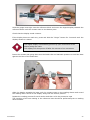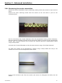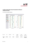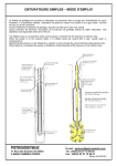
1
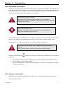
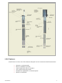
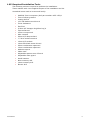
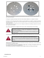
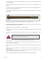
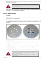
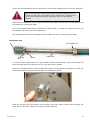
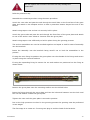
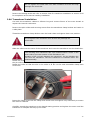
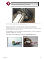
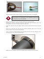
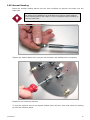
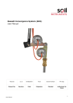
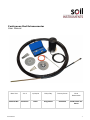
Continuous Rod Extensometer User Manual Man 224 2.0.2 11/08/14 Philip Day Jeremy Scott Chris Rasmussen Manual No. Revision Date Originator Checked Authorised for Issue User Manual 1 Contents Section 1 : 1.01 1.02 1.03 1.04 1.05 Section 2 : 2.01 2.02 2.03 2.04 2.05 Section 3 : 3.01 3.02 Section 4 : 4.01 4.02 4.03 4.04 Section 5 : 5.01 User Manual Introduction .................................................................................................. 3 Important information ...................................................................................... 3 System components ......................................................................................... 3 Familiarisation ................................................................................................. 4 Features.......................................................................................................... 5 Required Installation Tools ................................................................................ 6 Installation.................................................................................................... 7 Borehole Preparation ........................................................................................ 7 Down Hole Installation ...................................................................................... 7 Up Hole Installation ........................................................................................ 11 Transducer Installation ................................................................................... 15 Manual Reading ............................................................................................. 19 Advanced installation .................................................................................. 21 Shortening the anchor assemblies .................................................................... 21 Installing Hydraulic anchors in cased boreholes .................................................. 22 Maintenance ................................................................................................ 24 Taking care of your Continuous Rod Extensometer digital readout ........................ Battery Changing ........................................................................................... Calibration .................................................................................................... Trouble shooting ............................................................................................ 24 24 24 24 Help and Support......................................................................................... 25 FAQ .............................................................................................................. 25 2 Section 1 : Introduction 1.01 Important information Thank you for choosing the Soil Instruments Continuous Rod Extensometer. This manual has been written to help you install the Continuous Rod Extensometer. Please read this manual thoroughly before use and keep it handy when installing the Continuous Rod Extensometer. The following symbols are used throughout the manual: This Symbol indicates a warning. Failure to observe the warning may result in injury, product malfunction, unexpected readings or damage to the product that may invalidate its warranty. This symbol indicates a tip. Additional information that may be helpful when installing the Continuous Rod Extensometer system Soil Instruments has an ongoing policy of design review and reserves the right to amend the design of the Continuous Rod Extensometer and this instruction manual without notice. Please refer to our terms and conditions of sale for warranty information. Only use the correct battery type as supplied fitted to the digital readout. Using incorrect battery types may damage the digital display. Products marked with the countries. symbol are subject to the following disposal rules in European This product is designated for separate collection at an appropriate collection point Do not dispose of as household waste For more information, contact Soil Instruments Ltd or the local authorities in charge of waste management 1.02 System components Depending upon system configuration you should have the following system components: Manual reading system: User Manual 3 Manual reading Continuous Rod Extensometer anchor and head tube assemblies Reference head plate Head plate fixing kit ( Expanding or resin fixing ) Grout plate Digital readout for manual reading anchors Grout pipe Air vent pipe Installation tool kit Remote reading system: Remote reading Continuous Rod Extensometer anchor and head tube assemblies Reference head plate and cover assembly Head plate fixing kit ( Expanding or resin fixing ) Grout plate Displacement transducers ( Vibrating Wire or potentiometer ) Grout pipe Air vent pipe Installation tool kit Multicore cable 1.03 Familiarisation The Continuous Rod Extensometer unit comprises an anchor unit either groutable or hydraulic to which a length of coated fibreglass rod is attached. The other end of the fibreglass is attached to a reading point within the head tube. A polyethylene tube covers the fibreglass rod and connects to both the anchor and the head tube. The rod assemblies are assembled in the factory to specified lengths as either manual reading or remote reading assemblies and set for a specific transducer range. Up to 8 rod assemblies can be connected to either a manual reading or remote reading head and are suitable for either up hole or down hole installations. User Manual 4 1.04 Features Listed below is a short list of the features designed into the Continuous Rod Extensometer. User Manual Minimal on site assembly Ease of installation process Light weight and easy to transport Up to eight measuring points Suitable for installation in confined spaces Speed of installation 5 1.05 Required Installation Tools The following tools are required to perform the installation. Those marked with # are supplied as part of the installation tool kit. Unmarked items need to be sourced locally. User Manual Modified 7mm nut spinner (Soil part number 1055-152)# Tube of silicon grease# Cutting knife# 1/8” flat blade screw driver# Junior hacksaw# Flat file# 2.5mm A/F hexagon key(Allen key)# Tape measure# 10mm nut spinner# Side cutters# 22mm A/F deep socket# ½” drive socket wrench# 13mm A/F socket# 12mm flat blade screw driver# 22mm combination spanner# 13mm combination spanner# Adhesive tape # Cable ties# Adjustable spanner max 27mm# Adjustable mole grips# Small hammer 8mm masonry drill 14mm masonry drill Electric drill 6 Section 2 : Installation This section will describe the basic sequence of operations required to install the Continuous Rod Extensometer. 2.01 Borehole Preparation The Continuous Rod Extensometer is designed for boreholes of 100mm and above. The borehole should be free of debris and drilled 600mm deeper than the longest specified anchor position. If the borehole has been drilled short or the anchors need to be shortened then see the advanced installation section in this manual. Anchor locations should be predetermined prior to ordering of the anchor assemblies. The locations are often dictated by the geology and geometry of the ground to be monitored. One anchor usually the deepest should be located in stable ground to serve as a reference point for the rest of the anchors in the head The reference head should be recessed into the borehole if it is likely to be damaged by blasting or other construction activity. Alternatively a protective enclosure can be used in exposed locations. For down hole installations manhole covers can be used to protect the head assemblies. For down hole installations ensure the recesses and manholes have suitable drain holes to prevent water filling the recess or manhole. 2.02 Down Hole Installation Identify the correct head plate and the correct anchor assembly lengths for the borehole to be installed. The head plate and grout plate both have the holes for the head tubes marked with letters from “A” through to “H” as required. Use the M14 nuts and bolts on the grout plate to blank off the holes on the grout plate which are not fitted to the head plate so that the open holes in the grout plate match those in the head plate. User Manual 7 Position the grout plate centrally over the borehole and mark the plate fixing positions onto the mounting surface. If using the expanding fixing kit drill the holes at 8mm diameter to a depth of 120mm. If using the resin fixing kit drill the holes at 14mm diameter to a depth of 160mm and bond the fixings into the holes with only the threaded section of the fixing protruding above the mounting surface. Check that the grout plate fits over the fixings and allow the bonding compound to set for the required time period. The anchor assemblies are supplied coiled up for ease of transportation and handling. Attached to each anchor assembly is a packet containing the components required to attach the displacement transducers or perform manual readings. Ensure this packet is removed and retained for later assembly to the installed anchor. Uncoil the rod assemblies onto an area which is as flat as possible and close to the borehole. Care should be taken when releasing the ties that restrain the coil. Cut the ties one at a time starting at the anchor end, releasing one coil at a time ensuring that the remaining coils do not release violently. When all the assemblies for the chosen borehole have been uncoiled they can be allocated to hole positions in the grout plate. It is recommended that they be allocated by depth with “A” being the deepest anchor and hole position “B” being the next deepest etc. The allocations should be recorded and stored safely for later use during monitoring. Protective Cap User Manual 8 Anti Rotation Nut Securing Nut O Ring Head Tube To fit the anchor head tube to the grout plate remove the protective cap and securing nut from the head tube and lubricate the “O” ring with silicon grease. Insert the threaded section of the head tube through the assigned hole position so that the thread protrudes through to the side with the stamped positions. Refit the securing nut and tighten into position using the 22mm socket while holding the head tube by the anti rotation nut with the 22mm spanner Do not tighten with excessive force as this may damage the head tube. Refit the protective cap. Assemble the remaining anchors using the same procedure. Uncoil the grout tube and pass the end through the front face of the grout plate and attach to the end of the deepest anchor. Attach using tape or ties sufficiently to hold in place whilst inserting the system into the borehole but not so tight that it can not be broken free during the grouting process. User Manual 9 The anchor assemblies can now be bundled together and taped or tied for ease of assembly into the borehole. Lower the assembly into the borehole being careful not to kink the assemblies in the process. If using the resin fixing kit position the grout plate over the threads of the fixings and secure in place using the nuts and washers. If using the expanding fixing kit ensure the nut and washer are positioned on the fixing as shown below. Position the grout plate onto the mounting surface over the drilled holes. Insert the fixings through the grout plate and into the holes and hammer into the hole until the nut and washer contact the grout plate. Tighten the nuts until the grout plate is secured in position. Connect the grout tube to the grout pump and pump sufficient water through the grout tube to lubricate it. Mix up the grout using Portland cement and water at a ratio of approximately 1:1 by volume. Do not use any sand in the grout mixture. Pump the grout into the borehole whilst slowly withdrawing the grout pipe. After completion of the borehole grouting, flush water through the grout tube so that it can be reused on the next borehole. After the grout has set fully, remove the protective caps and securing nuts from the head tubes. Remove the nuts and washers from the fixings and remove the grout plate from the mounting surface. Place the reference head plate over the head tube threads and onto the fixing studs ensuring that it is in the same orientation as the grout plate. Loosely refit the head tube securing nuts followed by the fixing nuts and washers. User Manual 10 Tighten all the nuts to finger tight and then tighten them all progressively until the head plate is secured in position. Do not tighten the head tube nuts with excessive force as this may damage the head tube. Remove the setting studs and refer to section 2.04 for transducer installation or section 2.05 for completion of the manual reading installation. 2.03 Up Hole Installation Identify the correct head plate and the correct anchor assembly lengths for the borehole to be installed. The head plate and grout plate both have the holes for the head tubes marked with letters from “A” through to “H” as required. Use the M14 nuts and bolts on the grout plate to blank off the holes on the grout plate which are not fitted to the head plate so that the open holes in the grout plate match those in the head plate. Position the grout plate centrally over the borehole and mark the plate fixing positions onto the mounting surface. If using the expanding fixing kit drill the holes at 8mm diameter to a depth of 120mm. If using the resin fixing kit drill the holes at 14mm diameter to a depth of 160mm and bond the fixings into the holes with only the threaded section of the fixing protruding above the mounting surface. Check that the grout plate fits over the fixings and allow the bonding compound to set for the required time period. The anchor assemblies are supplied coiled up for ease of transportation and handling. Attached to each anchor assembly is a packet containing the components required to attach the displacement transducers or perform manual readings. Ensure this packet is removed and retained for later assembly to the installed anchor. User Manual 11 Uncoil the rod assemblies onto an area which is as flat as possible and close to the borehole. Care should be taken when releasing the ties that restrain the coil. Cut the ties one at a time starting at the anchor end, releasing one coil at a time ensuring that the remaining coils do not release violently. When all the assemblies for the chosen borehole have been uncoiled they can be allocated to hole positions in the grout plate. It is recommended that they be allocated by depth with “A” being the deepest anchor and hole position “B” being the next deepest etc. The allocations should be recorded and stored safely for later use during monitoring. Protective Cap Anti Rotation Nut Securing Nut O Ring Head Tube To fit the anchor head tube to the grout plate remove the protective cap and securing nut from the head tube and lubricate the “O” ring with silicon grease. Insert the threaded section of the head tube through the assigned hole position so that the thread protrudes through to the side with the stamped positions. Refit the securing nut and tighten into position using the 22mm socket while holding the head tube by the anti rotation nut with the 22mm spanner User Manual 12 Do not tighten with excessive force as this may damage the head tube. Refit the protective cap. Assemble the remaining anchors using the same procedure. Uncoil the vent tube and pass the end through the small hole on the front face of the grout plate and attach to the deepest anchor so that it protrudes 300mm beyond the end of the anchor. Attach using tape or ties so that it is securely held in place. Uncoil the grout tube and pass the end through the front face of the grout plate and attach to one of the anchor outer tubes at 2 metres from the grout plate. Attach using tape or ties sufficiently to hold in place during the grouting process. The anchor assemblies can now be bundled together and taped or tied for ease of assembly into the borehole. Insert the assembly into the borehole being careful not to kink the assemblies in the process. If using the resin fixing kit position the grout plate over the threads of the fixings and secure in place using the nuts and washers. If using the expanding fixing kit ensure the nut and washer are positioned on the fixing as shown below. Position the grout plate onto the mounting surface over the drilled holes. Insert the fixings through the grout plate and into the holes and hammer into the hole until the nut and washer contact the grout plate. Tighten the nuts until the grout plate is secured in position. Due to the high pressures involved in the grouting process the grouting must be performed in two stages. The first stage is to create a 1.5 metre grout plug to seal the head of the borehole. User Manual 13 Use the shortest length of grout tube possible and connect the grout tube to the grout pump then pump sufficient water through the grout tube to lubricate it. Mix up the required amount of grout using Portland cement and water at a ratio of approximately 1:1 by volume. Do not use any sand in the grout mixture. Pump the required amount of grout into the borehole to create a 1.5 metre plug. After completion of the borehole grouting, flush sufficient water through the grout tube so that it can be reused on the next stage of grouting. Allow the grout to set for a minimum of 24 hours. After the first stage grouting has set reconnect the grout pump and continue to grout the borehole until grout exits the vent tube. Do not use excessive grout pressures as this may blow out the grout plug. In fractured ground there may be leakage into the fractures causing the top anchor to become un-grouted. Grouting may need to be continued at intervals until the point at which grout is seen to flow from the vent tube immediately upon recommencing of grouting, at which point the grout column is probably complete and covering the top anchor. Seal off the grout and allow the grout to set. After the grout has set fully, remove the protective caps and securing nuts from the head tubes. Remove the nuts and washers from the fixings and remove the grout plate from the mounting surface. Cut the grout and vent tubes flush with the grout surface. Ensure that the grout and vent tubes do not protrude above the surface of the grout. Place the reference head plate over the head tube threads and onto the fixing studs ensuring that it is in the same orientation as the grout plate. Loosely refit the head tube securing nuts followed by the fixing nuts and washers. Tighten all the nuts to finger tight and then tighten them all progressively until the head plate is secured in position. User Manual 14 Do not tighten the head tube nuts with excessive force as this may damage the head tube. Remove the setting studs and refer to section 2.04 for transducer installation or section 2.05 for completion of the manual reading installation. 2.04 Transducer Installation Cut back the transducer cables to 250mm long and remove 50mm of the outer sheath to expose the internal conductors. Remove the split collets and securing screws from the transducer clamp bushes and retain in a safe place. Thread the transducer clamp bushes onto the head tubes and tighten down into position. Do not tighten with excessive force as this may damage the head tubes. Slide the collet onto the stem of the transducer and insert the transducer into the head tube. The vibrating wire transducer has a pin located within a notch in the stem tube to prevent rotation of the transducer rod. Rotation of the rod with damage the transducer, do not withdraw the rod from the transducer until the transducer is installed within the head assembly. Rotate the transducer in a clock wise direction whilst maintaining forward pressure to keep the pin within the notch until the transducer is fully tightened into the rod connector. Rotate the collet so that the slot in the collet is at 90° to the most accessible clamp bush screw hole. Insert the clamp screw into the clamp bush screw hole and tighten only sufficiently to ensure the collet is retained. Carefully extend the transducer to its desired staring position and tighten the screw until the transducer is clamped securely by the collet. User Manual 15 The transducer start position can be established by reading the transducer and referring to the calibration certificate or by measuring from the top of the clamp bush to the body of the transducer and extending the transducer to the required position. Install the remaining transducers and record the initial reading from each transducer, noting the serial number of the transducer and the hole position. Thread 1 metre of the multicore cable through the cable gland in the head cover. Strip back 600mm of the outer sheaf of the cable to expose the internal conductors. Using the gel filled crimp connectors supplied connect each transducer to the multicore cable ensuring that the wiring code is recorded. Set the mole grips so that the crimp button is depressed when the grips are closed but the grips do not crush the body of the crimp. Insert the two wires to be joined fully into the crimp and then depress the button. User Manual 16 Test all connections after crimping to ensure continuity and security of connections. If using vibrating wire transducers it is only necessary to connect the thermistor from one of the transducers to monitor temperature of all the transducers in the head assembly. Feed all the connections into the void at the centre of the transducer array. Withdraw the multicore cable back through the cable gland until the stripped end of the outer sheath is level with the internal wall of the head cover. Tighten the cable gland fully then apply a smear of silicon grease to the “O”ring on the head plate. Position the head cover over the head and transducer assembly taking care to feed the surplus conductor wires into the head assembly. Check no wires are trapped between the head plate and the cover then rotate the cover anticlockwise by 120° until the threads engage. Rotate the cover clockwise until the cover tightens down securely on the “O”ring seal. User Manual 17 Cut the multicore cable to the desired length and re-test the connections. User Manual 18 2.05 Manual Reading Insert the manual reading datum into the 7mm modified nut spinner and insert into the head tube. For down hole installations a small amount of silicon grease applied to the reading datum will retain it in the nut spinner while inserting it into the head tube. Tighten the reading datum fully into the rod connector and withdraw the nut spinner. Repeat for the remaining anchors. To read the anchors remove the digital readout from the carry case and insert the reading tip into the reference block. User Manual 19 Hold the gauge boss tight into the reference block and move the digital display towards the reference block until the contact rests on the datum point. Check that the display reads 0.00mm. If the display does not read zero, press and hold the “Origin” button for 3 seconds until the display resets to 0.00mm The digital display automatically powers up upon movement of the display along the track. The display will auto power off after 20 minutes of no movement. Insert the contact and gauge boss into the head tube and maintain pressure to hold the boss against the face of the head tube. Slide the display towards the boss until the contact rests on the reading datum and record the reading that is show on the display along with the anchor position. Repeat the reading process for each anchor and then re-fit the protective caps The checking of the zero setting in the reference boss should be performed prior to reading each borehole. User Manual 20 Section 3 : Advanced installation 3.01 Shortening the anchor assemblies Should the anchor assemblies require shortening setting studs and protective caps must be fitted. Remove the three retaining screws from the anchor at the end where it joins to the connecting tube. Pull the connecting tube (20mm diameter) from the polyethylene tubing (16mm diameter), this may require a number of people as the connecting tubing is a tight fit onto polyethylene tubing. After removal measure and cut back the required amount of polyethylene tubing using a sharp blade. Cut back the of coated fibreglass rod by the same amount using a fine blade hacksaw. Cut back the coating on the fibreglass by 100mm using a sharp blade and using a file chamfer the corner of the fibreglass as shown below. Remove the connector tube from the anchor and ensure the fibreglass fits easily into the anchor. User Manual 21 Hold the anchor onto the fibreglass so that the fibreglass is fully inserted into the hole. Measure 360mm from the face of the anchor back up the polyethylene tubing and mark the position on the tubing using tape. Remove the anchor from the fibreglass and re-fit the connecting tube to the anchor then apply silicon grease to the polyethylene tubing. To refit the connecting tube and anchor to the polyethylene tubing, a bucket of very hot water and a hard surface such a concrete is required. Place the end of the connecting tube into the hot water so that 200mm of it is submerged in the hot water. After 2-3 minuets remove the anchor and connecting tube assembly from the hot water and immediately push onto the fibreglass and polyethylene tubing up until the mark on the polyethylene tubing. If the connecting tube grabs onto the polyethylene tubing immediately start tapping hard the end of the anchor onto the concrete surface while holding the polyethylene tubing. This hammer effect will break the friction between the tubes allowing the connector tube to be positioned in line with the tape mark. Ensure that the fibreglass is visible through all the rod securing holes in the anchor and then replace the rod securing screws and tighten very tightly to secure the fibreglass in place. 3.02 Installing Hydraulic anchors in cased boreholes Where the ground is too weak for a borehole to remain open without being cased the anchor assemblies must be fitted to a special head plate that is able to pass through the casing. Hydraulic anchors are typically supplied with hydraulic tubing that is cut and fitted to the anchors on site as required. A hand-operated hydraulic pump is normally used to activate the anchors. Connect the hydraulic tubing from the anchor to the hydraulic pump using the couplings and olives provided. Fill the pump reservoir with oil then loosen the join at the tube to anchor connector and start pumping. Bleed the air from the tube at the tube to anchor connector until all the air within the tubing is replaced by oil and then re-tighten the coupling. When all the anchors are primed with oil install them onto the head plate and the anchor assemblies can now be bundled together and taped or tied along with the hydraulic tubing for ease of assembly into the borehole. The head plate and rod assemblies should be suspended from nylon rope to the drill tower and lowered into their final position ensuring that the head plate is at its correct level. As the first section of casing is withdrawn it is recommended that the deepest anchor should be activated first once clear of the casing. Operant the pump to extend the anchor prongs, pressure will build before the prongs in the anchor begin to extend and then will drop once the prongs start to activate. The level of oil in the hydraulic reservoir will drop as the prongs continue to extend. User Manual 22 Pressure will build as the prongs push into the soil, the prongs are fully extended when the pressure increases rapidly and the correct volume of oil has been displaced. Single acting anchors will have an oil displacement of approximately 100ml; double acting sensors will have twice this volume. When the anchor has been installed, disconnect the tubing from the pump and seal it off. As each section of casing is withdrawn the nylon rope is untied from the drill mast and withdrawn from the casing section and then re-secured to the drill tower. The casing is withdrawn until the next anchor is clear of the casing and then this anchor is activated. The procedure is repeated for all the other anchors. When the casing has been completely removed from the borehole the special head plate can be replaced with the grout plate and the borehole grouted as required. User Manual 23 Section 4 : Maintenance 4.01 Taking care of your Continuous Rod Extensometer digital readout Soil Instruments Continuous Rod Extensometer digital readout has been designed for use in harsh environments however certain precautions should be observed to ensure a long reliable product life. Do not drop The Continuous Rod Extensometer digital readout may malfunction if subjected to strong shocks or vibrations. Do not immerse or expose to water jets The Continuous Rod Extensometer digital readout has been designed to be used in a dry environment and may malfunction if immersed under water or used in a wet environment. Keep away from strong magnetic fields Do not use or store this device in the vicinity of equipment that generates strong electro-magnetic radiation or magnetic fields. Avoid extremes of temperature Do not expose to extreme heat or cold temperatures as this may cause damage to the Continuous Rod Extensometer digital readout. . 4.02 Battery Changing The low battery indicator will show when the battery needs replacing. If the Continuous Rod Extensometer digital readout is not to be used for a long period of time then it is recommended that the battery should be removed before storage. 4.03 Calibration Soil Instruments recommends that the Continuous Rod Extensometer digital readout is returned for inspection, cleaning and Calibration every 12 months. 4.04 Trouble shooting 1. The digital display will not turn on. Replace the battery. 2. After replacing the battery the digital display will still not turn on. Contact technical support at www.soilsupport.co.uk 3. The readings are unstable or intermittent. Clean the sliding scale of the digital display. User Manual 24 Section 5 : Help and Support 5.01 FAQ How do I know which sweep range I should be using? The sweep range is determined by the frequency range of the type of instrument you are reading. This information is normally supplied in the instrument user manual or data sheet e.g. if the instrument has a specified frequency range of 1700 to 3000 Hz then select sweep range D as this is the smallest range that encompasses the instruments specified range. If you do not know what type or what the specified frequency range is then set the sweep range to range A and if the resultant reading is stable i.e. not changing by more than 1-2 digits, you can then set the sweep range to the one which best covers this reading e.g. if the reading is 7000 F²/1000 then select sweep range D as this is the narrowest range that 7000 F²/1000 fits into. Make a note of the setting so that next time the instrument is read the correct range can be selected. Why are different types of frequency units used? The measurement of vibrating wire instruments is the frequency of oscillation of the wire. This is measured by the recorder as the number of oscillations per second or hertz (Hz) This unit of measurement is not linear in relation to the change in strain of the wire, so the Hz reading is often linearized by squaring and dividing by 1000 to give the unit F²/1000 also called linear or digits. Another unit for measuring the frequency is Period, this is the length of time taken for one oscillation to occur and is measured in seconds. Typically for vibrating wire instruments this value is very small, so it is multiplied by 10 7 to give a four digit number. Hz and Period require more complex formulae in order to convert the frequency readings into engineering units. Soil Instruments recommends using the F²/1000 units displayed and stored by the Vibrating wire data recorder. Bell Lane, Uckfield, East Sussex t: +44 (0) 1825 765044 e: [email protected] TN22 1QL United Kingdom f: +44 (0) 1825 744398 w: www.itmsoil.com Soil Instruments Ltd. Registered in England. Number: 07960087. Registered Office: 5th Floor, 24 Old Bond Street, London, W1S 4AW User Manual 25