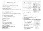
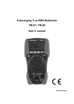
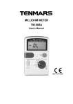
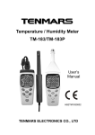
1
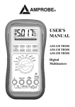
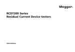
3-Phase / Rotation Motor Tester TM-601N / 603 / 604 User’s Manual HB2TM601N000 CONTENTS 1. Preface......................................................... 2 2. Application ................................................... 2 3. Features:...................................................... 3 4. Panel display................................................ 3 5. How to operate............................................. 4 5.1 How to test the 3 phases of AC .................... 4 5.2 How to test the motor’s direction of rotation . 5 6. Easy test ...................................................... 9 7. Electrical specifications ...............................11 8. Accessories included: .................................11 9. Safety precautions and procedures ........... 12 10. The following symbols are used: ................ 14 11. Safety and maintenance standards............ 15 12. Battery Replacement.................................. 16 13. Service ....................................................... 19 14. End of life ................................................... 20 TM-601N/603/604 1. Preface Thank you for buying our excellent product. Products available on the market are not very user-friendly: their test AC phase and motor phase are separated from each other, have two sockets (to be plugged out before use), etc. When you use the you will not have these troubles anymore, and time is saved. So enjoy it ! 2. Application Test for poles of the 3-phase power source, L1/A, L2/B and L3/C, and identify which phase for which wire. Determine the 3-phase motor’s direction of rotation (clockwise or counterclockwise) and the circuit status of the motor wires. EN-2 TM-601N/603/604 3. Features: In each test, Push “ ” button turn on the meter, push “ ”button again to turn off the meter. or auto shut off after 15 minutes ( TM-601N) Check the 3 wires of the power cord, L1, L2 and L3 through the 3 red lamps, which indicate if each wire is connected well. Check if L1, L2 and L3 are in place, the 3 motor wires, the motor’s direction of rotation, and the ER red/green OK indicators. When the battery is low, an indicator will turn ON to remind you to replace it. hold the power button and check the panel indicator. (TM-603/604) Two UL 500mA/700V fuse .(TM-601N) Waterproof resist IP67.(TM-601N) 4. Panel display 3 red lamps(L1, L2 and L3) ER red/green OK indicators. Low battery indicator (see step 10) EN-3 TM-601N/603/604 5. How to operate 5.1. How to test the 3 phases of AC Let your crocodile clip clamp the 3-phase power terminal. In each test, hold the power button and check the indicators on the panel. If L1, L2 and L3 are lit, it means normal. (In this case, skip to step 2.) If one of them remains unlit, L1 for example, it means the wire for L1 is disconnected or in power failure mode. You may check visually or with a multimeter if the wire is connected well. Next, check if the red or green lamp is lit. If it is the green lamp, it suggests L1, L2 and L3 are correct for their phases. (In this case, skip to step 6). If it is the ER red lamp, it means L1, L2 and L3 are wired incorrectly. You must correct them before proceeding to step 3. Exchange L2 and L3. If the green lamp goes ON, it means the 3 phases are correct. (In this case, skip to step 6.) If the red lamp ER goes ON, it means the 3 phases are wired incorrectly. You must EN-4 TM-601N/603/604 correct them before going to the next step. Exchange L1 and L3. If the green lamp goes ON, it means the 3 phases are correct. (In this case, skip to step 6.) If the red lamp ER goes ON, it means the 3 phases are wired incorrectly. You must correct them before going to the next step. Exchange L1 and L2. If the green lamp goes ON, it means the 3 phases are correct. (In this case, skip to step 6.) Note the definition for L1, L2 and L3 each. 5.2. How to test the motor’s direction of rotation Make sure the motor’s power source has been removed. Connect the test wire to the motor terminal. In each test, press the power button, then check the indicators on the panel: when the motor is not turning, the red lamp is ON. The green lamp goes ON when the motor EN-5 TM-601N/603/604 turns clockwise, and the red lamp goes ON when it turns counterclockwise. (Normal; skip to step 8.) If the motor turns clockwise and counterclockwise and the red lamp remains ON (the red and green lamps do not go ON alternately), this suggests one wire is disconnected or not connected well. Please measure the motor’s 3 wires with a multimeter and check if there is a disconnection between any 2 wires. (If the motor is disconnected, change it.) The green lamp goes ON when the motor turns clockwise, and the red lamp turns ON when it turns counterclockwise. This suggests the wiring of L1, L2 and L3 is normal. (In this case, skip to step 8.) If the red lamp goes ON when the motor turns clockwise, and the green lamp goes ON when it turns counterclockwise, this indicates that the wiring sequence must be corrected. Go to step 5. Exchange L2 and L3. The green lamp goes ON when the motor turns clockwise, EN-6 TM-601N/603/604 and the red lamp goes ON when it turns counterclockwise, this suggests the wiring of L1, L2 and L3 is normal. (In this case, skip to step 8.) If the red lamp goes ON when the motor turns clockwise, and the green lamp goes ON when it turns counterclockwise, this indicates the wiring sequence must be corrected. Go to step 6. Exchange L1 and L3. If the green lamp goes ON when the motor turns clockwise, and the red lamp goes ON when it turns counterclockwise, skip to step 8. If the red lamp goes ON when the motor turns clockwise, and the green lamp goes ON when it turns counterclockwise, this indicates the wiring sequence must be corrected. Go to step 7. Exchange L1 and L2. If the green lamp goes ON when the motor turns clockwise, and the red lamp goes ON when it turns counterclockwise, this suggests the wiring of L1, L2 and L3 is normal. (In this case, skip to step 8.) EN-7 TM-601N/603/604 Once the green lamp goes ON when the motor turns clockwise, and the red lamp goes ON when it turns counterclockwise, the 3 phases are correct. Then the motor’s R.S.T. can be connected to the power system’s L1, L2 and L3. Now your motor can run correctly. EN-8 TM-601N/603/604 6. Easy test 6.1.1. Motor turning test 6.1.2. Wiring and lamps EN-9 TM-601N/603/604 Off On Phase indication phase rotation not defined L1 Rotate right Power on Rotate left L1 missing L2 missing L3 missing EN-10 L2 L3 TM-601N/603/604 7. 8. Electrical specifications Battery life : about 50 hours Operating Temperature : 5℃~40℃,80%RH Storage temp. & RH : -10℃~60℃,70%RH. Overvoltage category : CAT IV 600V, CAT III 1000V. Dimensions (with holster) : 143×68×35 mm. Weight (including battery) : about 150g. Inter phase voltage : 45V AC up to 600 AC. Signal Frequency Range : 45 to 400 Hz. Test Currents (In per phase) less than : 3.5 mA Motor POWER:6W ~160W Accessories included: User manual. 9V battery(NEDA 1604 IEC 6F 22 JIS 006P)*1carrying case. Test leads should be 4 feet long*3. CE120cm ( 4 feet ). Test leads should be removable and have alligator clips*3. EN-11 TM-601N/603/604 9. Safety precautions and procedures This instrument conforms with safety Standard EN 61010-1 related to electronic measuring instruments. For your own safety and to avoid damaging the instrument follow the procedures described in this instruction manual and read carefully all notes preceded by this symbol . CAUTION For your own safety and to avoid damaging the instrument follow the procedures described in this instruction manual and read carefully all notes preceded by this symbol . When taking measurements: Avoid doing that in humid or wet places. Avoid doing that in rooms where explosive gas, combustible gas, steam or excessive dust is present. EN-12 TM-601N/603/604 Keep you insulated from the object under test. Do not touch exposed metal parts such as test lead ends, sockets, fixing objects, circuits etc. Avoid doing that if you notice anomalous conditions such as breakages, deformations, fractures, leakages of battery liquid, blind display etc. Be particularly careful when measuring voltages exceeding 20V to avoid risks of electrical shocks. EN-13 TM-601N/603/604 10. The following symbols are used: °C AUTION - refer to the instruction manual - an improper use may damage the instrument or its components Danger high voltage: risk of electric shock Double insulated meter AC voltage or current DC voltage or current Earth EN-14 TM-601N/603/604 11. Safety and maintenance standards The instrument complies with : UL61010-1,and CSA C22.2 No.61010-1 (between ground and input terminal) and EN 61010-1(2001) and EN61557. Operating altitude : below 2,000m. Operating environment: for indoor use, expose to pollution level II. This is a precision device. During use or storage, do not go beyond its spec. to prevent any possible damage or danger. Do not put this device in direct sunlight or where it is hot and/or damp. Remember to turn OFF the power after use. For long storage, remove the battery to prevent the battery from leaking to cause damage to the parts inside. Clean the device with a dry soft cloth. Wet cloths, liquid and water are prohibited. EN-15 TM-601N/603/604 12. Battery Replacement Battery Replacement When the symbol Low battery LED is displayed, batteries need replacement. CAUTION Before replacing batteries disconnect the test leads from any energized circuits to avoid electrical shocks. Turn OFF the meter and disconnect the test leads from the input terminals. Unscrew the battery cover and remove the battery. Insert a new battery of the same type (9V NEDA1604, JIS006P, IEC6F22) observing the proper polarity, re-screw the battery cover and reposition the protective holster. EN-16 TM-601N/603/604 Conditions This instrument is guaranteed for one year against material or production defects, in accordance with our general sales conditions. During the warranty period the manufacturer reserves the right to decide either to repair or replace the product. Should you need for any reason to return back the instrument for repair or replacement take prior agreements with the local distributor from whom you bought it. Do not forget to enclose a report describing the reasons for returning (detected fault). Use only original packaging. Any damage occurred in transit due to non original packaging will be charged anyhow to the customer. The warranty doesn’t apply to: Accessories and batteries (not covered by warranty). Repairs made necessary by improper use (including adaptation to particular applications not foreseen in the instructions manual) or improper EN-17 TM-601N/603/604 combination with incompatible accessories or equipment. Repairs made necessary by improper shipping material causing damages in transit. Repairs made necessary by previous attempts for repair carried out by non skilled or unauthorized personnel. Instruments for whatever reason modified by the customer himself without explicit authorization of our Technical Dept. The contents of this manual may not be reproduced in any form whatsoever without the manufacturer’s authorization. Our products are patented and our logotypes registered. We reserve the right to modify specifications and prices in view of technological improvements or developments which might be necessary. EN-18 TM-601N/603/604 13. Service Shouldn’t the instrument work properly, before contacting your distributor make sure that batteries are correctly installed and working, check the test leads and replace them if necessary. Should you need for any reason to return back the instrument for repair or replacement take prior agreements with the local distributor from whom you bought it. Do not forget to enclose a report describing the reasons for returning (detected fault). Use only original packaging. Any damage occurred in transit due to non original packaging will be charged anyhow to the customer. The manufacturer will not be responsible for any damage to persons or things. EN-19 TM-601N/603/604 14. End of life Caution : this symbol indicates that equipment and its accessories shall be subject to a separate collection and correct disposal. EN-20 Professional Electrical and Environment Test & Measurement Instruments: Battery Capacity / Impedance Tester, TACHO Meter ,LED light meter, Temperature & Humidity meter ,Infrared Thermometer, Sound level meter ,Light meter, EMF meter, UV Light meter, RF meter, Hot wire Anemometer, CO meter Anemometer, Lan cable tester, CO2 meter, Solar power meter, Radiation meter, Clamp meter, Multimeter, Phase Rotation test, Digital Insulation tester Our products of high quality are selling well all over the world TENMARS ELECTRONICS CO., LTD 6F, 586, RUI GUANG ROAD, NEIHU, TAIPEI 114, TAIWAN. E-mail: [email protected] http://www.tenmars.com