1
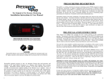
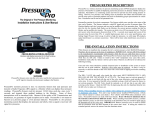
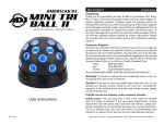
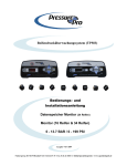
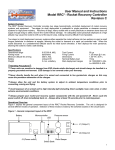
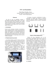
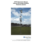
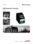
PRESSUREPRO DESCRIPTION
Installation Instructions & User Manual
PressurePro is a wireless electronic tire pressure monitoring system (TPMS) designed to display
tire pressures. PressurePro is capable of displaying current tire pressures on demand, whether
moving or stationary. PressurePro is a monitoring system and will not prevent tires from losing
pressure or failing. However, low pressure is the leading cause of premature tire failure and
PressurePro can provide early notice of potential problems and assist in maintaining proper
pressurization in vehicle tires. PressurePro can be used on all pneumatic tires.
PRESSUREPRO 16 WHEEL MONITOR
PressurePro consists of two basic components: Tire Sensors which screw onto the valve stems of
the tires, and a Monitor. The Sensors transmit a coded RF signal and can alert if pressure drops.
The Monitor displays each tire’s pressure and can send an audible alert if tire pressures drop.
During an alert, the low tire location light flashes on the Monitor, the current pressure reading
for that tire flashes, and an audible alert sounds. The system can alert at two (2) low pressure
levels: The first alert occurs when tire pressures drop more than 12.5%. A second, more
urgent alert occurs if tire pressures drop by more than 25%. A variable high pressure alert, set
to your specifications, (see Setting Upper Pressure Alert on pg. 6) alerts to high tire pressures.
As with many RF products, signal interference is a common occurrence. There will be times
when interference can prevent a reading.
The Original in Tire Pressure Monitoring
Monitors and displays pressures for 10 wheel locations
on the Primary vehicle and 6 on the tow.
PRE-INSTALLATION INSTRUCTIONS
When Sensors are installed, they recognize the tire’s current pressure as their BASELINE pressure.
Therefore, the tire pressure at the time of installation is IMPORTANT! All tires MUST be inflated to
the manufacturer's recommended cold pressures while the tires are cold (best time is in the morning
before vehicle movement). The PressurePro tire Sensors must then be installed on the tires while they
are still cold. Failure to install at this "cold" temperature may cause false alerts. Installations made
after the vehicle is driven can be done if Sensors are allowed to re-reference the following morning.
PRESSUREPRO 34 WHEEL MONITOR
Monitors and displays pressures for 10 wheel locations
on the Primary vehicle and 24 on the tow.
SENSORS
PressurePro Sensors screw onto the valve stem, read the tire’s pressures and use
an RF signal to transmit current pressure readings to the Monitor.
PressurePro monitors pressure in tires via electronic Sensors that read pressures and transmit a
Radio Frequency (RF) signal to a Monitor which can display those pressure readings.
PressurePro Sensors read tire pressure 12,343 times each day (once each 7 seconds) and transmit
these updated readings to the Monitor. Some of these transmissions will be interfered with.
Because of the quirks of RF Transmissions and interference, no guarantee of signal reception can
be made. PressurePro is not meant to function as a pressure gauge or a low pressure indicator.
PressurePro is a tire pressure monitoring system that displays tire pressures and which, when a
signal is received, will signal low pressures.
1
Tires and valve stems should be carefully inspected prior to installation of the system to ensure that
they are in good condition. Defective valve stems must be replaced. At times, it may be necessary
to clean the threads of the valve stem with a wire brush or tapping tool before installing a sensor.
The DILL VALVE (the small valve inside the valve stem) MUST DEPRESS FULLY AND
RELEASE AIR FOR THE SENSOR TO ACTIVATE. The Sensor may not activate properly if the
Dill Valve pin is not flush with the end of the valve stem allowing a good interface to the valve
stem. It is not unusual to find dill valves installed too deep, which will cause the Sensor to not
activate properly. The Dill Valve should be centered so it will not slip to one side when screwing
on the Sensor. Check the Dill Valve by depressing the end of a thumbnail directly into the dill
valve to make sure it releases air.
NOTE: When installing Sensors on vehicles with existing tire pressure monitoring
sensors or aluminum valve stems: PressurePro uses a brass thread and brass and
aluminum can chemically bond with exposure to salts and chemicals. When installing
PressurePro Sensors on these aluminum stems, do the following: 1) put a drop of oil on
the threads of the stem; 2) put Teflon tape on the stem; 3) remove sensors at least once
(1) per month to help prevent bonding. PressurePro is not responsible for damage to
aluminum stems.
If using valve stem extensions, it is important to tighten extensions securely to valve stem. Always
check the Dill Valves in extensions for proper air release. After installing Sensors, check for
leaks by coating the Sensor, extension and valve stem with a solution of 1 part liquid soap to 2
parts water – look for bubbles which indicate a leak.
2
INSTALLATION INSTRUCTIONS
1.
2.
DO NOT INSTALL SENSORS ON TIRES! First – attach power cord to Monitor and
plug the power cord into the cigarette lighter socket (or use optional hard-wired
connections). When power is on, the green light below the “ON” button flashes once every
5 seconds. Position the Monitor temporarily at the desired mounting location (so it can be
moved for best signal reception). (If using the Optional Coaxed Antenna Kit or Echo
Repeater, position the antenna/repeater temporarily at the desired mounting location.)
PLACE THE SYSTEM INTO “PROGRAM MODE” by pressing and holding the
“SET” button for 5 seconds. Release “SET” when the small green power light shifts
from flashing and become a continuous green light. The front driver’s side tire location
light on the Monitor display will begin to flash. The words "NO SEN SOR" will scroll
across the digital display on a new installation. You are now in Program Mode. (Note:
The system exits "Program Mode" if there is no activity for 10 minutes. If this happens,
you can resume programming from stopping point by getting back in program mode and
using your Up or Down arrows to get to your next location.)
3.
SCREW A SENSOR ONTO THE VALVE STEM of the tire at the location denoted
by the flashing location light. Tighten firmly by hand (or with the optional PressurePro
sensor installation tool). Using any tools, (other than PressurePro tool) can damage the
Sensor and voids the Warranty. IMPORTANT - Listen for the “release” of air when
screwing on the Sensor. (It is not unusual for the dill valve to be seated too deeply in the
valve stem. Check dill level by testing with thumb nail – placing nail straight onto the
plunger to ensure it opens and a burst of air is released.)
4.
WAIT FOR THE MONITOR TO DISPLAY A PRESSURE READING. This can take
up to 60 seconds and is the only time a pressure reading will be displayed while the
Monitor is in “Program Mode”. This initial pressure reading from the Sensor is your
BASELINE pressure.
5.
ONCE A PRESSURE READING IS DISPLAYED, LOCK IN SENSOR, by pressing
and holding the “SET” button until the flashing tire location light on the Monitor moves to
the next tire location (normally about two seconds). This locks that Sensor’s code to that
wheel position in the Monitor and must be done to retain that sensor’s ID. If you do not
want to install a Sensor to the next wheel location, use the “UP” or “DOWN” arrow
buttons to move the flashing light to the location desired and install (repeat from step 3
forward).
6.
7.
3
After installing the last Sensor, and it displays a pressure reading, YOU MUST AGAIN
PRESS THE “SET” BUTTON UNTIL THE RED FLASHING LOCATION LIGHT
MOVES TO THE NEXT TIRE LOCATION. It is OK if this is a tire location that already
has a Sensor installed - it will simply display 3 dashes (---). To go out of “Program
Mode” and into “Normal Mode” press the “ON” button. The system is now installed and
operating.
Complete a permanent installation of the Monitor with provided Velcro or purchased
mounting accessories. If using the Optional Antenna Kit, complete the permanent
installation of the antenna.
MONITOR – FEATURES
•
Normal Mode – Monitor is in Normal Mode when first powered up. Monitor is
listening for Sensor updates and alerts in Normal Mode. Green light below “ON”
button flashes every 5 seconds when in Normal Mode. Tire pressures can be
displayed by selecting a tire with “UP” or “DOWN” arrow.
•
Program Mode – Used for programming Sensors to the Monitor. (See
“Installation Instructions” step #2) When in Program Mode, green light is solid,
tire location selected is flashing and display shows 3 dashes (“- - -“) for locations
programmed previously. Non-programmed locations will flash when selected and
will display “No Sen Sor” message. When a new Sensor is installed, a pressure
value will display on Monitor.
Monitor Front,
Back, or both
vehicles. 1 button,
3 pushes.
Activates lights - takes
system out of
Program Mode,
Scroll tires
Clockwise
Scroll tires
counterclockwise
“SET” program mode,
confirm setting,
delete Sensor(s)
Sensor Low
Battery Indicator
IMPORTANT: Products using RF signals are subject to interference of the signal causing a
loss of signal. Reception depends on the environment and conditions present at the time of
use. PressurePro has been designed to be as reliable as possible with the use of RF
transmissions. There is no guarantee of signal reception. This device complies with part 15
of the FCC rules. Operation is subject to the following two conditions: (1) This device may
not cause harmful interference, and (2) this device must accept any interference received,
including interference that may cause undesired operation.
4
MONITOR BUTTON FUNCTIONS
SENSOR ALERTS
"ON" Button
• When in Normal Mode – Pushing and/or holding “ON” button will light up all
tire locations that have been programmed.
• When in Program Mode -- Pushing “ON” button exits Program Mode.
• FIRST STAGE LOW PRESSURE ALERT - (alerts at 12.5% pressure loss from
initial pressure at installation). A first stage alert level will “beep,” and flash tire
location, and display low pressure - once per second – until the low pressure is
corrected or the “ON” button is pressed putting Monitor in “reminder mode” or
Monitor is unplugged. Pull over, inspect tire and repair. If no button is pressed to
mute system – system will continue to alert.
•
SECOND STAGE LOW PRESSURE ALERT - (alerts at 25% pressure loss initial
pressure at installation). A second stage alert level will “beep”, flash tire location and
pressure value twice per second. If no button is pressed to mute system – system will
alert until low pressure is corrected or for a total of 15 hours. Pull over and repair.
•
REMINDER MODE – To “mute” the audible alert, place into “reminder” mode by
pressing the “ON” button briefly. Audible alert will sound periodically.
•
Deleting a Single Sensor/Location: With a tire location selected, holding “SET”
button for approx. 10 seconds (while in “Normal Mode”), will delete that tire location
from the active list. Note: After approx. 5 seconds, green light will remain on;
continue to hold “SET” until the green light and the selected tire location turn off
(approx. 10 seconds). Display will show “Del”. Deletion of Sensor is complete.
“SIGNAL CHECK IN” FEATURE – A Patent Pending feature of the PressurePro
system is the “check-in” feature. Sensors send short millisecond “check-in” signal
bursts regularly. As with all RF devices, a signal may be lost or interrupted. If a signal
is lost or interrupted, the Monitor will light that wheel location with a solid light –
(there is no alert beep). If this type alert continues, it may indicate a Sensor has been
removed, lost or damaged or a signal is not being received - check that Sensor’s
location.
•
Deleting all Sensors/Locations at one time: All installed Sensors can be deleted
simultaneously by holding the “SET” button for 45 seconds. (When holding SET
button, the following will happen: After 5 seconds, the green light will go solid; hold
for another 10 seconds and “DEL” appears on Monitor face; continuing to hold for 30
seconds deletes all readings and Monitor to display “No Sen Sor”.)
MULITIPLE LOW PRESSURE ALERTS – In the unlikely event that multiple
alerts occur, the Monitor will flash all low locations with low pressures. When
selected, a tire location with an alert will flash its pressure and position while the alert
sounds. (Non-selected low pressure tires will flash their wheel location every 2
seconds.)
•
High Pressure Alerts (Variable) – Alerts at determined percentage over initial
pressure at installation. The level of the alert can be set by end user to OFF or at 10%,
15%, 19%, 24%, 28%, 33%, 40% and 45% over the set level. Note: Sensors come from
the factory set to trigger at 24% high.
“F/B” Button – (when separating a vehicle from a tow)
When separating the main vehicle from the tow, push F/B button. All tires with
Sensors will light and display on the Monitor. Press F/B button until just the vehicle
you want to use is active (lit on the Monitor display). System will monitor that
vehicle only. Use the F/B button to reattach both vehicles. Press F/B button until
vehicles you want active are lit. (Press F/B button until all programmed lights are lit
putting system in monitoring mode for both vehicle and tow.)
“SET” Button
Entering Program Mode from Normal Mode: Hold “SET” button (approx 5
seconds) until the green light below the “ON” button remains on.
“UP” & “DOWN” Buttons
In Both Normal and Program Mode – Push “UP” arrow to rotate selected tire
location clockwise. Push “DOWN” arrow to rotate selected tire location
counterclockwise.
5
SETTING UPPER PRESSURE ALERT
1. Unplug the power cord from the Monitor (mini-USB connector).
2. While holding down the UP Arrow button, plug the power cord back into the
Monitor and it will advance to the next alert level higher (new alert level will
display on the screen).
3. Release the UP button.
4. If the Monitor displays the upper alert pressure you desire, setting the upper alert is
completed. If it is not the upper alert you desire, repeat steps #1 and #2 until you
see the desired alert level.
5. The high alert function can be turned OFF by repeating steps #1 and #2 after the
45% level is reached.
6. To turn the high alert function back ON, repeat steps #1 and #2 going to the 10%
alert level which will display.
6
HOW TO GUIDE
FREQUENTLY ASKED QUESTIONS
CHECKING TIRE PRESSURES – Sensors send an updated pressure reading
approx. every 5 minutes. Pressing the “UP” or “DOWN” button, (Monitor in Normal
Mode), will select a tire location to display. To reset baseline pressure, remove
Sensor for 60 seconds, then reinstall. REMOVING AND REPLACING A SENSOR
ON THE VALVE STEM IMMEDIATELY AFTER DRIVING CAN RESULT IN
“FALSE” ALERTS. ALLOW TIRES TO COOL TO AMBIENT TEMPERATURE.
CAN I STORE MY VEHICLE WITH THE MONITOR ON? The Monitor draws 25mA to
150mA of power. It’s possible the Monitor could drain the vehicle's battery over an extended
period of time. If storing for more than 1 month, it’s advised to unplug Monitor and remove
Sensors (see “Tips” section). Plug in Monitor and replace Sensors before driving again.
MANUALLY CHECK TIRE PRESSURES AND INFLATE TIRES – It is
recommended that tire pressures be checked regularly with a quality pressure gauge
with tire at ambient temperatures. Remove Sensor, (Monitor will now read “00” and
give an audible alert), check pressure, and inflate if necessary. Leaving a Sensor off
for 60 seconds sets a new pressure level – alert level will now be based on new
pressure.
INSTALLATION INTERRUPTION – If, during installation, an interruption occurs
and the installer is delayed (no button pushed for 10 minutes) the system exits
Program Mode. To restart installation, go to step #2 in “Installation Instructions”.
MUTING THE AUDIBLE “ALERT” – Press “ON” button after the alert sounds.
This will put the alert in the ‘reminder’ mode. When the lights turn off, an “alert”
beep will continue periodically as a reminder of a low-pressure situation. If no button
is pressed within 15 minutes, ‘reminder’ mode activates automatically.
REMOVING SENSORS TO ROTATE OR REPLACE TIRES: When Sensors are
installed, they are programmed to a specific tire position. If rotating tires or installing
new tires, Sensors must be removed. Do one of the following:
• MARK EACH SENSOR to identify its wheel location. (This can be done by
placing Sensors into marked containers, such as envelopes or baggies.) When
putting the Sensors back onto the valve stem, screw the Sensors back onto the
Sensor’s original wheel location. By doing this, you eliminate the need to
reprogram the Sensor to the Monitor. System will now be ready to operate.
OR
• IF YOU CHOOSE NOT TO IDENTIFY EACH SENSOR TO A LOCATION.
delete each Sensor from the Monitor. When reinstalling Sensors, they must be
reprogrammed. To Delete a Sensor, see “Deleting a Location” in the “Monitor
Button Functions” section.
RECEIVING PRESSURE READINGS IN PSI, kPa & BAR: Monitors come set
from the factory to read in psi, but can also read in BAR and kPa. To switch pressure
modes, remove Monitor’s power source and re-power while holding the “ON” button.
The Monitor will briefly display the mode on the screen, and switch first to BAR, then
to kPa. Repeat as needed.
7
DOES MONITOR NEED TO BE POWERED BY LIGHTER ACCESSORY? No.
Hardwiring is actually a preferred method of powering as it reduces back feed interference.
Connect the red wire to a 12-volt DC positive power source (direct wire to the battery is not
required). The black wire should be connected to a ground or chassis.
CAN MONITOR BE USED INDEPENDENTLY ON FRONT/BACK VEHICLE?
Yes - see “F/B” Button in “Monitor Button Functions” Section.
WHAT HAPPENS WHEN I REMOVE A SENSOR TO INFLATE A TIRE? Monitor will
display “00” reading. After 5 minutes, the Monitor displays 3 dashes (- - -). Removing
Sensors for 60 seconds allows a new “BASELINE” reading to be accepted.
WHAT IS THE “REMINDER” ALERT? After an “Alert” has been acknowledged with a
button press (or 15 minutes have passed) and the location lights have turned off, the audible
alert will periodically “sound” for a short duration to remind you of the alert.
HOW DO I DELETE A SENSOR? See “Deleting a Location” in the “Monitor Button
Functions” section.
CAN I DELETE ALL SENSORS AT ONCE? Yes, holding the SET button down for 45
seconds will erase all Sensors installed.
WHAT DO I DO ABOUT A LOW SENSOR BATTERY ALERT? When you receive a
low Sensor Battery alert, contact your dealer/distributor. The Sensor should be returned for
replacement. The cost of a replaced “Sensor” is less than the cost of a new Sensor. Contact
your dealer/distributor or PressurePro for information.
CAN I USE A SEALANT OR EQUALIZER POWDER IN THE TIRE WITH
PRESSUREPRO? It’s recommended to use a filtered Dill Valve if using sealants or
equalizing substances. Sealant can plug up the valve core and shut off pressures in stems.
WHAT SHOULD BE DONE IF A LOW PRESSURE ALERT IS SOUNDED?
Immediately pull over and check low tire. Physically check tire and repair. Be sure to check
valve stem for damage. Soap the entire area to check for any leaks.
TIRE PRESSURES INCREASE WHILE DRIVING - DO I NEED TO DO ANYTHING?
No. While driving, tires become hot, increasing pressure. A pressure increase of 10% to 20%
is common, especially in hot weather at high speeds.
DO I NEED TO REBALANCE MY TIRES WHEN USING A SENSOR? The 2/3 oz.
Sensors, on large tires (RV/Truck), seldom necessitates a tire be balanced. Smaller tires may
require a ½ ounce stick-on balancing weight opposite the Sensor.
WHAT SHOULD I DO IF A SENSOR IS LOST OR DAMAGED? Contact your Dealer or
Distributor to order a new Sensor.
8
WHEN DO MY SENSORS TRANSMIT?
1. Within 60 seconds of screwing Sensor onto the valve stem.
2. Every 5 minutes while updating, under normal conditions.
3. At a 12.5% drop from baseline pressure.
4. At a 25% drop from baseline pressure.
5. At the Upper Pressure alert level
6. When a Sensor is removed from its valve stem.
IF I UNPLUG OR LOSE POWER, MUST I REPROGRAM MONITOR? No, settings
are always retained unless physically deleted. Monitor displays 3 dashes (- - -) until Sensors
send a new updated reading within the normal 5 minute reporting period.
DURING INSTALLATION, NO SIGNAL WAS RECEIVED FROM THE SENSOR.
Higher radio frequency (RF) transmissions propagate mostly via straight lines and along lineof-sight pathways. PressurePro Sensors are required to accomplish a daunting task – transmit
from a vehicle’s tires to the Monitor. If a Sensor fails to give a pressure reading, slightly move
the Monitor and way 5 minutes for new signals to report.
AFTER INSTALLATION, PRESSURE READINGS DROP ON DISPLAY – ACTUAL
TIRE PRESSURE REMAINS CORRECT: The probable cause is poor interaction between
the Sensor and dill valve. Try the following procedures separately, in order, until the problem is
resolved: 1) Unscrew the Sensor and again, hand-tighten and listen for the release of air to the
Sensor. (Be sure the Sensor and valve stem are not cross-threaded.) 2) Make sure the proper dill
valve is installed in your valve stem and that the dill pin is flush with the valve stem lips.
Replace the dill valve if necessary, as it can be worn or defective. 3) If condition still persists,
contact your Distributor/Dealer.
WHY DOESN’T MY MONITOR TURN ON? Make sure the lighter receptacle has power.
Some vehicles only have power when the vehicle is running. Check that the power cord is
plugged in securely to the receptacle on the Monitor. If the cigarette receptacle is always “hot”,
be sure all connections are secure. A red LED light on the plug is lit when cord is powered.
Check fuse located in the lighter plug-in end of the cord by unscrewing the black ring (at the
silver tip) of the plug. Replace only with a 2 Amp fast-blow fuse. Check the vehicle fuse
controlling the power source.
WHY DOES THE MONITOR DISPLAY UNUSUAL PRESSURE READINGS ON ALL
TIRES? The Monitor has the capability of offering pressure values in alternate Metric, as well
as PSI units. The observation of the erroneous pressure values for all locations can sometimes be
the first indication that the Monitor has been placed into an alternate Metric pressure unit. Units
can be selected/changed by unplugging the Monitor and re-powering while simultaneously
holding down the “ON” button. The alternate unit abbreviations will briefly show in the
Monitor’s read-out window each time you plug in the Monitor. For North American PressurePro
users, if the Monitor is not reading out in “PSI”, change the Metric readout per the above
procedure, until you observe a “PSI” read-out. Wait 5 minutes for all of the Sensors to send
updated readings.
CAN MY MONITOR READ TEMPERATURE? Yes. PressurePro Monitors with RS232
capabilities can display temperature measurements if it is operating in conjunction with tire
management software. The Sensor can display the temperature of the interior of the Sensor to
the tire management program. While a Sensor is screwed onto the tire, the dill valve in the
stem is open and allows air from the tire to enter the Sensor. The temperature reading will be
“relatively equivalent” to the air inside the tire. The outside/ambient temperature will affect
the temperature but not enough to be 'significant'.
9
IMPORTANT NOTES
Once the Monitor is programmed, it retains all programmed settings. Turning off
the vehicle or removing power from the Monitor will NOT delete settings.
When a Sensor is installed, it records the tire pressure at the time of installation as its
BASELINE pressure setting. If you remove and reinstall a Sensor while the tires are
warm, the Sensor will record the elevated WARM pressure when reinstalled, as its new
BASELINE pressure from which to trigger an alert. When the tires cool, the pressure
could fall enough to cause an alert. If possible, wait to reinstall the Sensor until the tire is
cold and at the manufacturer specified cold pressure.
Cold temperatures and high altitudes reduce tire pressures. If a tire is close to its low
pressure, an alert can be sounded when the pressure drops overnight due to the cooler
temperatures. To correct this problem, remove Sensor and inflate tire to its manufacturer
specified pressure in the morning while the tires are still cold. Make sure Sensor is off of
the stem for at least 60 seconds to allow Sensor to “reset”, then screw back on
A visual inspection of tires on a regular basis is recommended. PressurePro does not
PREVENT low tire pressure – but it can alert if tire pressure becomes low, allowing
corrective action to be taken. A damaged Sensor or valve stem can cause pressure loss.
Inspect regularly. If repeated faults are observed, discontinue use of the system and contact
your dealer/distributor.
PressurePro cannot prevent tire/wheel overload. Overloading any tire is EXTREMELY
dangerous and can cause failure of ANY SUSPENSION COMPONENT, not just tires!
The ONLY way to detect overloading is to weigh the vehicle! A vehicle should NEVER
be operated if the weight on ANY wheel is greater than the design specifications! Even a
correctly inflated tire can fail if overloaded!
If you are carrying a heavy load on your vehicle, whether on the full vehicle or a single
side, tire pressures should be adjusted upwardly, appropriate to the load.
Tires can fail for other reasons besides low pressure or overloading. Always be on the
alert for any OTHER tire problems as indicated by unusual noises, vibration, uneven tread
wear, or bulges on the tire! If any of these symptoms occur, have the tires checked
IMMEDIATELY by a professional!
VALVE STEM AND EXTENSION RECOMMENDATIONS
• PressurePro recommends the use of metal valve stems in conjunction with
PressurePro Sensors.
• PressurePro recommends the use of fastener brackets to anchor valve stem
extensions. Extensions add length and weight, adding greater centrifugal forces
and putting added stress on the stem. When using PressurePro Sensors with an
extension on the valve stem, securing the stem to prevent vibration and
movement is important for safety.
• PressurePro recommends regular maintenance and upkeep on all valve stems,
and replacement of older stems.
10
TESTING SIGNAL STRENGTH
1.
2.
3.
4.
5.
6.
7.
8.
9.
TO SEE SENSOR PACKET COUNTS - Press “SET” button until flashing
green power light turns solid (5 sec.) then release. You are in Program Mode.
Use the UP or DOWN ARROWS to select a tire location with a Sensor. Monitor
will display three dashes (---). Hold ‘ON’ button down until a number appears
on the display, then release the button. The display will go blank With release of
the 'ON' button - unit will change to DIAGNOSTIC DISPLAY MODE.
Scroll to tire locations with UP & DOWN arrows. The number displayed for
each tire location is the current transmission packet count for that selected tire
(00. to 255 at which time it rolls over and begins again).
Note - while in diagnostic mode, entry into programming mode and delete
functions is disabled.
To get to Signal Strength Testing - Press and hold the “SET” button to change
the diagnostic display contents from packet counts to the background “signal”
level. While holding the “SET” button, 3 digits will appear. The left two digits
indicate the RF ‘noise level’ the monitor is experiencing at that time, and the
right-hand digit display which shows as “A” (meaning Ambient). This tells you
how much RF interference is present at that time and location. Levels over 5 can
be considered 'noisy' and will make it more difficult to receive Sensor packets.
The lower the number, the less interference. Once the “SET” button is released,
the SIGNAL LEVEL STATUS of the Sensor selected is displayed.
Signal strength of 1 or 2 is marginal reception; some signals will not be received.
Signal strength above 4 is good. Average signal strength is 5 to 6.
The monitor will pick up transmissions from both the Sensor on the tire and from
the Echo Repeater. If the transmission is from the Echo Repeater, the reading
could come in with a decimal point between the signal strength reading and
temperature reading. For example, a signal strength reading of 5, coming from an
Echo Repeater, with a temperature reading of 4 would appear as 5.4. If the signal
is a Sensor strength signal, it would read as 54 (with no decimal).
The toggle sequence between packet counts and signal level can be repeated as
desired with each press of “SET”. Toggle sequence is:
a. Packet count (decimal point).
b. Background noise level while “SET” held.
c. Sensor signal strength (no decimal point) or repeater signal
strength (second decimal point) depending which was the last signal to
be received for that programmed Sensor.
d. Background noise level while “SET” held.
e. Cycle repeats.
Pressing “ON” at any time cancels diagnostic mode.
TEMPERATURE
When in DIAGNOSTIC DISPLAY MODE, (see above – testing signal strength)
the left two digits give an indication of the RF signal strength level above the
background ‘noise’ level - measured during the latest packet. The right-most digit is
the temperature code received from the sensor. 0 = -40C. 1 = -20C; 2 = 0C; 3 =
20C; 4 = 40C; 5 = 60C; 6 = 80C & 7 = 100C (sensor melting range).
11
CAUSE OF RANDOM RED SENSOR-LOCATION LIGHTS
On rare occasion you might notice your Monitor display a solid red light at a specific
location. If you scroll to that location it will display 3 dashes (---), emit an audible beep and
commence a slow blinking of the tire’s depicted location light. This event occurs when there
has been interference or your Sensor is in a poor rotational pathway, and your Senor’s signal
has been blocked from your Monitor. As with all devices utilizing radio frequency (RF),
interference is normal and can be expected from time to time. If this event happens
frequently however, you need to check your Sensor’s signal strength.
Note: It is important to understand how PressurePro Sensors operate and the difference
between an Update Pressure Transmission and a Low Pressure Alert Transmission to
understand the significance of a random red sensor location light. PressurePro Sensors take
a sample of your tire pressure every 7 seconds, and report new Update Pressure readings to
your monitor every 5 minutes. In order to send this many pressure readings without
significant battery life loss, Sensors send Update signals through short burst.
If at any time your pressure hits a low or high pressure alert level, it will override the 5
minute Update alert and timing, and send a reading immediately to your Monitor. A Low
Pressure Alert Transmission is much different than that of a regular update alert in that it
sends a longer, stronger RF transmission that emits continuously white the wheel rotates a
number of times. This stronger and longer transmission helps assure that a Alert Signal will
be received, even during a red location light occurrence.
If inconvenienced by the red light indicators or dashes (---), the use of our optional
“Extended Antenna Kit” or our “Echo Repeater” should be considered.
___________________________________________________________________________________________
IMPORTANT: When an alert is given that one or more of your tires is underinflated, stop and check your tires as soon as possible and inflate them to the proper
pressure. Driving on a significantly under-inflated tire causes the tire to overheat and
can lead to tire failure. Under-inflation also reduces fuel efficiency, tire tread life and
may affect the vehicle’s handling and stopping ability. Each tire, including the spare,
should be checked monthly. Check pressures when tire is cold and fill to the
recommended inflation pressure as specified on the vehicle or in the owner’s manual.
This device complies with part 15 of the FCC rules. Operation is subject to the
following two conditions: (1) This device may not cause harmful interference, and (2)
this device must accept any interference received, including interference that may
cause undesired operation.
PressurePro is a device meant for displaying tire pressures. As with all devices that
use RF signals, the signal can be interrupted. PressurePro has been designed to work
optimally to overcome the interference that can block signals. As with most RF
products, no guarantee of signals can be made.
___________________________________________________________________________________________
12
TIPS
VEHICLE STORAGE: If storing your vehicle for extended periods, remove the
Sensors. Mark each Sensor’s location so it can be replaced on the same tire location from
where it was removed (eliminating the need for reprogramming). When putting the
system back on, power up Monitor first, next screw Sensors onto their original wheel
locations. Pressure readings will display on Monitor (can take up to 1 minute for new
readings to report). PressurePro system is now active.
CAUTIONS: (1) Know the general condition of all tires before moving the vehicle.
Running on deflated tires can quickly ruin the tire. (2) The 2/3 oz. Sensor, on a typical
RV or large truck, normally will not require the tire be rebalanced. Smaller tires may
require attention. (3) It is important to make sure valve stems are a quality stem in good
condition.
ROTATING OR REPLACING TIRES: Remove each Sensor until the tire work is
completed, then return each Sensor to its original wheel location. Mark the Sensors to
their wheel location so you do not have to “Delete” the Sensor positions on the Monitor to
reinstall the Sensors. See “Removing Sensors to Rotate or Replace Tires” section.
REMOTE ANTENNA FOR UNIQUE APPLICATIONS: Due to the unique features
of RF signals and the construction and interference from electronics on some vehicles, an
Optional Antenna Kit or Repeater may be needed. Contact your dealer/distributor.
RF (Radio Frequency) PRODUCTS: PressurePro utilizes RF technology to transmit a
signal between the Sensor and the Monitor. RF signals are subject to interference from
many types of signals and products which can interfere with the operation of the product.
As with cell phones and other types of electronics using RF signals, signal interruption
can occur, causing a lost signal transmission. PressurePro Monitors are continually
searching for signals from the Sensors. RF signals can be interrupted in many ways and
PressurePro has been designed to overcome interruptions in most cases.
CHANGING TIRE PRESSURES: PressurePro Sensors adjust automatically to the
pressure in a tire when the Sensor is screwed onto the valve stem. Removing the Sensor
from the valve stem for 60 seconds will “blank” the old reading and allow the
Sensor to accept a new pressure reading when screwed back onto the valve stem.
The Sensor uses the new pressure as its “Baseline” point from which to trigger a lowpressure alert.
3 DASHES (- - -): If unplugged or when powering off the Monitor, the Monitor retains
all settings and displays 3 dashes (- - -) until Sensors send an updated reading within the
normal 5 minute reporting period.
NOTE: AFTER A VEHICLE HAS BEEN MOVING, TIRE PRESSURE BUILDS DUE TO
HEAT IN THE TIRE. IF A SENSOR IS REMOVED, THEN REPLACED, IT USES THE
CURRENT (HIGHER) PRESSURE AS THE “BASELINE” POINT FROM WHICH TO
ALERT. THIS COULD LEAD TO UNNECESSARY ALERTS WHEN TIRES COOL AND
PRESSURES DROP (USUALLY IN THE MIDDLE OF THE NIGHT). ALWAYS FILL TIRES
AT AMBIENT TEMPERATURE, EARLY IN THE DAY. REMOVE SENSORS, (CHECK
AND FILL PRESSURE IF NEEDED).
13
SPECIFICATIONS
SENSOR
Sensor Transmit Range
Operating Frequency
Operating Temperature Range
Sensor Weight
Sensor Dimensions
Sensor Batteries
Sensor Pressure Range
Sensor Low Voltage Shutdown
MONITOR
Monitor Power Requirements
Monitor Dimensions
Monitor Weight
Monitor Power Cord Plug Type
Monitor Tire Positions
Sensor Alarm Trigger Settings
J1708 Capabilities
RS232 Capabilities
Approx. 150 feet (Line-of-Sight)
433.92 MHz FM
-30°C to +85°C
-22°F to +185°F
2/3 oz. or 18.9 grams
1.01" H x 1.11" Dia.
Internal, non-rechargeable
10 to 199 psi
68 to 999 kPa
1 to 13.7 BAR
(+/- 5% range)
2.2 Volts
12VDC; typically draws 125 mA in
standby. Less than 250mA with Led’s on.
6.5” W x 3.0” H x 0.5” D
4 oz.
USB Mini B – 10 ft.
1 to 64 wheel positions
12.5% and 25% below the original tire
inflation level; upper (variable) level
determined by user
PressurePro Intelligent Truck
Monitors communication capabilities.
PressurePro systems comply with Part 15,
Class B of the FCC Rules.
US Letter Patent # 6,453,737
This device complies with part 15 of the FCC rules. Operation is subject to the
following two conditions: (1) this device may not cause harmful interference, and
(2) this device must accept any interference received, including interference that
may cause undesired operation. PressurePro is a device meant for displaying tire
pressures. As with all devices that use RF signals, the signal can be interrupted.
PressurePro has been designed to work optimally to overcome the interference
that can block signals. As with most RF products, no guarantee of signals can be
made.
14
LIMITED WARRANTY
ONE YEAR LIMITED WARRANTY: Subject to the limitations and exclusions set forth in this
Limited Warranty, PressurePro is warranted by Advantage PressurePro, LLC (hereinafter “APP”)
against defects in material or workmanship that result in a product failure during the one-year period
following the date of purchase. This Limited Warranty applies only to claims made by the original
end user (hereinafter “you”) and cannot be assigned, transferred or conveyed to any subsequent
users.
TIRE PRESSURE MONITORING SYSTEM
EXCLUSIONS FROM COVERAGE: This Warranty does not apply to any claims arising from
misuse, abuse, unauthorized repair or alteration, circumstances where PressurePro is improperly
installed or improperly wired contrary to PressurePro product instructions; or damage or defect
attributable to fire or other casualty, including, without limitation, acts of God or exposure to
abrasive or corrosive materials or pollutants, or attributable to collision or other accidents
involving vehicles upon which the PressurePro is installed. Removal or alteration of labels voids
product Warranty. Only PressurePro accessories may be used with PressurePro products. The
use of other accessories with PressurePro product is prohibited and can damage the PressurePro
product. Warranty problems caused by use of accessories not supplied by APP will not be
covered under the warranty.
CORPORATE OFFICES:
ADVANTAGE PRESSUREPRO, LLC
205 W. WALL STREET
HARRIS0NVILLE, MO 64701
ONLINE:
www.advantagepressurepro.com
LIMITATIONS: APP expressly limits the applicability of the implied warranty of merchantability
and the implied warranty of fitness for a particular purpose to the one-year warranty period as
provided herein. Some states don’t allow limitations on how long an implied warranty lasts, so the
above limitation may not apply.
WARRANTY AUTHORIZATION:
FOR RETURN AUTHORIZATION
ON WARRANTY ISSUES
CALL TOLL FREE: 800-959-3505
To the extent permitted by state law, the remedy of repair or replacement discussed below is the sole
remedy available to the end user under this Limited Warranty. THIS LIMITED WARRANTY
SPECIFICALLY EXCLUDES ALL INCIDENTAL, SPECIAL, OR CONSEQUENTIAL
DAMAGES. SOME STATES DO NOT ALLOW THE EXCLUSION OR LIMITATION OF
INCIDENTAL OR CONSEQUENTIAL DAMAGES, SO THE ABOVE LIMITATION OR
EXCLUSION MAY NOT APPLY TO YOU. To the extent permitted by state law, APP’s liability
for PressurePro will not exceed the purchase price paid for the product.
FOR ORDERING OR TECHNICAL ASSISTANCE, PLEASE
CONTACT YOUR LOCAL PRESSUREPRO DEALER.
NOTICE: This warranty gives you specific legal rights, and you may also have other rights, which
vary from state to state.
EXCLUSIVE AGREEMENT: To the extent permitted by state law, this One Year Limited
Warranty is a complete and exclusive statement of the warranties, which apply to the PressurePro;
there are no express or implied warranties beyond those expressly stated above. No employee,
agent, dealer or other person is authorized to give any warranties on behalf of the APP, except as
authorized in writing.
STATUTE OF LIMITATIONS: To the extent permitted by state law, in purchasing the
PressurePro you agree that any action for breach of contract or warranty must be commenced within
one year after the cause of action has accrued.
PROCEDURE: In the event that a product failure covered by this warranty occurs while this
warranty is in effect, APP will, at its option, either: (a) repair the defective unit; (b) replace the
defective unit with a new unit; or (c) replace the defective unit with a refurbished unit. APP will
ship your repaired, new, or refurbished unit to you without charge for parts, service, or any other
cost (except shipping and handling) incurred by APP or its representatives in connection with the
performance of this warranty. Failed units covered under this warranty must be sent by you to
APP with shipping prepaid by you. You are responsible for all costs incurred in the removal,
reinstallation, and shipping of the unit. A copy of the sales slip received by you at the point of
purchase of the unit must accompany the returned unit. Call APP for Warranty Return
Authorization.
15
Developed and Manufactured in the USA
10-13-09
16