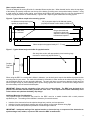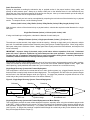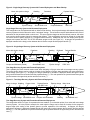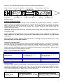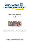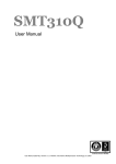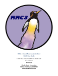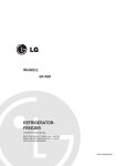
1
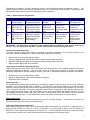
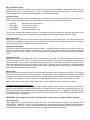
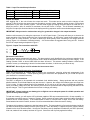
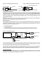
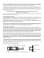
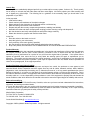
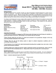
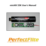
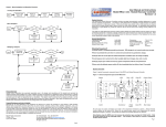
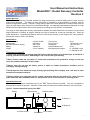
User Manual and Instructions Model RRC² - Rocket Recovery Controller Revision C System Overview The RRC2 Rocket Recovery Controller provides two stage barometrically controlled deployment of rocket recovery systems and equipment. Two-stage (or dual) deployment is preferable to single parachute or streamer recovery systems for high-power rocketry. Recovery of large, heavy rockets with a small parachute or streamer alone does not supply enough drag to safely recover the rocket without damage. An adequately sized parachute deployed at a high altitude may cause the rocket to drift out of the launch area, making recovery difficult if not impossible. Two stage (or dual) deployment recovery systems either separate the rocket airframe into two sections or eject a small drogue parachute or streamer at apogee, allowing the rocket to descend at a rapid yet controlled rate. When the rocket descends to a predetermined altitude above its initial launch elevation, it then deploys the main parachute, allowing the rocket to make a safe landing. Specifications Operational range Arming mode Minimum altitude for arming Battery Weight 0-25,000 ft. MSL barometric 300 ft. AGL onboard 9V 3.4 oz. w/battery Test Current Firing Current Dimensions Nominal Battery load Main deployment ranges 80 µa 1.25 amps @ 1 sec 1.30" W x 5.9" L 15ma Hi: 1000/500 ft. AGL Lo: 800/300 ft. AGL IHandling PrecautionsI IThese units are sensitive to damage from ESD (electro-static discharge) and should always be handled in a properly grounded environment. ESD damage is not covered under your warranty. INever directly handle the unit when it is armed and connected to live pyrotechnic charges as this may cause the premature detonation of the charges. IAlways allow the unit and the battery system to adjust to ambient temperature conditions prior to connecting, arming and flying. IAvoid exposure of an armed unit to high intensity light (including direct sunlight), heat, cold, wind, or other extreme environmental conditions. IAlways prepare your rocket and recovery system components with the unit powered off. Never cycle the power switch off, then immediately back on. Always allow at least 10 seconds prior to restoring power. Operational Overview Figure 1 depicts the general component layout of the RRC2 Rocket Recovery Controller. The unit is designed for several different modes of operation. Selection of these modes is made by the switches located on the circuit board. Figure 1 - General component layout of the RRC² Battery Microcontroller LED Pressure sensor + J1 (Output 1) + J2 (Output 2) J3 (Power switch) Piezo Beeper Switch Bank 1 The switches are labeled 1 through 5 accordingly, switch 1 being the leftmost switch as illustrated in figure 1. The ON/OFF position is also labeled, with the ON position being UP, the OFF position being DOWN. The following table describes the switch functions and the corresponding modes of operation: Table 1 - Switch functions and positions Func. On Pos. Off Pos. Switch 1 Main deployment altitude selection Stage 2 (J2/Main) deploys at 1000 ft. (SW.5 OFF) or 800 ft. AGL (SW.5 ON) Stage 2 (J2/Main) deploys at 500 ft. (SW.5 OFF) or 300 ft. AGL (SW.5 ON) Switch 2 Dual Deploy selection or Redundant Apogee Redundant apogee deployment operation (Stage 2/Main fires at apogee and overrides SW.1 & SW.5 setting) Standard two stage deployment operation (Stage 2/Main altitude selected by SW.1 & SW.5 settings) Switch 3 Mach delay timer selection 4 seconds of delay time is added to the mach delay timer total 0 seconds of delay is added to the mach delay timer total Switch 4 Mach delay timer selection 8 seconds of delay time is added to the mach delay timer total 0 seconds of delay is added to the mach delay timer total Switch 5 High or Low range Main deployment Lo-range Stage 2 (J2) deployment altitudes are selected (800 or 300 ft) based on SW.1 Hi-range Stage 2 (J2) deployment altitudes are selected (1000 or 500 ft) based on SW.1 IMPORTANT – The Mach Delay and High/Low range settings (SW. 3/4/5) MUST be made prior to powering up the unit. They are read at power up ONLY. Set ALL switch positions prior to turning the unit on. Standard two-stage deployment Two-stage recovery of high power rockets is preferable as previously described in the "Overview" section of this document. Operational progression of standard two-stage deployment is as follows: • • • • Initial launch, boost and coast phases of flight Apogee of flight detected, airframe separation or drogue chute/streamer deployed Rapid/controlled descent phase to pre programmed second-stage deployment level Main parachute deployment and touchdown Single-Stage / Redundant Apogee Deployment Single-stage deployment has its own set of advantages when the launch site size or weather conditions permit main parachute deployment at apogee. They are much simpler in design and are simpler to operate and prepare. Redundant apogee mode fires both charges at apogee (1 sec apart). Single-stage deployment operation is as follows: • • • Initial launch, boost, and coast phases of flight Apogee of flight detected, main parachute/streamer deployed Slow descent and touchdown Mach Delay timer For high-performance rocket flights approaching or exceeding the speed of sound (mach), the unit can be configured to employ a time delay just after lift-off is detected. This time delay prevents the possibility of premature apogee detection caused by the high/low pressure effects present along the rocket airframe during transition into and out of mach. During the time delay, all barometric samples from the sensor are ignored so these pressure effects cannot falsely trigger the apogee charge. After the expiration of time delay, normal barometric sampling resumes. The unit can be programmed for 4 seconds (SW.3 ON / SW.4 OFF), 8 seconds (SW.3 OFF / SW.4 ON), or 12 seconds (SW.3 ON / SW.4 ON) of total delay. It is recommended to use the mach delay at velocities of 0.8 mach or above. Modes of Operation The RRC² has several distinct modes throughout the course of its normal operation. These modes of operation are easily identified by the piezo beeper and the status LED. Power-up switch position annunciation After initially powering on the RRC² unit, it will annunciate (beep) the positions of all 5 switches in numerical order (1 through 5) with a series of '0's and '1's. A zero is a long beep, a 1 is a short beep A switch in the OFF position will beep as a '0', and a switch in the ON position will beep as a '1'. The LED flashes at a fast rate of 5 times per second. This annunciation allows you to double check the altimeter switch settings once inside the rocket. 2 Baro initialization mode After the switch position annunciation, the unit goes through a 15-second initialization and start-up delay. The LED flashes at a fast rate of 5 times per second. There is no audible sound from the piezo beeper. This start-up delay allows stabilization of the electronics and establishes an initial barometric history. Pre-launch mode After the 15-second power up and initialization delay, the unit goes into the pre launch mode. The LED will flash at a slow 2 second rate, and the piezo beeper will indicate the continuity of the ejection charges as follows: • • • • Long Beep 1 Short Beep 2 Short Beeps 3 Short Beeps No continuity on either channel Continuity on channel 1 Continuity on channel 2 Continuity on channel 1 & 2 The unit also monitors the barometric sensor for a change of 300 feet in elevation to determine the launch of the rocket. After this change, the unit transitions into mach delay mode (if selected) or apogee detection mode. Mach Delay mode When either SW. 3 or SW. 4 is in the ON position, the unit will enter the mach delay mode. The LED flashes again at its fast rate of 5 times per second. There is no audible sound from the piezo beeper. After the expiration of the mach delay (if selected), the unit transitions into apogee detect mode. Apogee Detection Mode At this point, the RRC² has detected launch and is in flight. The LED continues to flash at its fast rate of 5 times per second. The piezo beeper will beep at a fast rate of ½ second. During this mode the unit is sampling for apogee (indicated by an increase in pressure). When this pressure increase is detected, the unit transitions into deployment mode. Deployment mode Now that the unit has detected apogee, it will fire the channel 1 (J1) output. The LED will continue to flash at its fast rate of 5 times per second. There is no output from the piezo beeper. If the unit was set to operate in standard dual deployment mode, it will continue to sample barometric pressure until it is either 1000, 800,500, or 300 feet above the initial launch elevation before firing the channel 2 (J2) output. Otherwise the unit is operating in redundant apogee mode, and it will then fire the channel 2 output immediately following the channel 1 output. After the unit has fired both output channels, it transitions into report mode. Report mode After deployment of the recovery system, the unit will report the peak altitude it measured during flight. The LED will continue to flash at its fast rate of 5 times per second. The piezo beeper will continuously annunciate the peak altitude by beeping out the individual digits of the measurement. Depending on the peak altitude, the unit will annunciate 3, 4, or 5 digits. For example, let’s say the rocket flew to a peak altitude of 1230 feet. The unit would beep as follows: Beep...pause…Beep, Beep…pause…Beep, Beep, Beep…pause…Beeeeeeeeeeep…long pause….(repeat) Test Mode Operation and Diagnostics The unit can also be placed into a test mode to verify the basic integrity of the unit, and also to ground test e-matches, igniters, ejection charges, or recovery system designs. To place the unit into a test mode, toggle either SW. #1 or SW. #2 during the power up and initialization period according to the test you'd like to run. Toggling SW. #1 will set the unit into input test mode. Toggling SW. #2 will set the unit into output test mode The unit will continue to operate in the test mode selected until it is powered off. IMPORTANT: After selecting a test mode, you must power off the unit prior to flight or additional testing. Input Test mode After toggling SW. #1, the unit will enter the input test mode. This mode verifies the integrity of all the inputs to the microprocessor. Whenever an input is in the ON position, the unit will beep out a digit to indicate operational integrity of the input (see Table 2). The test mode scans and reports the inputs starting with the lowest value first (SW. 1). Lower value switch positions and inputs take priority over higher position switches and inputs. 3 Table 2 - Input Test mode beep indications 1 Beep 2 Beeps 3 Beeps 4 Beeps SW. #1 in the ON position SW. #2 in the ON position SW. #3 in the ON position SW. #4 in the ON position 5 Beeps 6 Beeps 7 Beeps SW. #5 in the ON position J1 continuity J2 continuity Output Test Mode After toggling SW. 2, the unit will enter the output test mode. This mode can be used to test the integrity of both outputs (J1 and J2) and to also ground-test your pyrotechnic e-match, igniter, flashbulb, ejection charge, or ground test deployment of your entire recovery system. The test mode begins by beeping the piezo beeper at a fast rate of 5 beeps per second. After 10 seconds of countdown, the unit will fire the J1 output. This is followed immediately by firing the J2 output (this functions identical to the deployment firing sequence used in the redundant apogee mode). IMPORTANT: Always exercise caution when using live pyrotechnic charges in the output test mode. Another useful accessory for testing the outputs are 12 volt DC panel lamps. The lamps will allow you to observe the proper operation of the outputs without the use of pyrotechnic devices. An LED with a current limiting resistor can be used in place of a lamp; however, you have to observe the diode polarity when connecting to the output terminals (refer to Figure 1 for orientation of terminal polarity) . A 470 ohm resistor is suggested when using an LED. Connect the LED for output testing as depicted in Figure 2. Figure 2 - Output Test connections with LED J1 or J2 (+) (-) Barometric Limits Alarm The unit also features a barometric limit alarm. This alarm mode is easily identified by the continuous actuation of the piezo beeper. While the unit is in the pre-launch mode it tests the barometric sensor reading for basic integrity. If the reading is below 0' MSL or above 14000' MSL the alarm will sound. This extreme reading indicates a failed sensor (unless of course your attempting to launch from those base elevations, in which case you cannot do so). IMPORTANT: Do not fly the unit if it activates the baro sensor alarm. Wiring / Mounting and Construction Considerations There are several factors to consider when it comes to the construction, mounting, wiring and arrangement of the RRC² in your rocket airframe. Careful planning during the construction and preparation of your rocket will improve your chances for a successful recovery. Onboard Battery Connections The RRC² is designed to be operated with a standard 9-volt alkaline battery. Always purchase and use premium alkaline batteries; 9-volt Nicad batteries may also be used -- however, the voltage of this battery type can range from 7.2 to 8.4 volts. A higher voltage Nicad is more desirable, as 7.2 volts is on the very edge of operational acceptance. When your battery voltage is too low, the continuity circuit will fail to operate and will not report (beep) the status of the ejection charges. This is a good indication that it's time to change your battery. IMPORTANT: Always load test your battery prior to flight to ensure adequate power for reliable operation and ignition of the ejection charges. To load test a battery, you will require a DC multimeter capable of DC amp measurement with a 10 amp capability. A 9-volt battery can easily source in excess of 5 amps. Briefly connect the meter leads across the battery terminals to measure the DC current capacity. If the measurement is close to or drops below 2 amps, do not use the battery. Some batteries have built in testers, however it is still recommended that a meter be used for testing. The battery clip hardware is designed to hold the battery tightly. The best method is to first push the battery inside the clip without connecting the battery terminals (see Figure 3). Once the battery is clipped into place, push the battery forward into the circuit board terminals. Next bolt on the battery end clip hardware included with your RRC² (#4 screw, 2-#4 nuts, washer & lock washer) as shown in Figure 4. Secure the end clip firmly against the battery. 4 Figure 3 - 9 volt battery insertion (side view) Figure 4 - Battery end clip placement (side view) Bracket (large hole on top) Push forward Terminals #4 nuts Lock washer Washer #4 screw External Battery Connections Though the unit is intended to operate with an onboard 9-volt battery, the user may elect to power the RRC² with an external battery source. The voltage requirement for this battery source is 7.5 to 9 volts. DO NOT EXCEED 9 VOLTS. A standard 9-volt battery clip with wire leads easily mates to the onboard 9 volt battery clip (note: when connected in this manner, reverse the wire leads to maintain the correct polarity). The user must also adequately size the current capacity of the battery system. Nominal load during operation is about 15 ma; and during output firing, the unit requires upwards of 2 amps. IMPORTANT: Inadequate sizing of an external battery system will damage or cause the unit to malfunction. Always pre-test your external battery system design prior to launch. Wiring Connections Figure 5 depicts the standard wiring connections; J1 connects to the apogee deployment charge, J2 connects to the main deployment charge, J3 connects to an external user supplied power switch. This switch is best located on the exterior of the rocket airframe; however, it can be placed at a convenient spot inside the airframe as well. There are several options you can use for the power switch: • • • • A small 3-pole slider switch A locking toggle switch A normally closed phono jack (open circuit when a phono plug is inserted, closed circuit when removed) A pair of wires run through the airframe that are twisted and taped together, then fed back into the airframe Figure 5 - Standard Wiring diagram J1 Apogee deployment charge Main deployment charge J2 J3 On/Off switch For the most failsafe wiring scheme to minimize the possibility of premature firing of the ejection charges, wire in a pair of normally closed phono jacks or disconnect switches in series with the leads of the deployment charges. The phono jack or switch serves as a disconnect between the unit and the deployment charges. (Note: Although the aforementioned failsafe wiring scheme provides the most secure means for prevention of premature firing of ejection charges, it's the opinion of Missile Works Corporation that the use of any extra mechanical switches or connections increases the likelihood of failure due to poor, or flight-induced, intermittent connections) Mounting Considerations The RRC² can be mounted in several effective ways. With some forethought and design, you can construct a system in which the unit is easily mounted and removed, or even shared among several different rockets. The following describes just one of several possible configurations for mounting. 5 38mm coupler tube mount The unit is designed for a snug fit inside of a standard 38mm coupler tube. When inserted into the tube, the top edges of the battery clip actually compress over the top of the battery, providing even more positive battery retention. Using a small section of 38mm coupler tubing, some 38mm body tubing and centering rings, the unit can be adapted to virtually any payload section or electronics bay. Figure 6 and 7 depict a typical 38mm tube mounting system. Figure 6 - Typical 38mm coupler tube mounting system #4 allthread rod epoxied in place against ply support strips 1/8" ply support strips for #4 allthread (typical) (top strips recessed to allow battery clearance) Drogue side bulkhead (epoxied in place) with allthread nutted through bulkhead and epoxied Main side bulkhead 38mm coupler tube (approximately 6.5" - 7" long) Figure 7 - Typical 38mm body tube holder for payload section 38m body tube section with appropriately sized centering rings mounted in rocket body payload section Coupler Tube with RRC² When using the RRC² in a rocket that is 38mm in diameter, you obviously won't require the additional payload section mounting tube for your rocket. The main side bulkhead is removable, to allow access to the electronics and wiring. It can be attached with #4 nuts and protruding allthread. The main seal does not require an absolute air-tight seal, but should be tight enough to prevent damage from ejection charge gases and residue. Be sure that the drogue side of the rocket always uses the sealed bulkhead plate. IMPORTANT: Please note the orientation of the unit in the rocket airframe. The RRC² was designed to be placed in the airframe with the battery towards the nose cone. This improves the CG/CP relationship of the rocket vehicle and optimizes the battery clip design. Additional Mounting Considerations The payload section or electronics bay used for the RRC² must be a sealed chamber with a static pressure equalization port. The sealing of the chamber is necessary for several reasons: • • • Isolation of the electronics from the ejection-charge heat, residue, and over-pressure Isolation from the aerodynamic pressure and vacuum effects on the rocket airframe during flight Provides uniform static pressure equalization to ambient flight conditions IMPORTANT: Inadequate sealing of the payload section or electronics bay, or exposure of the electronics to ejection-charge heat, residue, or pressure will cause the RRC² to malfunction. 6 Static Pressure Ports Equally as important as sealing the electronics bay or payload section is the proper location, sizing, quality, and quantity of static pressure ports. Always try to locate a static port on the airframe where it is not obstructed by any object that may cause turbulence upstream of the airflow over the port. Also try to locate the static port as far away as possible from the nose cone or body transition sections. The sizing of the static port hole can be accomplished by computing the total volume of the electronics bay or payload section. To compute volume, use the following formula: Volume (cubic inches) = Bay Radius (inches) X Bay Radius (inches) X Bay Length (inches) X 3.14 With the known volume of the electronics bay or payload section, calculate the required nominal diameter for a single static port: Single Port Diameter (inches) = Volume (cubic inches) / 400 If using a multi-static port configuration, calculate the diameter for each static port: Multiport Diameter (inches) = Single port diameter (inches) / [ # of ports / 2 ] The static port requires smooth, clean edges around the opening. Although a single static port is adequate, multiple ports null out undesirable pressure effects caused by strong wind gusts or unstable flight profiles. When using multiple static ports, always use a minimum of three. Always space them equally around the rocket airframe, and keep them all in-line horizontally. IMPORTANT: Improper sizing of the static port(s) could induce adverse operation of the unit. Undersized ports will cause a pressure equilibrium lag and subsequent late event operation. Oversized ports tend to increase the risk of premature deployment due to pressure anomalies during boost caused by atmospheric conditions, airframe turbulence or velocity induced pressure spikes. Recovery System Design Considerations The following recovery system designs represent some of the most common implementations used in hobby rocketry. These are included as construction guidelines only, and all can have several variations applied to them. Again, with careful planning, quality materials and construction, your increase your chances for a successful recovery. Single-Stage Recovery System with Forward Deployment This configuration is best used for rockets that have no motor ejection system (e.g., plugged forward closures) or for those that wish to employ totally electronic based deployment. This configuration can also utilize two ejection charges and be flown in the redundant apogee mode (see Figure 8). At apogee the parachute is ejected forward out of the rocket body at the junction between the nose cone and the airframe (⇑). Figure 8 - Single Stage Recovery System / Forward Deployment Bulkhead Wadding Parachute ⇑ RRC² unit Ejection charge Shock/Bridle cord Single-Stage Recovery System with Forward Deployment and Motor Backup This configuration provides the most reliable deployment system, especially when using the redundant apogee mode of the RRC². When configured in this manner, the user can employ triple redundancy (motor ejection charge and the dual redundant charges of the electronics). It is probably the easiest to retrofit into existing rocket airframes as well (see Figure 9). At apogee the parachute is ejected forward though the rocket body at the junction between the rocket body and the payload section coupler (⇑). 7 Figure 9 - Single-Stage Recovery System with Forward Deployment and Motor Backup Motor with ejection charge Wadding Parachute Payload Section ⇑ Ejection charge Shock/ Bridle cord Coupler/Bulkhead RRC² unit Single Stage Recovery System with Rearward Deployment This configuration can be implemented with or without motor backup. One major advantage with rearward deployment recovery systems is what's referred to as the "anti-zipper" design. The tail section coupler and bulkhead is the point of attachment for the parachute bridle or shock cord. The motor ejection charge can also be utilized; however, the rocket must vent the ejection gases forward to separate the airframe. This configuration can also be utilized for rockets that use motors with no ejection charges (e.g., plugged forward closures). Additionally the user can employ dual ejection charges and operate the RRC² unit in the redundant apogee mode (see Figure 10). At apogee the parachute is deployed rearward at the body junction between the tail section coupler and the payload section (⇑). Figure 10 - Single-Stage Recovery System with Rearward Deployment Motor with ejection charge Parachute ⇑ Coupler and Bulkhead (vented) Wadding Shock/Bridle cord Bulkhead Ejection charge Payload Section RRC² unit Two-Stage Recovery System with Forward Deployment This is probably the most common method used when designing or flying a rocket with a two-stage recovery system. The motor ejection charge can be used as a backup for the apogee or drogue stage providing even more redundancy for the design (see Figure 11). At apogee, the drogue parachute or streamer is deployed forward through the lower body junction between the tail section and the payload section (⇑). The main parachute is ejected forward through the junction between the upper body section and the nose cone (↑). Figure 11 - Two-Stage Recovery System with Forward Deployment Motor w/ charge Wadding Ejection charge Drogue 'chute ⇑ Shock/Bridle cord Payload Section with RRC² unit Ejection charge Couplers with Bulkheads Main 'chute Wadding ↑ Shock/Bridle cord Two-Stage Recovery System with Forward and Rearward Deployment The configuration shown in Figure 12 represents the best method (in our humble opinion) for a rocket with a two-stage recovery system. As in the previous example, the motor ejection charge can be used as a backup for the apogee or drogue stage (with venting of the ejection gases to provide separation of the airframe). At apogee, the drogue parachute or streamer is deployed rearward through the lower body junction between the tail section and the payload section (⇑). The main parachute is ejected forward through the junction between the upper body section and the nose cone (↑). 8 Figure 12 - Two-Stage Recovery System with Forward and Rearward Deployment Motor w/ charge Drogue 'chute ⇑ Coupler with Bulkhead (vented) Wadding Shock/Bridle cord Payload Section with RRC² unit Ejection charge Couplers with Bulkheads Wadding Main 'chute ↑ Shock/Bridle cord E-matches and Ejection Charges The topic of e-matches and ejection charges is often overlooked and not given a proper evaluation. The ejection charge is as critical a component as the electronics. Improper selection or application of e-matches can result in failure of the recovery system and total loss of the rocket. The following text will make some very specific recommendations which you should seriously consider when selecting, constructing, and ultimately flying with electronic deployment systems. IMPORTANT: Always ground test the type of e-match you'll be using under actual flight conditions prior to committing to flight. Improper selection of an e-match will result in a malfunction. Always use an e-match that is suited for the firing conditions of the RRC² unit (e.g., do not use a match with very low current or very high current requirements). Always check your e-match, igniter, or flash bulb devices for continuity and proper resistance prior to using them under testing or actual flight conditions. Selecting an adequate E-match The RRC² has been tested and flown with several commercially available e-matches. It has also been successfully tested and flown with AG-1 flashbulbs, and custom made .003" nichrome bridgewire ejection charges. This, however, is a just a small sampling compared to what is commercially available. When selecting an alternative e-match supplier, refer to the "Specifications" section for the typical test current and firing current of the RRC². Refer to Table 3 for adequate commercial e-match suppliers for the RRC². Table 3 - Recommended E-match suppliers Manufacturer Daveyfire Inc. 7311 Greenhaven Dr, Suite 100 Manufacturer Address Sacramento, CA 95831-3572 Phone Numbers Tel: 916.391.2674 Fax: 916.391.2783 Resistance 1.6 ± 0.3 ohms Test Current 10 ma (0.010 amp) maximum Recommended Firing Current 0.6 amp minimum OXRAL Inc. (Luna-Tech) PO Box 160 Owens Cross Roads, AL 35763 Tel: 205.725.4226 Fax: 205.725.4811 2 ohms (nominal) 25 ma (0.025 amp) maximum 0.5 amp minimum Ejection charges The ejection charge consists of a small quantity of black powder which when ignited produces enough gas pressure to expel the recovery system from the body of the rocket. You can either make your own ejection charges or purchase commercially available ejection charge systems. Robby's Rockets provides two ejection charge systems, one single use, the other a reloadable system. Refer to Table 4 for more information. Table 4 - Commercial Ejection Charge suppliers Robby's Rockets Disposable Ejection Charges P.O. Box 171 10 prewired AG-1 bulbs in cardboard tubes, 1 gram measuring cup, end caps Elkhart, IN 46515 and mandrel 219.679.4143 L.E.S. Kits (Loadable Ejection System) Reusable aluminum charge holder, 10 prewired AG-1 bulbs, 1 gram measuring cup, end caps and mandrel 9 There are several methods for constructing your own ejection charges. First you'll need to acquire some black powder locally. It is recommended that you use FFFF (4F) grade, however FFF (3F) powder can be used. Another commercially available powder is called Pyrodex, which should not be substituted for black powder. The following formula represents a general rule of thumb for calculating the required amount of black powder for a given airframe. Factors such as a tight-fitting nose cone or coupler, as well as a tight-fitting parachute or streamer, can affect the performance of an ejection charge. It's always better to have a little extra black powder, as not enough could possibly result in deployment failure. Black Powder (grams) = Compartment Diameter (inches) X Compartment Diameter (inches) X Compartment Length (inches) X .006 Unless you've got a reloading scale, the easiest method to measure black powder is to purchase a set of black powder measuring cups from your local firearms dealer. Quick and Easy Ejection Charge One easy method for constructing charges is to use aluminum foil and some masking tape. Start with a small square of aluminum foil (about 4" to 5" square). Form a small "thimble" by molding the foil over your index finger. Next measure in the necessary amount of black powder. Insert your e-match or flashbulb into the black powder. IMPORTANT: Be sure that the leads to the flashbulb or e-match are COMPLETELY INSULATED, otherwise the leads could short out on the foil, causing the charge to fail. Finish the charge by compressing the remainder of the foil around the black powder and e-match/flash-bulb. Seal the end with a wrap or two of masking tape. Small plastic "Baggies" can also be used by snipping off a corner of the bag, filling it with black powder, loading your E-match, then securely sealing the bag with tape. Reusable ejection charge system Another method is to construct a set of reusable canisters from 1/2" launch lug tubing and 1/2" wooden dowel. First cut a small length of launch lug tubing. The length of the tubing will depend on the amount of black powder necessary and what you're using to ignite it. A flashbulb requires much more real estate than an e-match. After properly sizing the tubing, take the 1/2" dowel and cut a thin slice (about 1/8" thick) off the end. Take this slice of dowel and epoxy it into one end of your tubing. When the epoxy has cured, drill a small hole through the slice of dowel. The hole diameter will depend on the size of the wire leads you'll be using. The canister is now complete. Place the flashbulb or e-match into the canister, pulling the wire leads through the small hole. Seal this hole with a hot glue gun or silicone. Fill the canister with the necessary amount of black powder. Gently tamp the black powder against the bulb or e-match with a small length of the 1/2" dowel. Next, tamp in a small piece of tissue paper, then seal the canister by melting some candle wax over the tissue. Be careful with the open flame of the candle around the black powder. After firing the charge, the wire leads and bulb/match remains can be removed and the canister reloaded for another use. A convenient means of holding these charge canisters is to use a 1/2" CPVC end cap with a small hole drilled through the bottom for the wire leads. Fasten the end cap securely on a bulkhead surface with a screw and/or epoxy. Place a few wraps of masking tape around the outside of the canister (if required), pull the wire leads through the hole and you'll get a very snug fit in the CPVC end cap (see Figure 13). Figure 13 - Reusable ejection charge system Black powder Flashbulb or e-match Wire leads Bulkhead plate Hole for wire leads Tissue/wax plug Dowel slice with hole Glue or Silicone seal 1/2" CPVC end cap 10 Launch Day Now that you have methodically designed and built your rocket and its recovery system, it's time to fly. There's usually lots of activity on a launch day with other fliers and other rocket flights. It's best to prepare your rocket carefully and not to bypass any critical steps. The following list is a guideline of the necessary steps you should take in the preparation of your RRC². At the prep table • Load test the battery • Check continuity and resistance of the ejection charges • Mount and secure the electronics in the payload section or altimeter bay • Make final wiring connections to the electronics • Prepare and pack the recovery components (parachutes, wadding, heat shields) • Assemble the rocket and check all deployment coupling junctions ensuring a snug and adequate fit • Arm the electronics and verify switch positions and ejection charge continuity • Disarm the electronics, prepare and load the rocket motor At the Pad • Place the rocket on the launch rod or rail • Insert the igniter in your rocket motor • Verify continuity of the motor igniter (if possible) • Arm the electronics and re-verify switch settings and ejection charge continuity • Snap a few photos, then RELISH IN THE CULMINATION OF ALL YOUR WORK AND PREPARATION Product Warranty Missile Works Corporation has exercised reasonable care in the design and manufacture of this product and warrants the original purchaser that the RRC² Rocket Recovery Controller is free of defects and that will operate at a satisfactory level of performance for a period of one year from the original date of purchase. If the system fails to operate as specified, then return the unit (or units) within the warranty period for repair or replacement (at our discretion). The system must be returned by the original purchaser, and be free of modification or any other physical damage which renders the system inoperable. Upon repair of replacement of the unit, Missile Works Corporation will return the unit postage paid, to the original purchaser. Product Disclaimer and Limit of Liability Because the use and application of this equipment are beyond our control, the purchaser or user agrees to hold harmless Missile Works Corporation and their agents from any and all claims, demands, actions, debts, liabilities, judgements, costs, and attorney fees arising out of, claimed on account of, or in any manner predicated upon loss or damage to property of, or injuries to or the death of any and all persons arising out of the use this equipment. Due to the nature of electronic devices, the application and environments for those devices, the possibility of failure can never be totally ruled out. It is the responsibility of the purchaser or user of this equipment to properly test and simulate the actual conditions under which the device is intended to be used to ensure the highest degree of reliability and success. Rules to live and fly by 1. Before you use the RRC² Rocket Recovery Controller, make sure you have read and understand all the instructions, operations, and warnings contained herein. 2. Do not alter the system in any way, as this voids the warranty and could render the system inoperable or unreliable. 3. Always fly within the guidelines established by either the National Association of Rocketry or the Tripoli Rocketry Association whenever you participate in hobby rocketry activities. Missile Works Corporation P.O. Box 740714 Arvada CO 80006-0714 Tel: 303.426.1462 Fax: 303.426.1428 On the World Wide Web @ www.missileworks.com Copyright 2000 by Missile Works Corporation. All rights reserved 11