1
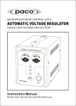
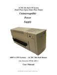
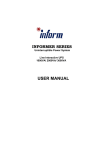
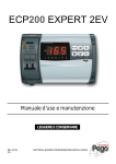
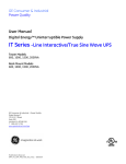
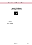
U
P
U n i n t e r r u p t i b l e
P o w e r
S
S y s t e m
500VA/ 650VA/ 800VA
User’s Manual
IMPORTANT SAFETY INSTRUCTIONS
SAVE THESE INSTRUCTIONS
●WARNING (SAVE THESE INSTRUCTIONS): This manual contains important instructions
that should be followed during installation and maintenance of the UPS and batteries.
●WARNING (Controlled Environment) : Intend for installation in a controlled environment.
●CAUTION: Do not dispose of batteries in a fire, the battery may explode.
●CAUTION: Do not open or mutilate the battery, released electrolyte is harmful to the skin
and eyes. It may be toxic.
●CAUTION: A battery can present a risk of electric shock and high short circuit current. The
following precaution should be observed when working on batteries
Remove watches, rings or other metal objects.
Use tools with insulated handles.
Wear rubber gloves and boots.
Do not lay tools or metal parts on top of batteries.
Disconnect charging source prior to connecting or disconnecting battery terminals.
●Servicing of batteries should be performed or supervised by personnel knowledgeable of
batteries and the required precautions. Keep unauthorized personnel away from batteries.
●When replacing battery, replace with same type.
●Do not to addition battery for UPS.
TABLE OF CONTENTS
INTRODUCTION………………………………………………………….……………………………..1
IMPORTANT S AFETY INSTRUCTIONS………………………………………………………..………1
1. PRESENTATION………………...………….……………………………..…,.………………………2
2. INSTALLATION….………………………………………………………...…………………………3
3. OPERATION………………………………………………………………...………………………3
4. ALARMS………………………….….…………………………………………..……………………3
5. SOFTWARE AND INTERFACE PORT…………………………………………………………………4
APPENDIX A TROUBLESHOOTING……………………………………...……………..…………………5
APPENDIX B SPECIFICATIONS……..…………………………………...……………..………………5
Please read and save this manual !
Thank you for selecting this uninterruptible power system (UPS). It provides you with a
perfect protection for connected equipment. The manual is a guide to install and use the
UPS. It includes important safety instructions for operation and correct installation of the UPS.
If you should have any problems with the UPS, please refer to this manual before calling
customer service.
1
1. PRESENTATION
The UPS is a standby uninterruptible power system (UPS). When utility input is normal, the
UPS would provide surge protection and energy to charge the internal battery. If the utility
input is abnormal, the UPS can supply AC power to the load immediately.
(1). Utilizes microprocessor based controls, it will minimizes the dependency on hardware.
Beside this, it maximizes system flexibility and optimizes the assurance of reliability.
(2). Automatic frequency selection to match with utility power.
(3). Hi-grade battery charger to prolong battery’s life and fully charge the battery.
(4). With actual overload protection both in line and battery mode.
Front View
POW ER
OVER LOAD
BATT CHECK
ON/OFF/TEST
BAZZER STOP
1.1 “POWER” indicator (Green): The indicator will illuminate
when the utility input is normal.
The light becomes flash when working at back-up mode.
1.2 “OVERLOAD” indicator (Red): The indicator will
illuminate when the output power is overload from the unit.
1.3 “BATTY” indicator (Red): The indicator
illuminates when the battery is no longer useful and must
be replaced.
1.4 “ON/OFF/TEST” button: No matter the UPS is
plugged in or not. Press the “ON/OFF/TEST”
button till the beep stop to turn on or turn off the UPS.
It also enables the UPS self-test by press the bottom less
than 1 second.
1.5 “BUZZER STOP” button
In back up mode, press the bottom about 1 second to
enable the UPS silence function.
Rear View
1.6 Outlet Socket
1.7 Communication Port*
1.8 Internet/Tel/Modem Port*
1.9 Bypass Outlet (U.S. socket only)
1.10 Input Fuse
1.11 AC Input
*Can be removed if not desired
2
2. INSTALLATION
2.1 Inspection: Inspect the UPS upon receipt. The packaging is recyclable; save it for reuse
or dispose of it properly.
2.2 Placement: Install the UPS in controlled area with adequate air flowing and free of
excessive dust. Do not operate the UPS at outdoor area.
2.3 Utility Power: The input power cord needs to connect the rear inlet socket of the UPS
and plug into a socket on the wall. Please notice the voltage of utility power should match
with the UPS. (For example, the rating voltage of UPS is 110V/(220V), the input utility power
should be the same as 110V/(220V) .)
2.4 Connection: The employed equipment’s power cords (such as computer) are plugged
into the sockets on the rear panel.
Attention: Service personnel installable.
Attention: With the installation, the overall leakage current of the UPS connected consumer
shall not exceed 3.5mA.
Attention: A block diagram of this unit is attached to the user’s manual and to the installation
instruction.
3. OPERATION
3.1 Switch on: When utility input is connected to the UPS, press “ON” button at “OFF” mode
and keep pressing until the beep stops. After that, connect the electrical cords of the
equipment that is going to be used such as computer or monitor with the terminal at the rear
panel of UPS.
Attention: This unit is to operate by any individuals with previous training.
Attention: At “BACKUP” mode, UPS can be automatically turned off if none of the
connected loads is operating. (No Load shut down function)
CAUTION: Never connect a laser printer or plotter to the UPS with other computer
equipment. A laser printer or plotter periodically draws significantly more power than its idle
status, and may overload the UPS.
3.2 Switch off: Press the “OFF” button at “LINE” or “BACKUP” modes and keep pressing
more than 1 second to turn off the UPS.
3.3 Silence: When UPS is under “BACKUP” mode, press the “BUZZER STOP” button about
1 second to silence the audible alarm. (The function is disabled when UPS is under
condition of “LOW BATTERY” or “OVERLOAD”)
3.4 Self-test function: Press the “TEST” button at “LINE” mode about 1 second, UPS will
perform self-test procedure automatically.
4. ALARM
4.1 “BACKUP” (slow alarm): When the UPS is working under “BACKUP” mode, the UPS
would emit audible alarm. The alarm stops when the UPS is return to “LINE” mode
operation.
Attention: The alarm of “BACKUP” is going to beep every 2 seconds. (Slow-speed beep).
Attention: The UPS provides mute function for the warning. When the beeping sound
occurs, press "BUZZER STOP" to stop it; and press "BUZZER STOP" again to resume
the sound.
3
4.2 “LOW BATTERY” (rapid alarm): In the “BACKUP” mode, when the energy of battery
becomes to lower level. (about 20%~30%) The UPS beeps rapidly until the UPS shuts down
from battery exhaustion or returns to “LINE” mode operation.
Attention: The alarm of the batteries caused by low voltage beeps every 0.5 second.
Attention: The rapid alarm under “LOW BATTERY” condition cannot be muted.
4.3 “OVER LOAD” (continuous alarm): When the UPS is working under overload
condition (the connected loads exceed the maximum rated capacity), the UPS will emit
continuous alarm to warn an overload condition. In order to protect the unit and the loads,
the UPS will be automatic turn off. Please disconnect nonessential devices from UPS to
eliminate the overload alarm.
5. S OFTWARE
AND I NTERFACE
P ORT
5.1 Power Monitoring Software
The UPS-MON series software (or other power monitoring software) is applied standard
RS-232 interface to perform monitoring functions, and then provides an orderly shutdown of
a computer in the event of power failure. Moreover, UPS-MON displays all the diagnostic
symptoms on monitor, such as Voltage, Frequency, Battery level and so on. The software is
available for DOS, Windows 3.1x, Windows 95, Windows 98, Windows NT V3.5 or later,
Novell Netware, Linux, and others. Call your dealer for more information on computer OS
compatible solutions.
5.2 Interface Kits
A series of interface kits is available for operation systems that provide UPS monitoring.
Each interface kit includes the special interface cable required to convert status signals from
the UPS into signals which individual operating system recognizes. The interface cable at
UPS side must be connected to REMOTE PORT, at computer side can be either COM 1 or
COM 2. The other installation instructions and powerful features please refer to READ.ME
file.
CAUTION: Use only factory supplied or authorized UPS monitoring cable!
5.3 The characteristics of computer interface port
The computer interface port has the following characteristics:
The communication port on the back of the UPS may be connected to host computer. This
port allows the computer to monitor the status of the UPS and control the operation of the
UPS in some cases. Its major functions normally include some or all of the following:
To broadcast a warning when power fails.
To close any open file before the battery is exhausted.
To turn-off the UPS.
Some computers are equipped with a special connector to link with the communication port.
In addition, special plug-in cord may be needed. Some computers may need special UPS
monitoring software. Contact your dealer for the details on the various interface Kits.
4
APPENDIX A TROUBLESHOOTING
PROBLEM
POSSIBLE CAUSE
UPS cannot turn ON/OFF/TEST/SILENCE button
on
not pushed or push-time too
LED not light
short
Battery voltage less than 10V
PCB failure
Load less than 20W at battery
mode
UPS always at Power cord lose
battery mode
AC FUSE burn out
Line voltage too high, too low or
black out
PCB failure
Back up time too battery not fully charged
short
PCB failure
Buzzer continuous Overload
beeping
ACTION TO TAKE
Press
the
ON/OFF/TEST/SILENCE button
more than 1 second
Recharge the ups at least 6 hours
Replace the PCB, call for service
Normal condition, “No load
shutdown function” is active.
Plug in the power cord
Replace the AC fuse
Normal condition
Replace PCB, call for service
Recharge the UPS at least 6
hours
Replace PCB, call for service
Remove some loads
APPENDIX B. SPECIFICATIONS
OUTPUT
MODEL
Capacity
Bypass Capacity
No. of sockets
Voltage (on battery)
Frequency(on battery)
Transfer Time
INPUT
Voltage(single phase)
PROTECTION
Frequency
Unit Input
Overload Protection
Short Circuit
500
650
800
500VA
650VA
800VA
300VA
300VA
300VA
T wo U P S S o c k e t s a n d O n e B y p a s s
Socket
S i m u l a t e d s i n e wa v e a t
100V/110V/115V/220V/240V +/-5%
50 or 60Hz +/-0.3Hz
2/4 milliseconds, including detection
time
110V+20%/-15% at line input,
110V/115V/+/-20% at line input
220V+/-25% at line input,
240V+15%/-20% at line input
50 or 60Hz+/-10% ( auto sensing)
Fuse for overload & short circuit
protection
U P S a u t o m a t i c s h u t d o wn i f o v e r l o a d
e xc e e d s 1 0 5 % o f n o m i n a l a t 2 0
seconds, 120% at 10 seconds,
130% at 3 seconds
UPS output cut off immediately
5
BATTERY
Type
Sealed, maintenance-free lead acid
b a t t e r i e s , wi t h 3 - 6 y e a r s t y p i c a l l i f e t i m e
Battery Check
LED Indicators
Typical Recharge Time
(to 90% of full capacity)
Back up Time (minutes)
( P C wi t h 1 5 ” m o n i t o r )
Protection
PHYSICAL
N e t we i g h t K g ( l b s )
D i m e n s i o n ( m m ) W xD xH
INTERFACE
Dry contact
RS232
ALARM
Battery Back-Up
Battery Low
105% load
Overload
ENVIRONMENT
Ambient operation
Audible Noise
4 hours
10-25
15-30
18-33
minutes
minutes
minutes
Automatic self-test, Over discharge
protection, short circuit protection by
fuse
3.6(7.9)
3.7(8.1)
3.8(8.3)
70*297*195
(2.8*11.7*7.7)
S e n d s b a t t e r y l o w & p o we r f a i l u r e
s i g n a l s , a n d r e c e i v e s s h u t d o wn s i g n a l
from computer
D e t e c t b a t t e r y l o w, S c h e d u l e U P S
o n / o f f , A S i n p u t / o u t p u t p o we r s t a t u s
display
Slow beeping sound every 4
seconds(buzzer can be turn off by
pressing “buzzer stop” button)
Rapid beeping sound every second
Continue beeping sound every 4
seconds
Continue beeping sound, Overload
L E D A l wa y s O n
3 , 5 0 0 m e t e r s m a x. e l e v a t i o n , 0 - 9 5 %
h u m i d i t y ( n o n - c o n d e n s i n g wa t e r ) ,
0-40℃
<40dBA(1 meter from surface)
©2002.March. 05 Version 1.0 All right Reserved.
A l l t r a d e m a r k s a r e p r o p e r t y o f t h e i r r e s p e c t i v e o wn e r s . S p e c i f i c a t i o n s s u b j e c t t o
c h a n g e wi t h o u t n o t i c e .
6 6 1 - E K5 0 - 0 0 0
6