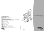
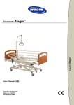
1
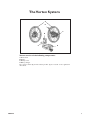
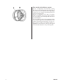
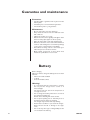
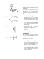
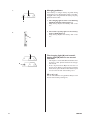
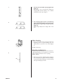
Vortex
User's manual
English
VORTEX
1
2
VORTEX
Vortex
You have now taken delivery of a new wheelchair with
Vortex. For optimal use and suitability to your needs,
we hope that your wheelchair has been tested for you
by an authorised person. This means that the wheelchair
has been adjusted according to your requirements, taking
into account your weight and other personal needs. We
presume that these adjustments have been made and that
you have also received instructions and advice on how to
use your wheelchair in your everyday life.
Please read through this instruction manual before starting
to use your Vortex wheelchair. It is full of good advice and
adjustment possibilities.
Vortex is a power driven auxiliary motor which is activated
by the handrims. Vortex has been tested and approved
at TÜV in Germany in combination with the following
wheelchairs: REA Comfort, Adapt, Spirea XLT, Rea Bellis
and Rrea 703 LX.
We hope that you will be fully satisfied with your Vortex
wheelchair.
NB!!!
!
Read the back page of this instruction manual. The text
covers a number of points regarding your own personal
safety. Please read it carefully!
Invacare Rea AB only takes responsibility for product
alterations carried out by personnel we authorise. We
reserve the right to make equipment and specification
changes without prior notice.
DELIVERY CHECK
Check that all components comply with the delivery note.
Any damage incurred during transport must be reported
immediately to the transport company. Retain all packaging
until the transport company has checked the consignment
and an agreement has been reached.
Please notify Scandinavian Mobility if an accident or similar
incident occurs when this product is used.
VORTEX
3
Contents
The Vortex system ...............................................................5–6
Assembly...............................................................................7–17
Transport and disassembly ............................................18-19
Technical specifications ......................................................... 20
Area of use ............................................................................... 21
Product description................................................................ 21
Guarantee and maintenance................................................. 22
Battery ................................................................................ 22-27
Troubleshooting ..................................................................... 28
Operating the wheelchair ..................................................... 29
Sound guide ............................................................................. 30
Guide to safe operation .................................................31-33
4
VORTEX
The Vortex System
A
E
F
B
C
D
Vortex consists of the following components:
A. Drive wheel
B. Battery
C. Battery cover
D. Battery charger
The control switch (E) and the battery holder (F) are located on the right-hand
drive wheel.
VORTEX
5
A
6
B
Two models of the Vortex system
Type A – is designed for users who have a strong
grip and cover long distances by themselves. Type A
has an assist ratio of 1.5. Of the total energy supply
required, the user supplies approximately 40% and
Vortex approximately 60%.
Type B – is designed for users with a somewhat
weaker grip. Of the total energy supply required,
the user supplies approximately 25% and Vortex
approximately 75%.
You can see which version you have simply by looking
at the handrims. Type A has polished/stainless steel
handrims and type B has black plastic covered ones.
There is also a number in the battery holder, e.g.
XA4G. If the fourth character is “G” you have type A
and if the fourth character is “H” you have type B.
VORTEX
Assembly
New chair with Vortex system
1.
The Vortex system and the wheelchair are delivered
in separate packaging.
A
Vortex wheels
1. Start by fitting the Vortex wheels to your
wheelchair. The wheels are quick release (QR).
2, Start by opening out the handle (A) for the quick
release mechanism (Figure 1).
2.
3. When you fit the right-hand wheel, you must lift
the wheelchair slightly with your left hand whilst
keeping your right hand under the battery holder
to prevent it rotating (Figure 2). Then insert the
QR axle (B). Figure 3.
It is very important that the axle is pushed in
far enough. If not, the QR axle may break. See
figure 3 (D).
3.
D
VORTEX
7
1.
Cable
A
1. Then, cable (A), which hangs loose in the righthand wheel, must be put into the socket (B).
It is important that the cable is placed so that
the arrow on the cable is above the small dash
on the socket.
B
2.
Battery
2. The battery supplied should already have been
charged. Remove the protective cover and simply
place the battery into the battery holder as
indicated in figure 2.
8
VORTEX
1.
Anti-tip device
1. The anti-tip device is fitted on the wheelchair
when delivered and must always be used on a
Vortex wheelchair. If you have ordered an Adapt
or XLT chair and requested fitting of the Vortex
wheels in a special position, you may find that a
shorter type of anti-tip device has been fitted on
the right-hand side. This has been done seeing
as the original anti-tip device interferes with the
battery holder. See the illustrations above.
Adapt
2.
XLT
1.
Vortex as an assembly set for previously delivered wheelchairs
1. If you have bought the Vortex system only –
without a chair – there are a few components you
must fit to enable you to fit the Vortex wheels
to your wheelchair.
A
2.
Fitting the centre plate
B
VORTEX
Spirea
2. If your Spirea chair does not have a position
plate, you must fit one to it. The position plate is
included in the assembly set.
Start by loosening the two screws (A) and
removing the drive wheel attachment.
The position plate is attached with two bolts (B)
as shown in the diagram.
9
3. Then fit the centre plate (C) as shown.
3.
C
A
4.
Adapt (diagram 4)
4. To fit Vortex onto an Adapt chair, you must turn
the position plate (A) to obtain 0° cambring. You
cannot have cambring as this would cause the
wheels to catch on the armrests.The centre plate
(B) is then fitted as shown in the diagram.
B
1.
XLT U+V (diagram 1)
1. The centre plate (A) is fitted as shown.
A
2.
10
XLT Box-frame (diagram 2)
2. First unscrew the screws and remove the existing
drive wheel plate.
VORTEX
3. Then fit the new plate with the same screws. The
plate can be fitted in two different ways, depending
on the required seat height.
3.
4. REA Comfort
The centre plate (A) is fitted as shown.
4.
A
1.
1. REA 703 LX
Unscrew the screws and remove the existing
position plate.
2.
2. Then fit the new plate with the same screws.
The centre plate C is fitted as shown in the
diagram.
C
3.
3. REA Bellis
Fit the centre plate D as shown in the diagram.
D
VORTEX
11
1.
Vortex wheels
1. The wheels are quick release (QR).
Start by opening out the handle (A) for the quick
release mechanism (Figure 1).
2.
2. When you fit the right-hand wheel, you must lift
the wheelchair slightly with your left hand whilst
keeping your right hand under the battery holder
to prevent it rotating (Figure 2). Then insert the
QR axle (B). Figure 3.
3.
3. It is very important that the axle is pushed in
far enough. If not, the QR axle may break. See
figure 3 (D).
D
B
12
VORTEX
1.
Anti-tip devices
1. You must always have anti-tip devices on your
Vortex wheelchair.The anti-tip devices are included
in the assembly set. Three anti-tip devices are
included in the assembly set for Adapt chairs; two
regular ones and one shorter one. The shorter
version must be used on the right-hand side when
the position plate (A) is fitted as shown in Figure
1. A standard anti-tip device would knock the
battery holder.
2.
VORTEX
2. If the position plate is fitted according to Figure 2,
the standard anti-tip device can be used.
13
1.
1. Four anti-tip devices are included in the assembly
set for XLT chairs; two standard versions and
two longer ones with different attachments. The
longer anti-tip devices (see Figure 1) must be used
if the wheels are to be fitted in the lower row of
holes on the position plate (A).
2.
2. The standard anti-tip devices (see Figure 2) must
be used if the wheels are to be fitted in the
uppermost row of holes on the position plate.
3.
14
3. The anti-tip device for XLT Box is fitted as shown
in diagram 3.
VORTEX
1.
REA 703LX
2.
REA Bellis
1. The anti-tip device for the REA 703LX is fitted as
shown in diagram 1.
2. The anti-tip device for the REA Bellis is fitted as
shown in diagram 2.
C
1.
Fitting brakes
A
D
A
VORTEX
1. Due to the fact that you place a centre plate onto
the drive wheel plate, the wheels extend further
than on a standard chair. In order for the brakes
to work properly, you must extend the brakes
with brake spacers.
B
Spirea and Adapt
Start by loosening the two screws (A) and removing
the brake.
Then the three spacers (C) must be fitted as shown.
The brake pin (D) must be moved to outermost hole.
Retighten the screws.
15
C
1.
XLT U+V-frames
1. Start by loosening the two screws (A) and
removing the brake.Then fit the two brake spacers
(C) as shown and retighten the screws.
A
B
A
2.
D
XLT Box-frame
2. Unscrew the four screws and adjust the cross
tube (D) sideways and lengthways. Re-tighten
the screws.
3.
REA Comfort
3. Start by loosening the two screws (E) which keep
the brake in place.Then place the brake spacer (F)
in between, and retighten the screws.
B
16
VORTEX
1.
2.
REA Bellis
1. Unscrew screw A and remove the brake. Then
fit three additional spacers (C) as shown in the
diagram.
Fit the new longer screw and tighten it securely.
C
A
REA 703LX
2.
2. Unscrew screw B and remove the brake. Then fit
three spacers (D) as shown in the diagram. Fit the
new longer screw and tighten it securely.
D
B
1.
Cable
A
1. Then, cable (A), which hangs loose in the righthand wheel, must be put into the socket (B).
It is important that the cable is placed so that
the arrow on the cable is above the small dash
on the socket.
B
2.
Battery
2. The battery supplied should already have been
charged. Remove the protective cover and simply
place the battery into the battery holder as
indicated in figure 2.
VORTEX
17
Transport and disassembly
1.
Your Vortex chair is easy to get ready for transport.
A
2.
Battery
1. Remove the battery by pressing button (A) whilst
carefully pulling the battery out of its holder
(Figure 1).
Cable
2. Remove the cable from the socket by turning it
whilst pulling it carefully upwards (Figure 2).
1.
Wheels
1. The wheels are removed by opening out the
handle (A) to the quick release mechanism and
pulling straight outwards. (Figure 1).
Take care when removing the right-hand wheel.
The battery holder and switch can easily start
to rotate if you do not hold one of them whilst
loosening the wheel (Figure 2).
2.
24” wheels
2. You can easily replace the Vortex wheels with
regular 24” quick release drive wheels.
Open out the handle (A) and carefully pull out
the wheel (Figure 1).
For instructions on how to fold the actual
wheelchair, please refer to the wheelchair instruction manual enclosed with the delivery.
18
VORTEX
1.
1. For instructions on how to adjust the backrest,
seat, etc. please refer to the wheelchair instruction
manual enclosed with the delivery.
A
2.
Angle adjustment of the battery
holder
2. Loosen the screws (A, figure 1). Tilt the battery
holder to the desired position and retighten
the screws.
Angle adjustment of the switch lever
Loosen the screws (A, figure 2). Then adjust
the lever to the desired position and retighten
the screws.
B
VORTEX
19
Technical specifications
Weight of the Vortex system:
16kg (including battery)
Range:
approximately 15km (depending on temperature
and terrain)
Speed:
0–6kph
Motor:
24V 90Wx2
Tyre dimensions:
24 x 1 3/8
Battery type:
Nickel Metal Hydride, 24V x 6.7 (AH)
Fuse:
30A (flat)
Battery charger:
Capacity: 100 to 240V AC, 50/60Hz
Calculated power: 37V, 26A (during charging)
Charging time:
Normal charging approximately 2–3 hours
Reconditioning: approximately 3–13 hours
Storage temperature: 0–40°C
Increased chair width (cm):
REA Comfort +5
Adapt –1
Spirea +5
XLT +5
REA Bellis +5
20
VORTEX
Area of use
Vortex is a rim activated motor unit for manual
wheelchairs. Each hub has a motor gear system.
By pushing the rims the motors are activated and
will help the user to propel the chair. The Vortex
is suitable for all users of rear wheel driven
manual wheelchairs. When the user pushes the
rims the Vortex motor will take over much of
the energy needed to move the chair.The Vortex
propelling system is suitable to be used indoors
and outdoors. The Vortex battery capacity will
depend on where the chair is used e.g. surface,
temperature, etc. For normal conditions the
battery should last for a normal day’s use.
Because of the extra power the Vortex gives the
user, there is a risk of tilting in uphill situations.
Max. user weight 125 kg.
Product description
The Vortex propelling system is produced in
two models. Each Vortex wheel has a 24V DC
motor mounted in the hub.The two motor units
are connected by a cable. Micro chips steer the
energy use between the two wheels and align
differences in power between the arms. The
battery is a NiMH type (Nickel Metal Hydride)
which is today’s Best Available Technology. The
NiMH batteries have a very high capacity and
low environmental impact.
VORTEX
21
Guarantee and maintenance
Guarantee:
•
•
•
The wheelchair is guaranteed for 3 years from the
delivery date.
The battery has a 6 month function guarantee.
The machinery has a 1 year guarantee.
Maintenance:
•
•
•
•
•
•
•
•
Do not spray water onto the machinery
Wipe clean the wheel axles and lubricate them
with a little oil.
Tighten the spokes once a year.
Check nuts and screws regularly and tighten them
when necessary (this applies to all lose parts).
Wipe the frame with a soft cloth and detergent.
Check over the chair once a week and check that no
cracks or other damage have occurred. If any damage
occurs, please contact Invacare immediately.
All technical servicing must be carried out by an
authorised person or Invacare Service.
Only original components or those which meet
Invacare*s specifications are to be used.
Battery
Before charging
When you want to charge the battery, select a location
which is:
• Indoors and well ventilated
• 0–40°C
• A level and stable surface
Warning!
•
•
•
•
•
22
It is important that the temperature is 0–40°C.
Do not place the charger near a cooker or in
direct sunlight.
The charger will not start if the temperature is
too high or too low.
Do not charge the battery where there is a risk of
the equipment getting wet.
Risk of short-circuiting and electric shocks.
Do not place anything onto or extremely close to
the battery charger when it is charging.
The charger may overheat and stop working.
Ensure that no children or pets touch the charger.
Risk of electric shocks or damage to the equipment.
Do not use any other type of charger. Only use the
one enclosed in the delivery.
VORTEX
1.
Charging the battery
A
B
Put one end of the lead (A) in the charger (B),
as shown in figure 1. The other end is put into a
100–240V socket.* Then carefully place the battery
into the charger.
There are two types of charging processes; quick
charging and reconditioning. The battery must be
reconditioned from time to time to ensure optimum
battery life and to avoid deterioration of battery
capacity. See the section on reconditioning, opposite
page.
Quick charging
1) Place the battery in the charger. If the battery is
at the correct temperature 0–40°C, the green
charging light (A, fig. 2) will come on. The battery
will be fully charged 2–3 hours later (the charging
process may take longer if the battery is charged
in a very warm or cold place).
2) If the battery temperature is too high (over 40°C)
or too low (under 0°C), the green charging light
(A, fig. 2) will flash until the battery temperature
becomes suitable. The charging process will then
start automatically.
2.
A
3.
3) The capacity lights (B, figure 1) on the battery
indicate the stage in the charging process.
4) When the process is complete, the charging
lights and the battery’s capacity light go out
automatically.
B
NB! Do not charge a battery which is already
charged as this will shorten its life.
Reconditioning
When reconditioning, discharging and charging are
carried out automatically. As the battery is first
discharged completely and then charged, the battery
life will be extended.
4.
C
D
1) Place the battery in the charger.
2) If the battery requires reconditioning, the yellow
reconditioning light will flash (C, figure 2).
If the red start button (D, figure 2) is pressed
whilst the reconditioning light flashes (for about
10 seconds), the reconditioning light will come on
and the reconditioning process will start.
3) The battery’s capacity lights indicate the stage
in the charging process in the same way as
during quick charging. Reconditioning time varies
according to battery capacity. The process takes
approxi-mately 3–13 hours.
VORTEX
23
1.
B
Charging problems
If the battery or charger develop any faults during
charging, the green charging light and the reconditioning light on the charger and/or the battery’s capacity
lights will start to flash.
1. The charging light and the reconditioning
light flash simultaneously (figure 1):
• Faulty battery. Replace the battery with a new
one.
A
2.
C
B
2. The fourth capacity light on the battery
starts to flash (figure 2):
• Faulty battery. Replace the battery with a new
one.
The charging light (A) and reconditioning light (B) flash at one second
intervals:
•
A
•
This may be a contact fault. Check whether there
are dust or other particles between the charger
and the lead.
A fuse may have blown. Open the fuse box on
the side of the battery and check that everything
works. If not, replace the blown fuse with the spare
one stored on the side of the battery cover.
Warning!
Use the indicated fuses only (30A fuse flat) to avoid
the risk of the battery catching fire.
24
VORTEX
1.
1. The first, third and fifth capacity lights flash
(figure 1):
• The battery is not at a temperature suitable for
charging. Wait until the battery is at a suitable
temperature before you charge it.
2.
2. The charging light and the reconditioning
light on the charger flash in intervals green–
green–yellow or green–green–green–yellow
(figure 2):
• Faulty charger. Replace the charger with a new
one.
1.
After charging
1) Remove the battery from the charger when the
charging process is complete. Always store the
battery with its protective cover fitted (figure
1).
2) Pull out the plug.
Recycling used batteries
Despite the fact that this type is the most environmentally adapted battery on the market, we recommend
that you hand your batteries in for recycling.
Battery capacity
2.
A
VORTEX
2. When you press the indication button (A, figure
2) on the battery, the lights indicate the battery’s
capacity in 5 stages.The lights go out automatically
after approximately 5 seconds.
25
1.
The battery’s capacity lights look like
this:
This indicates:
1, If the battery is used regularly from being fully
charged, the lights will go out one by one.
2.
3.
2. When only one light is on, the battery must be
charged soon.
3. Time to charge the battery! The battery has
an extremely low remaining capacity. Replace it or
charge it immediately.
Important! If you have to replace a battery whilst
using your chair, make sure that the brakes on both
wheels are locked before you replace the battery to
prevent the wheel-chair moving.
1.
If some but not all of the capacity lights come on
when you press the indication button on a fully
charged battery, this means that the battery has
deteriorated and its capacity has been reduced.
Battery capacity when you press the indication
light.
Four lights on
1. Deterioration: Although the battery’s capacity
has decreased to 60%-80% of its initial capacity, it
is still usable.
2.
2. Do this: If it is important for you to cover long
distances without needing to charge the battery,
you should replace it.
Three lights on
Deterioration:The battery’s capacity has decreased
to 60% of its initial capacity and is barely usable.
Do this: Replace the battery with a new one.
Important! Contact your supplier for advice if only
3 lights are on after charging and the battery is less
than one year old.
26
VORTEX
Battery storage
•
•
•
•
•
•
•
VORTEX
Do not store the battery in the holder on the
wheelchair when the chair is not in use.
Store the battery indoors with the protective
cover on.
Do not store the battery where there is a
risk of it getting wet or being exposed to
direct sunlight.
If the battery is to be stored for a long time,
charge it and store it where it is not too
hot or too cold.
Do not leave the battery outside in the
cold or inside a warm car for long periods
of time.
Store the battery out of reach of children.
If the wheelchair has been driven on a wet
surface and the machinery has become wet,
wipe it with a dry cloth to prevent certain
components from rusting.
27
Troubleshooting
Problem
Check the following
Action
The chair runs sluggishly
•
Is the battery charged?
•
Charge the battery or replace
it.
•
Has the battery been placed
into the holder correctly?
•
Place the battery into the holder
correctly.
•
Have you touched the control
lever by mistake?
•
Press the button again. If it still
runs sluggishly, contact your
supplier.
•
Has the system switched off
automatically?
•
Switch off the system and switch
it on again.
•
Is there enough air in the
tyres?
•
Pump up the tyres.
•
Is the wheel loose?
•
Put it into place correctly.
•
•
Contact your supplier.
•
Can an abnormal sound be
heard coming from the driving
machinery?
Is the battery fully charged?
•
Recharge or replace the battery.
•
Has a fuse blown?
•
Replace the fuse.
•
Has the battery been charged in
a suitable environment?
•
Recharge the battery in a suitable place.
The lights do not come on hand
after you have charged
the battery
• Is the temperature around the
battery and charger suitable?
•
Try to recharge the battery
when the charger and battery
are at a suitable temperature. If
all of the battery lights do not
come on after recharging, the
capacity has de-creased due to
battery deterioration.
Charging stops abruptly
•
Is the battery fully charged?
•
Check the battery’s capacity
lights.
Charging is never completed
•
Is the temperature suitable?
•
Abnormal vibration
The battery has a short range
28
The charger becomes extremely
warm
•
Wait until the charger and battery are at a suitable temperature.
Contact your supplier.
The charger emits a strange
odour or abnormal sound
•
Contact your supplier.
VORTEX
Operating the wheelchair
Activation of the system
1) Apply the brakes.
2) Activate Vortex by pressing button (A) on the
right-hand side of the chair. You will then hear a
“beep” noise, and the system will be activated
within three seconds.
If you apply force to the handrims whilst switching
on the power, you will hear a warning signal
(long “beep” sound) and the wheelchair will not
start. Switch the power off and on again without
moving the handrims. Then wait until the system
has been activated before you apply force to
the handrims.
3) Release the brakes.
4) Make sure you know how the wheelchair works
before starting to operate. Read the chapter
Guide to safe operation” (page 38–40).
VORTEX
29
Important
•
•
•
•
•
•
•
•
If you propel your wheelchair applying the same amount of force
as for a normal manual wheelchair, you will notice that, thanks
to the Vortex system, each push will take you much further. Be
careful in the beginning when using your wheelchair until you
have learnt how it operates.
Always switch off the power and apply the brakes when you want
to get in or out of the wheelchair.
Do not touch the switch when using the wheelchair except for
when you want to stop. If you switch off the power when the
wheelchair is moving quickly, the chair will stop very abruptly
which may create a risk of you falling out of the chair.
Do not balance a Vortex chair on the drive wheels using the
handrims. This starts the electric motors and you will find it
difficult to keep your balance.
The handrims may become slippery, which may make steering
the chair difficult if your hands are wet or if you use the chair
in the rain.
If you do not move the handrims for five minutes, the system
switches off automatically to save the battery.
Remember that the Vortex system increases the width of your
wheelchair by approximately 5cm. This may prevent you from
going through narrow doorways which did not previously cause
any problems.
Remember that the point of balance is changed on Vortex chairs
compared with other models as the battery is fitted on the
rear of the chair.
Sound guide
beep (a short sound)
1. When the system is activated. A light comes on (on the inner side
of the wheel) for approximately three seconds).
2. When the system switches off automatically as you have not
operated the chair for 5 minutes.
beep–beep–beep–beep–
beep–beep–beep–beep–
beep–beep–beep–beep–
beep–beep–beep–beep–
(four short repeated sounds)
The battery is starting to run out. A light on the inner side of the
wheel starts to flash slowly.
beep———————— (a continuous sound)
1. The battery has run out. (The light on the wheel comes on.)
2. Problems with the electronics (the light on the wheel comes on.)
3. When the power is switched on whilst you move the handrims.
(The light on the wheel flashes rapidly.)
4. No contact between the right and left wheel. (The light flashes
rapidly.)
30
VORTEX
Guide to safe operation
1.
When you receive your chair it is important that
you select a safe place where it is not busy to check
how the chair works. Take an assistant with you to
be on the safe side.
1. Start/Stop
• Push the handrims forward slowly and carefully.
• Be careful so that the chair does not tip up
when starting.
2.
2. Turning
• Practise turning around a certain point to learn
how the motor reacts.
3.
3. Braking
• The motors also help when you want to apply
the brakes. Simply push the handrims backwards
slightly.
• Practise braking when using the wheelchair at
different speeds.
VORTEX
31
32
1.
1, Lifting the castors
• If you need to lift the castors when the motors
are on, you must not touch the handrims. Hold
the tyres instead.
• It is best to switch off the power and then hold
the handrims as usual.
2.
2. Going up steps
• One way of getting up low steps is to go backwards.
3.
3. Upward and downward slopes
• Ensure that the chair does not tip over when
you go uphill.
• The chair will keep to a constant speed on
downward slopes. Select a speed which allows
you to stop easily.
• Do not have the power switched off on downward
slopes. This may cause the wheelchair’s speed
to increase to such an extent that you will find
it difficult to stop.
VORTEX
1.
2.
3.
VORTEX
1, Slopes
• Practise using your wheelchair on sloping surfaces.
Proceed very carefully.
2. Crossings and pavements
• Take plenty of time when using a pedestrian
crossing.
• Ensure that you do not drive into kerbs.
• Ensure that the castors do not get stuck in the
tracks when you use a railway crossing.
3. Manual operation
• If you switch off the power, the chair will work
just like a normal manual wheelchair.
33
34
VORTEX
VORTEX
35
!
Warning.
If the instructions are not followed, injury to the user and/or
damage to the wheelchair may result.
•
•
•
Always use the anti-tip device.
Do not lift the chair by the battery, battery holder, cable or
handrims.
Do not let children or people not familiar with Vortex use the chair.
Manufacturer:
Invacare Rea AB
Växjövägen 303 S-343 75 DIÖ SWEDEN
Sales companies:
Holland:
Denmark:
Italy:
Invacare A/S
Sdr. Ringvej 39
DK-2605 Brøndby
Tel. +45 - 36 90 00 00
Fax. +45 - 36 90 00 01
France:
Invacare Poirier S.A
Les Roches
F.37230 Fondettes
Tel. +33 - 02 47 62 64 66
Fax. +33 - 02 47 62 64 10
Germany:
Invacare GmbH
Dehmer Strasse 66
D-32549 Bad Oeynhausen
Tel. +49 - 57 31 754 0
Fax. +49 - 57 31 754 150
36
Invacare B.V.
Celsiusstraat 46 / P.O. Box 123
NL-6710 BC Ede
Tel. +31 - 318 695757
Fax. +31 - 318 695758
Mecc san SARL
Via Ddei Pini, 64
IT- 36016 Thiene VI
Tel. +39 - 445 380059
Fax. +39 - 445 380034
Norway:
Spain:
Invacare S.A
C/Areny, s/n
Polígon Industrial de Celerá
S- 17460 Celrá (Girona)
Tel. +34 - 972 493200
Fax. +34 - 972 493220
Sweden:
Invacare AB
Fagerstagatan 9 / Box 66
S-163 91 Spånga
Tel. +46 - 8 761 70 90
Fax. +46 - 8 761 81 08
Invacare AS
Grensevingen 9
P.O. Box 6230 / Etterstad
N-0603 OSLO 6
Tel. +47 - 22 57 95 00
Fax. +47 - 22 57 95 01
Switzerland:
Portugal:
United Kingdom:
Invacare Lda
Rua Senhora de Campanhâ
PT- 4369-001 Porto
Tel. +35 - 12 510 59 46
Fax. +35 - 12 510 57 39
küshall design ag
Ringstrasse 15
CH- 4123 Allschwil
Tel. +35 - 12 510 59 46
Fax. +35 - 12 510 57 39
Invacare (UK) Ltd.
South Road, Bridgend Industrial Estate
Bridgend
County Borough of Bridgend CF31 3PY
United Kingdom
Tel.: +44 1656 664 321
Fax.: +44 1656 667 532
ManualVorEng10 02.03/Råd & Resultat Kommunikation i Ljungby AB
Belgium:
Invacare n.v.
Autobaan 14
B-8210 Loppern, Brügge
Tel. +32 - 50 83 10 10
Fax. +32 - 50 83 10 11
VORTEX