1
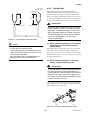
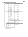
4. WIRING
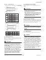
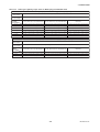
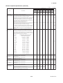
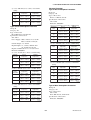
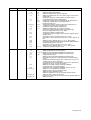
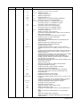
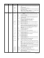
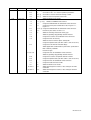
Terminal
Symbols
A
B
C
EX1
EX2
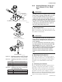
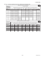
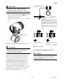
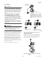
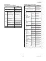
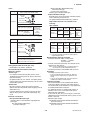
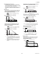
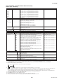
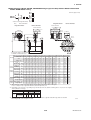
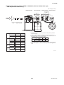
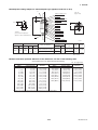
(3) Wiring the Remote Flowtube (GeneralPurpose Use, Submersible Type, Sanitary
Type with Converters
Description
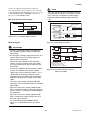
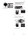
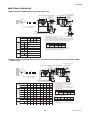
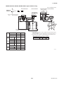
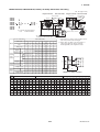
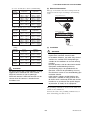
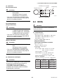
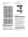
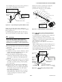
1) Connection with the AXFA11 converter
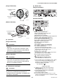
Connect wiring as shown in the figure below.
Flow signal output
Excitation current input
Functional grounding
(Only for explosion proof type)
Protective grounding
(Oitside of the terminal)
I+
I–
CURRENT OUT
SO1+ SO2+ COM
STATUS OUT
N/–
L/+
POWER SUPPLY
EX1
EX2
EXCIT ATION
AL+
AL–
ALARM OUT
C
SA
A
SIGNAL
B
F042401.EPS
SB
AXFA11 converter
FUSE
2.5A 250V
P+
P–
PULSE OUT
SI1+
SI2+
COM
STATUS IN
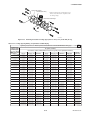
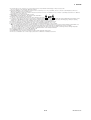
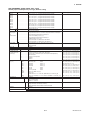
Figure 4.2.10 Terminal Configuration (Explosion proof
Type)
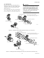
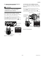
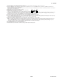
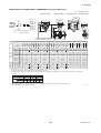
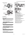
Excitation cable
AXFC dedicated
signal cable
Converter
A
SA
A
B
SB
C
EX1
EX2
EX2
B
EX1
C
Remote
flowtube
Taping*
A
B
Taping*
C
EX1
EX2
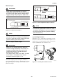
* Individually tape and insulate the
shields corresponding to SA and
SB on the remote flowtube side.
Remote flowtube
F0426.EPS
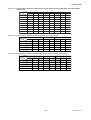
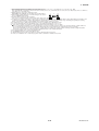
Figure 4.2.11 Wiring Diagram
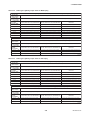
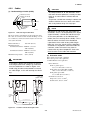
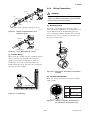
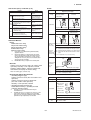
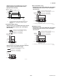
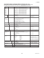
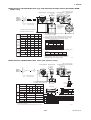
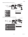
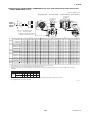
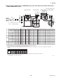
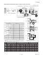
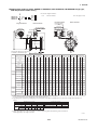
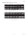
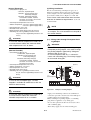
2) Connection with the AXFA14 converter
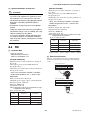
Connect wiring as shown in the figure below.
AXFA14 converter
EX1
EX2
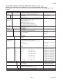
Excitation cable
C
AXFC dedicated
signal cable
SA
A
B
SB
Converter
A
EX2
B
C
EX1
Remote flowtube
SA
A
B
SB
C
EX1
EX2
Remote
flowtube
Taping*
A
B
Taping*
C
EX1
EX2
* Individually tape and insulate the
shields corresponding to SA and
SB on the remote flowtube side.
F0427.EPS
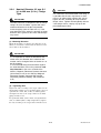
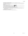
Figure 4.2.12 Wiring Diagram
4-12
IM 01E20D01-01E