1
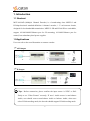
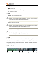
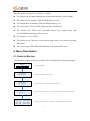
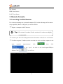
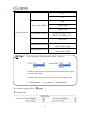
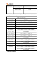
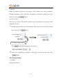
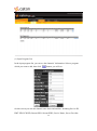
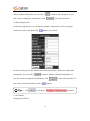
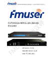
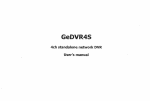
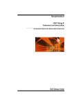
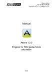
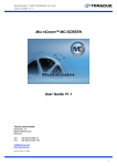
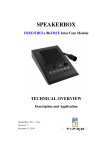
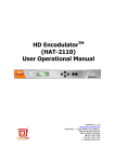
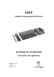
Multichannel MPEG-2& H.264 SD EncoderMCE-6108AD User’s Manual Contents 1. Introduction ................................................................................................................ 2 1.1 Abstract ............................................................................................................. 2 1.2 Applications ...................................................................................................... 2 1.3 Main Features ................................................................................................... 3 1.4 Input and Output Interface ................................................................................ 3 1.5 Front Panel ........................................................................................................ 3 1.6 RearPanel .......................................................................................................... 4 2. Menu Description....................................................................................................... 5 2.1 Power up Booting ............................................................................................. 5 2.2 Menu Definition ............................................................................................... 6 2.2.1 Basic Operations ...................................................................................... 6 2.2.2 Encode Setting ......................................................................................... 7 2.2.3 Output Setting ........................................................................................ 11 2.2.4 System Setting........................................................................................ 13 2.2.5 Input Status ............................................................................................ 14 3. RemoteConsole ........................................................................................................ 15 3.1 Launching the Web Browser .......................................................................... 15 3.2 Status Display ................................................................................................. 17 3.3 Configuration .................................................................................................. 18 3.3.1 Encode .................................................................................................... 18 3.3.2 Output Setting ........................................................................................ 29 3.3.3 Sys Info Setting ...................................................................................... 34 4. Technical Parameters ............................................................................................... 39 4.1 Video Encoding Index .................................................................................... 39 4.2 Audio Encoding Index .................................................................................... 40 4.3 Input and Output Interface .............................................................................. 41 4.4 Physical Characteristics .................................................................................. 42 1. Introduction 1.1 Abstract MCE-6108AD (Multiple Channel Encoder) is a broadcasting class MPEG-2 and H.264professional standard-definition 8-channel encoder; 1 U rack-mount chassis, designed for low-bandwidth transmission, MPEG-2 SD and H.264 SD are switchable, support 10/100/1000M Ethernet port for IP streaming, 10/100M Ethernet port for control, has redundancy dual power supplies. 1.2Applications User can refer to the next illustration to connect encoder. ASI Output IP Output Tips:Before connection, please confirm the input source is NTSC or PAL firstly to set “Video Format” correctly; IF user’s Audio source is non-balance Audio, user should convert non-balance Audio to balance Audio; when user select H.264 encoding mode, the decoder should support H.264 decoding mode. 2 1.3 Main Features MPEG-2 SD and H.264 SD are switchable High quality and low bit rate encoding 1U high density layout Support 10/100/1000M Ethernet port for IP streaming, 10/100M Ethernet port for control Redundancy dual power supplies Network management via web-control GUI Equipment cascade 1.4 Input and Output Interface Interface Input Output CVBS(BNC) SDI(BNC) Balance and unbalance audio ASI DVB-ASI(BNC) TS OVER IP(RJ-45) 1.5 Front Panel Input Status LCD Enter Navigation Wheel Esc UID LED Input status indicators Note: when video input source is normal, indicator lights show in green and flashing, when video input source is abnormal, indicator lights are blind. 3 ▲/▼: Select menu ◄/►: Change value Enter: Go to the sub-menu or confirm settings Esc: Esc to exit or cancel Light POWER: Two power indicator lights Note: Normally power indicator lights show in green, no power supplies or power connection is off function, indicator lights show in red. STATUS: Status indicator light Note: Normally status indicator light shows in green, if channel which is enable output but no input source, the indicator light shows in red. ALARM: Alarm indicator light Note: Normally alarm indicator light shows in green, if control or streaming cat-5 connection failed, alarm indicator light shows in red. UID The function is convenient for user to find out the device when many devices are in cabinet from the back panel. When user click the button, the LED in the bottom left corner of the rear panel will be light (keep 900s), when user clicks the button again, the LED will be turned off. 1.6 Rear Panel 8 1 2 3 4 4 5 6 7 The ports in the rear panel are (from left -to- right): The section one: 8-channel Digital and Analog audio interface (left and right). The section two: 8-channel CVBS and SDI interfaces (5-8). The section three: 8-channel CVBS and SDI interfaces (1-4). The section four: Two ASI OUT (right) and One ASI IN(left). The section five: Dual LAN (10/100M control port (upper level) and 10/100/1000M streaming port (low level)). The section six: AC 85~265V. The section seven: The screw in the bottom right corner is for electricity ground connection. The section eight: UID LED (Unit Indicator) in the bottom left corner. 2. Menu Description 2.1 POWER UP BOOTING Turn on power-supply switch, the encoder LCD will display the following messages: Booting Boot startup interface Premium Series MCE-6108AD Start after completion of the interface Encode Setting Output Setting Click any button, LCD screen display these messages Temper=33°C After 1 minutes, if user don’t have any operation, LCD screen display temperature CH1: CH3: CH5: CH7: OK OK OK OK CH2: CH4: CH6: CH8: ERR LOST ERR LOST After 5 minutes, if user click any button, LCD screen display these messages 5 2.2 Menu Definition 2.2.1 Basic Operations Via menu, you can operate as follows: You can click“▲”,“▼”,“Enter”, “Esc” buttons to browse all menus. Click“▲”button, cursor up, click“▼”button, cursor down, click “Enter” to enter sub-menu, click “Esc” button to return prior menu. Setting parameters, you can operate as follows: Please click “Enter” button to come into editing status, when you modify the item. If you want to modify number, please click“◄”,“►”buttons to move cursor, click“▲”“▼”buttons to increase or decrease the value where cursor indicates. After settings, click “Enter” to confirm it. If only to choose on screen parameters, then you can click “▲”, “▼”, buttons to flip up and down, click“◄”, “►”buttons to select parameters. After settings, click “Enter” to confirm it. Tips: “” (on the left hand side) indicates the level of menu selected. “ ”(on the right hand side) indicates the numerical value parameters can be modified, “ ” will disappear in editable mode, and after the modified parameters were saved, “ ” will appear again. “” (on the right hand side) indicates the on screen option parameters can be changed, after the selected option were saved, “” will disappear. 6 2.2.2 Encode Setting Encode Setting Channel 1 Video Source Channel 2 Video Format Channel 3 Video Encode Mode Channel 4 Rate Ctrl Mode < Video Source CVBS > < Video Format PAL > Video Encode Mode < H.264 > < Rate Ctrl Mode CBR > Channel 5 CappedVBR TargetQP CapVBR TargetQP N/A Channel 6 Target Bitrate Target Bitrate 04000 kbps Channel 7 VBR Max Bitrate VBR Max Bitrate N/A VBR Min Bitrate VBR Min Bitrate N/A Audio Encode Mode Audio Encode Mode < MPEG1 Mono > Audio Sample Rate Audio Sample Rate < 32KHz > Channel 8 Audio Bitrate Apply Settings < Audio Bitrate 32kbps > Apply Settings [ _ ]Yes | [ _ ]No The video source setting, user can select video input Video Source source. (Channel---Video Source---Video Source. Click "◄","►" button to select parameters, click "Enter" to confirm it, click "▼" button to next menu, click "Esc" button to return prior menu) The video format setting, user can select video format: Video Format 576i (PAL) or 480i (NTSC). 7 (Channel---Video Format---Video Format. Click "◄","►" button to select parameters, click "Enter" to confirm it, click "▼" button to next menu, click "Esc" button to return prior menu) The video encode mode setting, user can select Video Encode MPEG-2 or H.264 encoding mode. (Channel---Video Encode Mode---Video Encode Mode. Click "◄","►" button to select parameters, click "Enter" to confirm it, click "▼" button to next menu, click "Esc" button to return prior menu) Note: when users select H.264 encoding mode, the decoder should support H.264 decoding mode. The rate ctrl mode setting, user can select: CBR, Rate Ctrl Mode Capped VBR, Target VBR. (Channel--- Rate Ctrl Mode--- Rate Ctrl Mode. Click "◄","►" button to select parameters, click "Enter" to confirm it, click "▼" button to next menu, click "Esc" button to return prior menu) The Capped VBR TargetQP setting, if user Capped VBR TargetQP choose CBR for rate ctrl mode, then capped VBR TargetQP is N/A. Others is effective. (Channel---Capped VBR TargetQP ---Cap VBR TargetQP. Click "◄","►" button to select parameters, click "Enter" to confirm it, click "▼" button to next menu, click "Esc" button to return prior menu) Tips: Target Bitrate The minimal bitrate can be set is 100kbps, the maximal bitrate can be set is 10,000 kbps. (Channel---Target Bitrate--- Target Bitrate. Click"◄","►"buttons to move 8 cursor, click"▲","▼"buttons to modify the value where cursor indicates, select the proper number, click "Enter" to confirm it, click "▼" button to next menu, click "Esc" button to return prior menu) The VBR Max Bitrate setting, if user choose VBR Max Bitrate CBR for rate ctrl mode, then VBR Max Bitrate is N/A. others is effective. (Channel--- VBR Max Bitrate --- VBR Max Bitrate. Click "◄","►" button to select parameters, click "Enter" to confirm it, click "▼" button to next menu, click "Esc" button to return prior menu) Tips: MPEG-2 range is 500K-7000K, H.264 range is 250K-7000K. The VBR Min Bitrate setting, if user choose CBR VBR Min Bitrate for rate ctrl mode, then VBR Min Bitrate is N/A. others is effective. (Channel--- VBR Min Bitrate --- VBR Min Bitrate. Click "◄","►" button to select parameters, click "Enter" to confirm it, click "▼" button to next menu, click "Esc" button to return prior menu) Tips: MPEG-2 range is500K-7000K, H.264 range is250K-7000K. The audio encode mode setting, user can select one Audio Encode Mode of audio formats: MPEG1 Mono, MPEG1 Stereo, AAC-LC Mono, AAC-LC dual Mono, AAC-LC Stereo, AAC-HE v1 Mono, AAC-HE v1 dual Mono, AAC-HE v1 Stereo, AAC-HE v2 Stereo, MPEG-1 Pass, AAC-LC Pass, HE-AAC Pass, AC3-CE Pass, AC3-PE Pass. (Channel---Audio Encode Mode---Audio Encode Mode. Click "◄","►" 9 buttons to select one of on screen parameters, click "Enter" to confirm it, click "▼" button to next menu, click "Esc" button to return prior menu) The audio sample rate setting, user can select one of Audio Sample Rate audio sample rates: 32KHz, 44.1KHz,48KHz. (Channel ---Audio Sample Rate---Audio Sample Rate. Click "◄","►" buttons to select parameters, click "Enter" to confirm it, click "▼" button to next menu, click "Esc" button to return prior menu) The audio bitrate setting, user can select one of audio Audio Bitrate bitrates: 32 kbps, 48 kbps,56kbps, 64 kbps, 80 kbps, 96 kbps, 112 kbps, 128 kbps, 160 kbps, 192 kbps, 224 kbps, 256 kbps, 320 kbps, and 384 kbps, 448 kbps, 512 kbps, 576 kbps, 640 kbps. (Channel --- Audio Bitrate --- Audio Bitrate. Click "◄","►"button to select parameters, click "Enter" to confirm it, click "▼" button to next menu, click "Esc" button to return prior menu) Note: The range of audio bitrate depends on different audio formats. Apply new setting parameters. Apply Settings (Channel ---Apply Settings---Apply Settings. Click "◄","►"button to move cursor to choose “Yes” or “No”, select “Yes”, then click "Enter", new setting parameters will be saved and applied, click "Esc" button to cancel settings and go back to prior menu) Note: 1. Settings will take effect only after above parameters was confirmed through "Apply Settings". 2. Settings will cause the short pause of the current encoding stream. 10 2.2.3 Output Setting Output Setting IP Output Setting Channel 1 [ON] IP Addr Setting IP Address 224.001.001.001 Channel 2 [ON] IP Port Setting IP Port 06000 Channel 3 [OFF] Protocol Setting < Protocol UDP > Channel 4 [OFF] Channel 5 [ON] Channel 6 [ON] Channel 7 [OFF] Channel 8 [OFF] ASI Output Setting MUX Bitrate Channel 1 [ON] MUX Bitrate 20808[>09748]kbps CH1 TS Bitrate 06000 kbps Channel 2 [ON] CH2 TS Bitrate 06000 kbps Channel 3 [OFF] CH3 TS Bitrate 06000kbps Channel 4 [OFF] CH4 TS Bitrate 06000 kbps Channel 5 [ON] CH5 TS Bitrate 06000 kbps Channel 6 [ON] CH6 TS Bitrate 06000 kbps Channel 7 [OFF] CH7 TS Bitrate 06000kbps Channel 8 [OFF] CH8 TS Bitrate 06000 kbps 8-channel IP output can be open or closed. IP Output Setting (IP Output Setting--- Channel. click"◄","►"button to move cursor to choose “OFF” or “ON”, click "Enter" to confirm it, click "Esc" button to return prior menu) 11 The multicast or unicast address setting. IPAddr Setting (Channel 1--- IPAddr Setting---IP Address. Click"◄","►" buttons to move cursor, click "▲","▼"buttons to modify the number where cursor indicates, select the proper number, click "Enter" to confirm it, click "▼" button to next menu, click "Esc" button to return prior menu) Note: Multicast address range:224.0.0.1——239.255.255.254 The destination port setting. IP Port Setting (Channel 1---IP Port Setting--- IP Port. Click"◄","►"buttons to move cursor, click"▲","▼"buttons to modify the number where cursor indicates, select the proper number, click "Enter" to confirm it, click "▼" button to next menu, click "Esc" button to return prior menu) The protocol setting. Protocol (Channel 1---Protocol Setting--- Protocol. Click"◄","►"button to select parameters, click "Enter" to confirm it, click "Esc" button to return prior menu) Tips: user can look over IP bitrate via web. 8-channel ASI output can be open or closed. ASI Output Setting (ASI Output Setting--- Channel. click "◄","►"button to move cursor to select “OFF’ or “ON”, click "Enter" to confirm it, click "Esc" button to return prior menu) 12 The total bitrate of multiplexed output stream setting. MUX Bitrate (ASI Output Setting---MUX Bitrate--- MUX Bitrate. Click"◄","►"button to move cursor, click"▲","▼"buttons to modify the value where cursor indicates, set the proper bit rate, click "Enter" to confirm it, click "▼" button to next menu, click "Esc" button to return prior menu) Note: The value of Mux bitrate should be big than the value of TS bitrate for the channels which are in working status. Channel Each channel ASI out setting, user can open or close different channel. Channel is open that can browse TS Bitrate. 2.2.4 System Setting System Setting System Info Stream Parameter IP 202.000.000.160 Stream IP Setting IP Address IP Address 202.000.000.160 Subnet Mask Subnet Mask 255.255.255.000 Gateway Gateway 202.000.000.001 IP Address IP Address 202.000.000.159 Subnet Mask Subnet Mask 255.255.255.000 Gateway Gateway 202.000.000.001 Recall 00 Default 01 ------ Factory Factory Setting [ _ ]Yes |[ _ ]NO Control IP Setting Profile Reboot Device [ _ ]Yes|[ _ ]NO Reboot Device 13 System setting includes System Info, Stream IP, System Setting Control IP, Profile, Reboot Device settings. Including Stream IP, Stream MAC, Control IP, System Info Control MAC, Hardware Version, Firmware Version, Software Version, Model Number, Serial Number. Stream IP Setting Control IP Setting Stream IP Setting. Control IP Setting. Gate way must be set. Loading default parameters, user can get the default Recall parameters and take them in effect. There store initial setting, IP and Encode all settings Factory are restored (Select Yes or No, click “Enter” to restore initial setting). Reboot Device Reset all configuration parameters, the data which have not been saved may be lost. (Reboot Device---Reboot Device. Click "◄","►"button to move cursor to select “Yes” or “No”. After modification, click "Enter" to confirm it, click "Esc" button to return prior menu) (Reboot Device--- Reboot Device. Click "◄","►"button to move cursor to select “Yes” or “No”. After modification, click "Enter" to confirm it, click "Esc" button to return prior menu) 2.2.5 Input Status Input Status: Show input sync status. Input Status CH1: CH3: CH5: CH7: 14 OK OK OK OK CH2: CH4: CH6: CH8: ERR LOST ERR LOST OK: Normal. ERR: Error Source. LOST: Lost Source. 3. Remote Console 3.1Launching the Web Browser Use a browser running one a personal computer (PC) to take advantage of the remote setup capability. Below is the guide you need to follow: Prepare a computer with IE browser. Tips: IE version 8.0 or above Firefox version 6.0.2 or above are highly recommended. Connect your PC to the management network interface of the device via Ethernet Confirm computer IP address, make sure that the device and the computer in the same network segment(steps: click ,then click , In the ‘’open’’ the back of the blank input CMD, as follows Click ), you will see: 15 Input ipconfig, click enter, you will see: Tips: is the computer IP address. Confirm the device IP address via front panel(steps: System Setting --- System Info--- Control Parameter--- IP Address). Note: 1.If the device and computer IP address in the different network segment, please modify the device IP address, and ensure that the IP address was not occupied in the network for avoiding address conflict. 2. Make sure that the Control and Stream IP address is not same. Input the device IP address in the web, click enter, you will see: Input default user name and password, all are “admin”. 16 3.2 Status Display When you get a successful user authentication at the MCE-6108AD login prompt, the device status display screen appears as shown below. The device status display screen shows the status of the configuration of the device in which it comes up with this screen. Device status display area The status display area shows the following topics of information: -Encode ······Indicates the encoder status, correct configuration displays ACTIVE, wrong configuration displays ERROR! if configuration is not done is displays Init... -Video Input······PAL/NTSC is normal status; Sync Lost is no video input status, INVALID is wrong status. -Temperature ······Displays the internal temperature(℃)status of the device. -Power1 ······ Displays power1connection condition. -Power2 ······Displays power2 connection condition. 17 3.3 Configuration 3.3.1 Encode 1. Channel Setting Web page as follows: TS Bitrate: Channel total TS bitrate. Video Parameters (1) Video Parameters: Menu Name Range 18 CVBS Source SDI H.264 Encode Mode MPEG-2 NONE 704*576 640*576 544*576 528*576 480*576 Rescale Resolution 352*576 352*288 Video Parameters 352*240 320*240 320*180 176*144 160*120 160*90 PAL Format NTSC 4×3 Aspect Ratio 16×9 19 2.35×1 1×1 CBR Rate Control Mode Capped VBR Target VBR Video Parameters Capped VBR TargetQP H.264 encoding: 2 to 63 MPEG-2 encoding: 2 to 31 Target Bitrate (kbps) 100-10,000 VBR Max Bitrate (kbps) MPEG-2: 500K-7000K H.264: 250K-7000K VBR Min Bitrate (kbps) MPEG-2: 500K-7000K H.264: 250K-7000K Tips:1. Select parameters through dropdown menu, as follows: 2. When user selects H.264 encoding mode, the decoder should support H.264 decoding mode. 3. Settings will cause the short pause of the current encoding stream. 4.VBRMinBitrate < = Target Bitrate < = VBRMaxBitrate (2) Advanced setting (Click ): H.264setting 20 Menu Name Range Disabled Reference B-Frames Enabled Disabled CABAC Enabled Disabled H.264 Setting 8×8 Transform Enabled OFF Loop Filter Mode ON Not across slice bounda MPEG-2 Setting Menu Name Range 8 Bits 9 Bits Intra-DC Precision 10 Bits MPEG-2 Setting 11 Bits Alternate VLC Intra-VLC Format MPEG-1 VLC Q Scale Type Non-Linear 21 Linear Disabled Alternate Scan Enabled Common Setting Menu Name Range Main Profile Profile High Profile MPEG-2 Automatic, High, Main Level Automatic,1.0,1.1,1.2,1.3,2.0,2.1,2.2, H.264 3.0,3.1,3.2,4.0,4.1,4.2,5.0,5.1 Slice Size 1~80 GOP Size 1~255 No IDRS Every 1-Frame IDR Frequency Every second 1-Frame Every third1-Frame Automatic Coding Mode Frame 22 MBAFF PAFF Disable Dynamic GOP Mode Enable Open GOP GOP Closed GOP Automatic IP IPB IPBB GOP Structure IPBBB IPBBBB IPBBBBB IPBBBBBB IPBBBBBBB Automatic IP IPB IPBB Dynamic GOP Maximum IPBBB IPBBBB IPBBBBB IPBBBBBB 23 IPBBBBBBB Automatic IP IPB IPBB Dynamic GOP Minimum IPBBB IPBBBB IPBBBBB IPBBBBBB IPBBBBBBB Video Pre-Process Setting Menu Name Range Disabled Invert Field Order Enabled Horizontal Blur Pre Filtering None Disabled Fade Detection Enabled 24 Disabled Scene Change Detection Enable Enabled Pre-Deblocking Strength 0~3 MCTF Strength 0~7 Disabled Skin Tone Detection Enabled 0~7 Skin Tone Detection Strength 0~6 Skin Tone Detection Delta-QP Max Audio Parameters Menu Name Range SDI-CH1/2 SDI-CH3/4 SDI-CH5/6 Source SDI-CH7/8 Audio Parameters AES-EBU ANALOG 32KHZ 25 Sampling Rate 44.1KHZ 48KHZ MPEG1 Mono MPEG1 Stereo AAC-LC Mono AAC-LC dual Mono AAC-LC Stereo AAC-HE v1 Mono Audio Parameters AAC-HE v1 dual Mono Encode Mode AAC-HE v1 Stereo AAC-HE v2 Stereo MPEG-1 Pass AAC-LC Pass HE-AAC Pass AC3-CE Pass AC3-PE Pass Mute Volume Normal 26 Bitrate (Kbps) 32~640 Delay(0~1000ms) 0~1000 Gain(dB) -20~20 The range of audio bitrate depends on different audio format. Please refer below form: Range of bit rate setting Audio Format Bitrate(Kbps) MPEG1 Mono 32,48,56,64,80,96,112,128,160,192 MPEG1 Stereo 64, 96, 112,128,160,192,224,256,320,384 AAC-LC Mono 32,48,56,64,80,96,112,128,160,192 AAC-LC dual Mono 32,48,56,64,80,96,112,128,160,192,224,256,320,384 AAC-LC Stereo 32,48,56,64,80,96,112,128,160,192,224,256,320,384 AAC-HE v1 Mono 32,48,56,64,80,96 AAC-HE v1 dual Mono 32,48,56,64,80,96,112,128,160,192 AAC-HE v1 Stereo 32,48,56,64,80,96,112,128,160,192 AAC-HE v2 Stereo 32,48,56,64,80,96 MPEG-1 Pass 32,48,56,64,80,96,112,128,160,192,224,256,320,384, 448,512,576,640 AAC-LC Pass 32,48,56,64,80,96,112,128,160,192,224,256,320,384, 448,512,576,640 HE-AAC Pass 32,48,56,64,80,96,112,128,160,192,224,256,320,384, 448,512,576,640 AC3-CE Pass 32,48,56,64,80,96,112,128,160,192,224,256,320,384, 448,512,576,640 AC3-PE Pass 32,48,56,64,80,96,112,128,160,192,224,256,320,384, 448,512,576,640 Program Information 27 This option edits Transport PID and other relevant parameters, system generates the default PID automatically, and user can edit it. Note: 1. Avoid channel PID conflict. 2. Avoid channel PID conflict which enabled in ASI output. Tips: Click , it will appear information, it indicates configuration complete. 2. Preset Setting The screen shown as follows, which allows you to recall, save, download and upload a preset parameter. 28 (1) Recall Recall a parameter preserved in the device, and it reflects it in active parameter. Through dropdown menu select the configuration parameters which have been preserved, then click button. (2) Save or delete This item is to preserve the current parameter as preset parameter; it can preserve ten parameters at most. Through dropdown menu select preset number, then input preset name what you wished in the form, then click button. For example: Input para_1 Click Select button and refresh page, you will see: the configuration parameters which have been preserved, then click button. 3.3.2 Output Setting 1. Multiplex Web page as follows: 29 (1) Input Program List In the input program list, you can see the channels’ information. Select a program which you want to add, then click button, you will see: On this screen you can edit channel some basic information. Including Service ID, PMT PID, PCR PID, Stream PID1, Stream PID2, Service Name, Server Provider. 30 When confirm information, you can click button to add a program. If you don’t want to change the information, click to cancel the operation. (2) Mux Program List In the mux program list, you can edit the channels’ information. Select a program which you want to edit, then click button, you will see: On this screen you can edit channel some basic information. When you confirm the information, you can click button to change a program information. If you don’t want to change the information, click you want to delete this channel, click Tips: 1. Click to cancel the operation. If button. , it will appear 2. ASI Output Web page as follows: 31 information. Multiplexed output parameters setting -Transport ID ······Set Transport ID, the range of data is 1~65535. -Mux Bitrate······Set 8-channel multiplexed bitrate -External ······Used for equipment cascade Channel parameters setting -Output Enable······Set effectiveness or ineffectiveness of ASI Output -TS Bitrate ······Show the TS bitrate -VideoBitrate······Show the video bitrate -Audio Bitrate······Show the audio bitrate -IP Bitrate······Show the IP bitrate Interval setting -PAT Interval (ms) ······Set PAT table send interval for Multiplexed output -SDT Interval (ms) ······Set SDT table send interval Multiplexed output -PMT Interval (ms) ······Set PMT table send interval Multiplexed output 32 should Note: The value of MUX Bitrate be big than the value ofthe total TS bitrate which enable for output, as follows: Tips: 1. Click , it will appear information, it indicates ASI output complete. 3. IP Output Web page as follows: CH 1 (2 ,3,4,5,6,7,8) Setting -Enable -Target IP ······Set effectiveness or ineffectiveness of IP Output ······Set Target IP -TTL ······Set TTL 33 -Protocol ······Set Protocol (UDP/RTP) -Target Port ······Set Target Port Multilplex Setting -Enable ······Set effectiveness or ineffectiveness of IP Output -Target IP ······Set Target IP -TTL ······Set TTL -Protocol ······Set Protocol (UDP/RTP) -Target Port ······Set Target Port Note:User can set target IP as unicast/multicast (default value is 224.1.1.1, multicast address range:224.0.0.1—239.255.255.254), After settings, and tick Enable which channel you want to choose, as follows: . For multilplex streaming output, you must config the asi output first. Tips: 1.Click button, it will appear information, it indicates IP Output complete. 2. User can see the IP output bitrate through the web page “ASI Output”, please refer the page 32. 3.3.3 Sys Info Setting 1. System Info User can inquire device model, serial number, encode board hardware version, encode board software version, encode board firmware version, I/O board hardware version, I/O board firmware version. Web page as follows: 34 2. Network Web page as follows: -IP address······Set IP address -Subnet Mask ······Set Subnet Mask 35 -Gateway ······Set Gateway -MAC Address ······User can browse MAC Address -Link status ······Look over the device link status With 1000M switch, normally link status display: 100 Mbps (Control port),1000 Mbps (Stream port), and otherwise display With 100M switch, normally link status display: 100 Mbps (Control port),100 Mbps (Stream port), and otherwise display Tips:click ,a dialog window will appear to remind of user whether modify or not, as follows: 3. Load Default Web page as follows: 36 Tips:When you press button, dialog window will appear to remind of user whether reset or not, as follows: Load Default parameters: Video Encode Mode H.264 Format PAL Rate Control Mode CBR Target Bitrate(Kbps) 4000 Audio Encode Mode MPEG1 Stereo Sampling Rate(KHz) 48 Bitrate(Kbps) 192 4. Reboot Web page as follows: This menu function is to restart the equipment, click to reboot the device. 37 to required to be able 5. SW Upgrade Web page as follows: This menu function is to upgrade software version, click upgrade file, select it and click . 38 to find the Tips:1.When you click button, dialog window will appear to remind of you whether upgrade or not, as follows: 2.Upgrade is complete when information appears. Warming: Don’t turn off the power when software updates. 6. Password Web page as follows: 39 This menu function is to modify the device password -Login ID······Enter user’s name -New Password······Enter new password -Password Again ······Re-enter new password ······Show the contents of the password, enter the new password - twice to confirm whether the same. Tips:1. New Password and Password Again: 0~9, a~z ,A~Z 2. When you click button, a dialog window will appear to remind of you whether modify or not, as follows: 4. Technical Parameters 4.1 Video Encoding Index Video Encode Index Chroma format 4:2:0 H.264 Profile Main 40 High Bitrate 250kbps~7Mbps Format 576i(25):720×576(PAL) 480i(29.97): 720×480(NTSC) MPEG-2 Profile Main High Bitrate 500kbps~7Mbps 576i(25):720×576(PAL) Format 480i(29.97): 720×480(NTSC) 4.2 Audio Encoding Index Audio Encode Index Input Signal Type SDI embedded audio ,AES/EBU and Analog Audio MPEG1 Mono MPEG1 Stereo AAC-LC Mono AAC-LC dual Mono Audio Format AAC-LC Stereo AAC-HE v1 Mono AAC-HE v1 dual Mono 41 AAC-HE v1 Mono AAC-HE v2 Stereo MPEG-1 Pass Audio Format AAC-LC Pass HE-AAC Pass AC3-CE Pass AC3-PE Pass 32kHz Sampling Rate 44.1kHz 48kHz 4.3 Input and Output Interface Video Input Interface Type and Number 8×SDI / 8×CVBS Format PAL BNC Interface 75 Ohm NTSC BNC Interface 75 Ohm Audio Input Audio 8×AES/EBU/8×Analog Stereo Audio 8×SDI embedded audio TS Input Interface ASI×1; BNC impedance75Ohm 42 TS Output Interface ASI×2; BNC impedance75Ohm Max Output Rate 212Mbps MPEG-TS StreamIP Output UDP/RTP unicast /multicast TS OVER IP Max Output Rate 400Mbps 4.4 Physical Characteristics Power Indicator Power Number ×2 Voltage AC85~265V Frequency 50/60Hz Typical Power Consumption ≤40W Operating Environment Working Temperature 0~55°C Storing Temperature -10~70°C 43 Humidity <90%(non-condensing) Physical Index 19”×1.75”×24”(1RU) Dimension 48.26cm×4.45cm×60.69cm 24Ibs Weight 5Kg 44