1
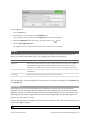
USER MANUAL
Gocator 2300 & 2880 Series
Document revision: D
Copyright
Copyright © 2015 by LMI Technologies, Inc. All rights reserved.
Proprietary
This document, submitted in confidence, contains proprietary information which shall not be
reproduced or transferred to other documents or disclosed to others or used for manufacturing or any
other purpose without prior written permission of LMI Technologies Inc.
No part of this publication may be copied, photocopied, reproduced, transmitted, transcribed, or
reduced to any electronic medium or machine readable form without prior written consent of LMI
Technologies, Inc.
Trademarks and Restrictions
Gocator™ is a registered trademark of LMI Technologies, Inc. Any other company or product names
mentioned herein may be trademarks of their respective owners.
Information contained within this manual is subject to change.
This product is designated for use solely as a component and as such it does not comply with the
standards relating to laser products specified in U.S. FDA CFR Title 21 Part 1040.
Contact Information
For more information, please contact LMI Technologies.
LMI Technologies, Inc. 1673 Cliveden Ave.
Delta, BC V3M 6V5
Canada
Telephone: +1 604 636 1011
Facsimile: +1 604 516 8368
www.lmi3D.com
Gocator 2300 & 2880 Series
2
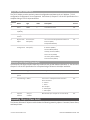
Table of Contents
Resolution and Accuracy
Copyright
2
Table of Contents
3
Introduction
9
Safety and Maintenance
Laser Safety
10
10
38
X Resolution
38
Z Resolution
38
Z Linearity
39
Profile Output
Coordinate Systems
40
40
Sensor Coordinates
40
System Coordinates
40
Laser Classes
11
Precautions and Responsibilities
11
Class 3B Responsibilities
12
Nominal Ocular Hazard Distance (NOHD)
13
User Interface Overview
42
Systems Sold or Used in the USA
14
Common Elements
43
Resampled and Uniform Spacing Profile
Format
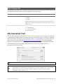
Gocator Web Interface
41
42
Electrical Safety
14
Environment and Lighting
15
Saving and Loading Settings
43
Sensor Maintenance
16
Managing Multiple Settings
44
17
Recording, Playback, and Measurement
Simulation
45
Downloading, Exporting, and Uploading
Recorded Data
46
Getting Started
System Overview
17
Standalone System
17
Dual-Sensor System
17
Multi-Sensor System
Hardware Overview
18
20
Gocator 2300 & 2880 Sensor
20
Gocator 2300 & 2880 Cordsets
20
Master 100
21
Master 400/800
22
Master 1200/2400
22
Calibration Targets
23
Installation
Grounding - Gocator
Mounting
26
Orientations
27
Network Setup
30
Client Setup
30
Gocator Setup
32
Running a Standalone Sensor System
32
Running a Dual-Sensor System
33
Next Steps
Theory of Operation
3D Acquisition
Principle of 3D Acquisition
Gocator 2300 & 2880 Series
48
Metrics Area
48
Data Viewer
49
System Management and Maintenance
36
37
37
37
50
Manage Page Overview
50
Sensor System
51
Sensor Autostart
51
Dual-Sensor System Layout
51
25
26
43
Log
25
Recommended Grounding Practices - Cordsets 25
Grounding - Master 400/800/1200/2400
Toolbar
Buddy Assignment
53
Exposure Multiplexing
54
Networking
54
Motion and Alignment
55
Alignment Reference
56
Encoder Resolution
56
Encoder Value and Frequency
Travel Speed
57
57
Jobs
57
Security
59
Maintenance
60
Sensor Backups and Factory Reset
61
Firmware Upgrade
62
Scan Setup and Alignment
Scan Page Overview
64
64
3
Scan Modes
65
Measure Page Overview
109
Triggers
66
Data Viewer
110
Trigger Examples
68
Tools Panel
110
Trigger Settings
69
Measurement Tool Management
110
71
Adding and Removing Tools
110
71
Enabling and Disabling Measurements
111
Tracking Window
72
Editing a Tool or Measurement Name
113
Transformations
74
Changing a Measurement ID
113
Sensor
Active Area
Exposure
74
Common Measurement Settings
114
Single Exposure
75
Source
114
Dynamic Exposure
76
Regions
114
Multiple Exposure
77
Decisions
115
Spacing
79
Filters
117
Sub-Sampling
79
Measurement Anchoring
118
Spacing Interval
80
Profile Measurement
119
Material
81
Feature Points
120
Alignment
83
Fit Lines
121
Alignment States
83
Measurement Tools
122
Alignment Types
84
Alignment: With and Without Encoder
Calibration
84
Aligning Sensors
84
Clearing Alignment
Area
122
Circle
124
Dimension
125
Groove
127
87
Intersect
130
88
Line
131
Gap Filling
88
Position
133
Median
89
Panel
134
Smoothing
90
Gap
134
Decimation
91
Flush
135
Filters
Surface Generation
91
Part Detection
93
Tilt
141
96
Script
141
Edge Filtering
Data Viewer
Strip
137
97
Surface Measurement
142
Data Viewer Controls
98
Measurement Tools
143
Video Mode
98
Bounding Box
143
98
Exposure View
Countersunk Hole
146
100
Ellipse
151
Profile Mode
101
Hole
153
Surface Mode
103
Spots and Dropouts
Height Map Color Scale
105
Measurement Region
Opening
157
158
Region Definition
106
Intensity Output
107
Plane
164
109
Position
166
Measurement
Gocator 2300 & 2880 Series
Measurement Region
164
4
Stud
Measurement Region
168
171
Volume
171
Script
173
EdgeFiltering
Triggers
Tools
203
203
204
Profile Types
204
Script Measurement
174
ProfileRegion2D
204
Built-in Functions
174
ProfileFeature
205
179
ProfileLine
205
Output Page Overview
179
Surface Types
205
Ethernet Output
180
Region3D
205
Digital Output
183
SurfaceRegion2D
206
Analog Output
186
SurfaceFeature
206
Serial Output
188
ProfileArea
206
Output
Dashboard
190
ProfileCircle
208
Dashboard Page Overview
190
ProfileDimension
208
System Panel
190
ProfileGroove
210
Measurements
191
ProfileIntersect
211
Gocator Device Files
193
ProfileLine
212
193
ProfilePanel
213
193
ProfilePosition
215
193
ProfileStrip
216
Job Files
Configuration (Root)
Setup
Filters
194
Script
218
XSmoothing
194
SurfaceBoundingBox
218
YSmoothing
195
SurfaceEllipse
219
XGapFilling
195
SurfaceHole
220
YGapFilling
195
SurfaceCsHole
222
XMedian
195
SurfaceOpening
224
YMedian
195
SurfacePlane
226
XDecimation
196
SurfacePosition
227
YDecimation
196
SurfaceStud
227
Layout
196
SurfaceVolume
229
Alignment
197
SurfaceCsHole
230
Disk
197
Bar
197
Plate
198
ASCII
234
198
EIP
234
Tracking
199
Modbus
235
Material
Devices / Device
Output
Ethernet
232
232
199
Digital0 and Digital1
235
SurfaceGeneration
201
Analog
235
FixedLength
201
Serial
236
VariableLength
202
Rotational
202
PartDetection
202
Gocator 2300 & 2880 Series
Selcom
237
ASCII
237
Transformation File
238
5
Transform
Device
Protocols
Gocator Protocol
General
239
Schedule Digital Output
257
239
Schedule Analog Output
257
240
Ping
258
240
Reset
258
240
Backup
259
Modes
240
Restore
259
Buddy Communication Channels
240
Restore Factory
260
States
241
Set Recording Enabled
260
Data Types
241
Get Recording Enabled
261
Status Codes
242
Clear Replay Data
261
242
Set Playback Source
261
Get Address
242
Get Playback Source
262
Set Address
243
Simulate
262
244
Seek Playback
263
Protocol Version
244
Step Playback
263
Get Address
245
Playback Position
264
Set Address
245
Clear Measurement Stats
264
Get System Info
246
Simulate Unaligned
264
Get States
247
Acquire
265
Log In/Out
248
Acquire Unaligned
265
Change Password
248
Read File (Progressive)
265
Set Buddy
249
Export CSV (Progressive)
266
List Files
249
Export Bitmap (Progressive)
266
Copy File
250
Read File
250
Get Protocol Version
267
Write File
250
Start Upgrade
268
Delete File
251
Get Upgrade Status
268
Get Default Job
251
Get Upgrade Log
268
Set Default Job
252
Data Results
269
Get Loaded Job
252
Stamp
269
Set Alignment Reference
252
Video
270
Get Alignment Reference
253
Profile
271
Clear Alignment
253
Resampled Profile
272
Get Timestamp
253
Profile Intensity
272
Get Encoder
254
Surface
273
Reset Encoder
254
Surface Intensity
273
Start
254
Measurement
274
Scheduled Start
255
Alignment Result
275
Stop
255
Exposure Calibration Result
275
Start Alignment
256
Health Results
275
Start Exposure Auto-set
256
Modbus TCP Protocol
280
Software Trigger
256
Discovery Commands
Control Commands
Gocator 2300 & 2880 Series
Upgrade Commands
Concepts
267
280
6
Messages
280
Examples
302
Registers
281
Sample Project Environment Variable
303
Control Registers
282
Header Files
303
Output Registers
283
Class Hierarchy
303
State
283
GoSystem
303
Stamp
283
GoSensor
304
Measurement Registers
284
GoSetup
304
286
GoLayout
304
Concepts
286
GoTools
304
Basic Object
286
GoTransform
304
Identity Object (Class 0x01)
286
GoOutput
304
TCP/IP Object (Class 0xF5)
287
Ethernet Link Object (Class 0xF6)
287
Value Types
304
287
Output Types
305
Command Assembly
288
GoDataSet Type
305
Sensor State Assembly
288
Measurement Values and Decisions
306
Sample State Assembly
289
EtherNet/IP Protocol
Assembly Object (Class 0x04)
ASCII Protocol
Data Types
Operation Workflow
304
306
292
Initialize GoSdk API Object
307
292
Discover Sensors
308
Asynchronous and Polling Operation
292
Connect Sensors
308
Command and Reply Format
292
Configure Sensors
308
Special Characters
293
Enable Data Channels
308
Standard Result Format
293
Perform Operations
308
Custom Result Format
294
Ethernet Communication
Control Commands
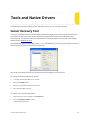
Limiting Flash Memory Write Operations
310
294
Tools and Native Drivers
311
Start
295
Sensor Recovery Tool
311
Stop
295
GenTL Driver
313
Trigger
295
16-bit RGB Image
314
Load Job
296
16-bit Grey Scale Image
315
Stamp
296
Registers
316
Stationary Alignment
297
XML Settings File
318
Moving Alignment
297
Clear Alignment
CSV Converter Tool
318
298
Troubleshooting
320
Data Commands
298
Specifications
322
Get Result
298
Gocator 2300 Series
323
Get Value
299
Gocator 2320
324
Get Decision
300
Gocator 2330
326
Health Commands
300
Gocator 2340
327
Get Health
300
Gocator 2350
328
Software Development Kit
302
Gocator 2370
330
Setup and Locations
302
Gocator 2375
333
Class Reference
302
Gocator 2380
335
Gocator 2300 & 2880 Series
7
Gocator 2880 Sensor
Gocator 2880
Gocator Power/LAN Connector
338
339
342
Grounding Shield
342
Power
343
Laser Safety Input
343
Gocator 2300 & 2880 I/O Connector
344
Grounding Shield
344
Digital Outputs
345
Inverting Outputs
345
Digital Inputs
345
Encoder Input
346
Serial Output
347
Analog Output
347
Master 100
Master 100 Dimensions
Master 400/800
349
350
351
Master 400/800 Electrical Specifications
352
Master 400/800 Dimensions
353
Master 1200/2400
354
Master 1200/2400 Electrical Specifications
355
Master 1200/2400 Dimensions
356
Parts and Accessories
357
Return Policy
359
Software Licenses
360
Support
366
Contact
367
Gocator 2300 & 2880 Series
8
Introduction
The Gocator 2300 series of laser profiling sensors is designed for 3D measurement and control
applications. Gocator sensors are configured using a web browser and can be connected to a variety of
input and output devices.
This documentation describes how to connect, configure, and use a Gocator. It also contains reference
information on the device's protocols and job files.
Notational Conventions
This guide uses the following notational conventions:
Follow these safety guidelines to avoid potential injury or property damage.
Consider this information in order to make best use of the product.
Gocator 2300 & 2880 Series
9
Safety and Maintenance
The following sections describe the safe use and maintenance of Gocator sensors.
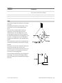
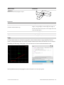
Laser Safety
Gocator sensors contain
semiconductor lasers that emit visible
or invisible light and are designated as
Class 2M, Class 3R, or Class 3B,
depending on the chosen laser option.
Gocator sensors are referred to as
components, indicating that they are
sold only to qualified customers for
incorporation into their own
equipment. These sensors do not
incorporate safety items that the
customer may be required to provide
in their own equipment (e.g., remote
interlocks, key control; refer to
references for detailed information).
As such, these sensors do not fully
comply with the standards relating to
laser products specified in IEC 60825-1
and FDA CFR Title 21 Part 1040.
Use of controls or adjustments or performance of procedures other than those specified herein
may result in hazardous radiation exposure.
References
1. International standard IEC 60825-1 (2001-08) consolidated edition, Safety of laser products – Part 1:
Equipment classification, requirements and user's guide.
2. Technical report 60825-10, Safety of laser products – Part 10. Application guidelines and explanatory
notes to IEC 60825-1.
3. Laser Notice No. 50, FDA and CDRH http://www.fda.gov/cdrh/rad-health.html
Gocator 2300 & 2880 Series
10
Laser Classes
Class 2M laser components
Class 2M laser components would not cause
permanent damage to the eye under
reasonably foreseeable conditions of operation,
provided that any exposure can be terminated
by the blink reflex (assumed to take 0.25
seconds). Because classification assumes the
blink reflex, the wavelength of light must be in
the visible range (400 nm to 700 nm). The
Maximum Permissible Exposure (MPE) for
visible radiation for 0.25 seconds is 25 watts per
square meter, which is equivalent to 1 mW
entering an aperture of 7 mm diameter (the
assumed size of the pupil).
Class 3R laser components
Class 3R laser products emit radiation where
direct intrabeam viewing is potentially
hazardous, but the risk is lower with 3R lasers
than for 3B lasers. Fewer manufacturing
requirements and control measures for 3R laser
users apply than for 3B lasers.
Class 3B laser components
Class 3B components are unsafe for eye
exposure. Usually only ocular protection will be
required. Diffuse reflections are safe if viewed
for less than 10 seconds.
Labels reprinted here are examples only. For accurate specifications, refer to the label on your
sensor.
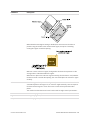
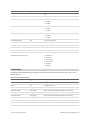
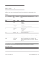
Precautions and Responsibilities
Precautions specified in IEC 60825-1 and FDA CFR Title 21 Part 1040 are as follows:
Gocator 2300 & 2880 Series
Safety and Maintenance • Laser Safety • 11
Requirement
Class 2M
Class 3R
Class 3B
Remote interlock
Not required
Not required
Required*
Key control
Not required
Not required
Required – cannot remove
key when in use*
Power-on delays
Not required
Not required
Required*
Beam attenuator
Not required
Not required
Required*
Emission indicator
Not required
Not required
Required*
Warning signs
Not required
Not required
Required*
Beam path
Not required
Terminate beam at useful
length
Terminate beam at useful
length
Specular reflection
Not required
Prevent unintentional
reflections
Prevent unintentional
reflections
Eye protection
Not required
Not required
Required under special
conditions
Laser safety officer
Not required
Not required
Required
Training
Not required
Required for operator and
maintenance personnel
Required for operator and
maintenance personnel
*LMI Class 3B laser components do not incorporate these laser safety items. These items must be added and completed by customers
in their system design.
Class 3B Responsibilities
LMI Technologies has filed reports with the FDA to assist customers in achieving certification of laser
products. These reports can be referenced by an accession number, provided upon request. Detailed
descriptions of the safety items that must be added to the system design are listed below.
Remote Interlock
A remote interlock connection must be present in Class 3B laser systems. This permits remote switches
to be attached in serial with the keylock switch on the controls. The deactivation of any remote switches
must prevent power from being supplied to any lasers.
Key Control
A key operated master control to the lasers is required that prevents any power from being supplied to
the lasers while in the OFF position. The key can be removed in the OFF position but the switch must not
allow the key to be removed from the lock while in the ON position.
Power-On Delays
A delay circuit is required that illuminates warning indicators for a short period of time before supplying
power to the lasers.
Beam Attenuators
A permanently attached method of preventing human access to laser radiation other than switches,
power connectors or key control must be employed. On some LMI laser sensors, the beam attenuator is
Gocator 2300 & 2880 Series
Safety and Maintenance • Laser Safety • 12
supplied with the sensor as an integrated mechanical shutter.
Emission Indicator
It is required that the controls that operate the sensors incorporate a visible or audible indicator when
power is applied and the lasers are operating. If the distance between the sensor and controls is more
than 2 meters, or mounting of sensors intervenes with observation of these indicators, then a second
power-on indicator should be mounted at some readily-observable position. When mounting the
warning indicators, it is important not to mount them in a location that would require human exposure
to the laser emissions. User must ensure that the emission indicator, if supplied by OEM, is visible when
viewed through protective eyewear.
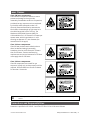
Warning Signs
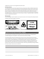
Laser warning signs must be located in the vicinity of the sensor such that they will be readily observed.
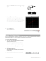
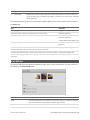
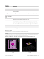
Examples of laser warning signs are as follows:
FDA warning sign example
IEC warning sign example
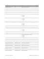
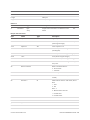
Nominal Ocular Hazard Distance (NOHD)
This is the distance from the source at which the intensity or the energy per surface unit becomes lower
than the Maximum Permissible Exposure (MPE) on the cornea and on the skin. The laser beam is
considered dangerous if the operator is closer from the source than the NOHD.
The following table shows the estimated NOHD for each Gocator model and laser class, assuming
continuous operation of the laser. As a configurable device the Gocator allows the user to set the laser
exposure (laser on-time) independently of the frame period (total cycle time for data acquisition).
Continuous operation of the laser means that the laser exposure is configured to be identical to the
frame period, which is also referred to as 100% duty cycle. However, in many applications the laser
exposure can be smaller than the frame period (less than 100% duty cycle) thereby reducing the NOHD.
The table therefore shows the worst-case NOHD.
Model
Laser Class
Line Fan Angle
NOHD (mm)
2x20
2M
28
259
2x30
2M
28
259
3R
28
900
3B
28
5759
Gocator 2300 & 2880 Series
Safety and Maintenance • Laser Safety • 13
Model
Laser Class
Line Fan Angle
NOHD (mm)
2x40
2M
28
259
3R
28
900
3B
28
5759
2M
28
259
3R
28
900
3B
28
5759
2M
43
251
3R
43
875
3B
43
3645
2M
57
245
3R
57
859
3B
57
2645
2x50
2x70
2x80
Systems Sold or Used in the USA
Systems that incorporate laser components or laser products manufactured by LMI Technologies
require certification by the FDA.
Customers are responsible for achieving and maintaining this certification.
Customers are advised to obtain the information booklet Regulations for the Administration and
Enforcement of the Radiation Control for Health and Safety Act of 1968: HHS Publication FDA 88-8035.
This publication, containing the full details of laser safety requirements, can be obtained directly from
the FDA, or downloaded from their web site at http://www.fda.gov/cdrh.
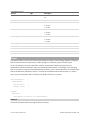
Electrical Safety
Failure to follow the guidelines described in this section may result in electrical shock or
equipment damage.
Sensors should be connected to earth ground
All sensors should be connected to earth ground through their housing. All sensors should be mounted
on an earth grounded frame using electrically conductive hardware to ensure the housing of the sensor
is connected to earth ground. Use a multi-meter to check the continuity between the sensor connector
and earth ground to ensure a proper connection.
Minimize voltage potential between system ground and sensor ground
Care should be taken to minimize the voltage potential between system ground (ground reference for
I/O signals) and sensor ground. This voltage potential can be determined by measuring the voltage
between Analog_out- and system ground. The maximum permissible voltage potential is 12 V but should
be kept below 10 V to avoid damage to the serial and encoder connections.
Gocator 2300 & 2880 Series
Safety and Maintenance • Electrical Safety • 14
See Gocator 2300 & 2880 I/O Connector (page 344) for a description of connector pins used with Gocator
2300 series sensors.
Use a suitable power supply
The +24 to +48 VDC power supply used with Gocator sensors should be an isolated supply with inrush
current protection or be able to handle a high capacitive load.
Use care when handling powered devices
Wires connecting to the sensor should not be handled while the sensor is powered. Doing so may cause
electrical shock to the user or damage to the equipment.
Environment and Lighting
Avoid strong ambient light sources
The imager used in this product is highly sensitive to ambient light hence stray light may have adverse
effects on measurement. Do not operate this device near windows or lighting fixtures that could
influence measurement. If the unit must be installed in an environment with high ambient light levels, a
lighting shield or similar device may need to be installed to prevent light from affecting measurement.
Avoid installing sensors in hazardous environments
To ensure reliable operation and to prevent damage to Gocator sensors, avoid installing the sensor in
locations
l
that are humid, dusty, or poorly ventilated;
l
with a high temperature, such as places exposed to direct sunlight;
l
where there are flammable or corrosive gases;
l
where the unit may be directly subjected to harsh vibration or impact;
l
where water, oil, or chemicals may splash onto the unit;
l
where static electricity is easily generated.
Ensure that ambient conditions are within specifications
Gocator sensors are suitable for operation between 0–50° C and 25–85% relative humidity (noncondensing). Measurement error due to temperature is limited to 0.015% of full scale per degree C.
The Master 400/800/1200/2400 is similarly rated for operation between 0–50° C.
The storage temperature is -30–70° C.
The sensor must be heat-sunk through the frame it is mounted to. When a sensor is properly
heat sunk, the difference between ambient temperature and the temperature reported in the
sensor's health channel is less
than 15° C.
Gocator sensors are high-accuracy devices, and the temperature of all of its components must
therefore be in equilibrium. When the sensor is powered up, a warm-up time of at least one
hour is required to reach a consistent spread of temperature in the sensor.
Gocator 2300 & 2880 Series
Safety and Maintenance • Environment and Lighting • 15
Sensor Maintenance
Keep sensor windows clean
Gocator sensors are high-precision optical instruments. To ensure the highest accuracy is achieved in all
measurements, the windows on the front of the sensor should be kept clean and clear of debris.
Use care when cleaning sensor windows
Use dry, clean air to remove dust or other dirt particles. If dirt remains, clean the windows carefully with
a soft, lint-free cloth and non-streaking glass cleaner or isopropyl alcohol. Ensure that no residue is left
on the windows after cleaning.
Turn off lasers when not in use
LMI Technologies uses semiconductor lasers in 3D measurement sensors. To maximize the lifespan of
the sensor, turn off the laser when not in use.
Avoid excessive modifications to files stored on the sensor
Settings for Gocator sensors are stored in flash memory inside the sensor. Flash memory has an
expected lifetime of 100,000 writes. To maximize lifetime, avoid frequent or unnecessary file save
operations.
Gocator 2300 & 2880 Series
Safety and Maintenance • Sensor Maintenance • 16
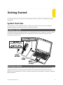
Getting Started
The following sections provide system and hardware overviews, in addition to installation and setup
procedures.
System Overview
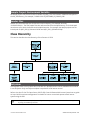
Gocator sensors can be installed and used in a variety of scenarios. Sensors can be connected as
standalone devices, dual-sensor systems, or multi-sensor systems.
Standalone System
Standalone systems are typically used when only a single Gocator sensor is required. The sensor can be
connected to a computer's Ethernet port for setup and can also be connected to devices such as
encoders, photocells, or PLCs.
Dual-Sensor System
In a dual-sensor system, two Gocator sensors work together to perform profiling and output the
combined results. The controlling sensor is referred to as the Main sensor, and the other sensor is
referred to as the Buddy sensor. Gocator's software recognizes three installation orientations: Opposite,
Wide, and Reverse.
Gocator 2300 & 2880 Series
17
A Master 400/800/1200/2400 must be used to connect two sensors in a dual-sensor system. Gocator
Power and Ethernet to Master cordsets are used to connect sensors to the Master.
Multi-Sensor System
Master 400/800/1200/2400 networking hardware can be used to connect two or more sensors into a
multi-sensor system. Gocator Master cordsets are used to connect the sensors to a Master. The Master
provides a single point of connection for power, safety, encoder, and digital inputs. A Master
400/800/1200/2400 can be used to ensure that the scan timing is precisely synchronized across
sensors. Sensors and client computers communicate via an Ethernet switch (1 Gigabit/s recommended).
Master 400/800/1200/2400 networking hardware does not support digital, serial, or analog output.
Gocator 2300 & 2880 Series
Getting Started • System Overview • 18
Gocator 2300 & 2880 Series
Getting Started • System Overview • 19
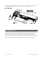
Hardware Overview
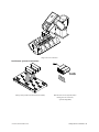
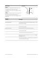
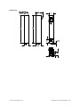
The following sections describe Gocator and its associated hardware.
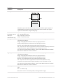
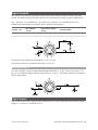
Gocator 2300 & 2880 Sensor
Gocator 2330
Item
Description
Camera
Observes laser light reflected from target surfaces.
Laser Emitter
Emits structured light for laser profiling.
I/O Connector
Accepts input and output signals.
Power / LAN Connector
Accepts power and laser safety signals and connects to 1000 Mbit/s Ethernet network.
Power Indicator
Illuminates when power is applied (blue).
Range Indicator
Illuminates when camera detects laser light and is within the target range (green).
Laser Indicator
Illuminates when laser safety input is active (amber).
Serial Number
Unique sensor serial number.
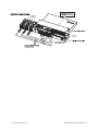
Gocator 2300 & 2880 Cordsets
Gocator 2300 and 2880 sensors use two types of cordsets.
The Power & Ethernet cordset provides power, laser safety interlock to the sensor. It is also used for
sensor communication via 1000 Mbit/s Ethernet with a standard RJ45 connector. The Master version of
the Power & Ethernet cordset provides direct connection between the sensor and a Master
400/800/1200/2400.
The Gocator I/O cordset provides digital I/O connections, an encoder interface, RS-485 serial connection,
and an analog output.
Gocator 2300 & 2880 Series
Getting Started • Hardware Overview • 20
The maximum cordset length is 60 m. See Gocator 2300 & 2880 I/O Connector (page 344) and for pinout
details.
See Parts and Accessories (page 357) for cordset lengths and part numbers. Contact LMI for information
on creating cordsets with customized lengths and connector orientations.
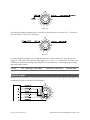
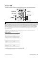
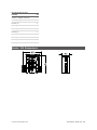
Master 100
The Master 100 is used by the Gocator 2300 series for standalone system setup.
Item
Description
Master Ethernet Port
Connects to the RJ45 connector labeled Ethernet on the Power/LAN to Master cordset.
Master Power Port
Connects to the RJ45 connector labeled Power/Sync on the Power/LAN to Master
cordset. Provides power and laser safety to the Gocator.
Sensor I/O Port
Connects to the Gocator I/O cordset.
Master Host Port
Connects to the host PC's Ethernet port.
Power
Accepts power (+48 V).
Power Switch
Toggles sensor power.
Laser Safety Switch
Toggles laser safety signal provided to the sensors [O= laser off, I= laser on].
Trigger
Signals a digital input trigger to the Gocator.
Encoder
Accepts encoder A, B and Z signals.
Digital Output
Provides digital output.
Gocator 2300 & 2880 Series
Getting Started • Hardware Overview • 21
See Master 100 (page 349) for pinout details.
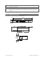
Master 400/800
The Master 400 and the Master 800 allow you to connect more than two sensors. The Master 400
accepts four sensors, and the Master 800 accepts eight sensors.
Item
Description
Sensor Ports
Master connection for Gocator sensors (no specific order required).
Ground Connection
Earth ground connection point.
Laser Safety
Laser safety connection.
Encoder
Accepts encoder signal.
Input
Accepts digital input.
See Master 400/800 (page 351) for pinout details.
Master 1200/2400
The Master 1200 and the Master 2400 allow you to connect more than two sensors. The Master 1200
accepts twelve sensors, and the Master 2400 accepts twenty-four sensors.
Gocator 2300 & 2880 Series
Getting Started • Hardware Overview • 22
Item
Description
Sensor Ports
Master connection for Gocator sensors (no specific order required).
Ground Connection
Earth ground connection point.
Laser Safety
Laser safety connection.
Encoder
Accepts encoder signal.
Input
Accepts digital input.
See Master 1200/2400 (page 354) for pinout details.
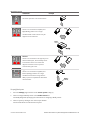
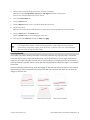
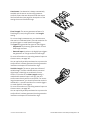
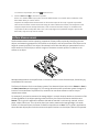
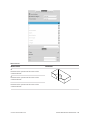
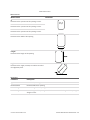
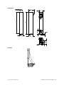
Calibration Targets
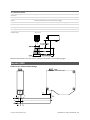
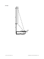
Targets are used for alignment and calibrating encoder systems.
Disks are typically used with systems containing a single sensor and can be ordered from LMI
Technologies. When choosing a disk for your application, select the largest disk that fits entirely within
the required field of view. See Parts and Accessories (page 357) for disk part numbers.
For wide, multi-sensor systems, bars are required to match the length of the system by following the
guidelines illustrated below. (LMI Technologies does not manufacture or sell bars.)
Gocator 2300 & 2880 Series
Getting Started • Hardware Overview • 23
See Aligning Sensors (page 84) for more information on alignment.
Gocator 2300 & 2880 Series
Getting Started • Hardware Overview • 24
Installation
The following sections provide grounding, mounting, and orientation information.
Grounding - Gocator
Gocators should be grounded to the earth/chassis through their housings and through the grounding
shield of the Power I/O cordset. Gocator sensors have been designed to provide adequate grounding
through the use of M5 x 0.8 pitch mounting screws. Always check grounding with a multi-meter to
ensure electrical continuity between the mounting frame and the Gocator's connectors.
The frame or electrical cabinet that the Gocator is mounted to must be connected to earth
ground.
Recommended Grounding Practices - Cordsets
If you need to minimize interference with other equipment, you can ground the Power & Ethernet or the
Power & Ethernet to Master cordset (depending on which cordset you are using) by terminating the
shield of the cordset before the split. The most effective grounding method is to use a 360-degree
clamp.
To terminate the cordset's shield:
1.
Expose the cordset's braided shield by cutting
the plastic jacket before the point where the
cordset splits.
Gocator 2300 & 2880 Series
Getting Started • Installation • 25
2.
Install a 360-degree ground clamp.
Grounding - Master 400/800/1200/2400
The mounting brackets of all Masters have been designed to provide adequate grounding through the
use of star washers. Always check grounding with a multi-meter by ensuring electrical continuity
between the mounting frame and RJ45 connectors on the front.
The frame or electrical cabinet that the Master is mounted to must be connected to earth
ground.
Mounting
Sensors should be mounted using four or six (depending on the model) M5 x 0.8 pitch screws of suitable
length. The recommended thread engagement into the housing is 8 - 10 mm. Proper care should be
taken in order to ensure that the internal threads are not damaged from cross-threading or improper
insertion of screws.
With the exception of Gocator 2880, sensors should not be installed near objects that might occlude a
camera's view of the laser. (Gocator 2880 is specifically designed to compensate for occlusions.)
Sensors should not be installed near surfaces that might create unanticipated laser reflections.
Gocator 2300 & 2880 Series
Getting Started • Installation • 26
The sensor must be heat sunk through the frame it is mounted to. When a sensor is properly
heat sunk, the difference between ambient temperature and the temperature reported in the
sensor's health channel is less than 15° C.
Gocator sensors are high-accuracy devices. The temperature of all of its components must be
in equilibrium. When the sensor is powered up, a warm-up time of at least one hour is required
to reach a consistent spread of temperature within the sensor.
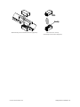
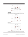
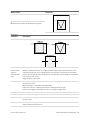
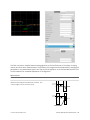
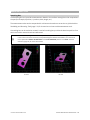
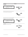
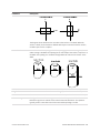
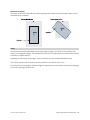
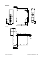
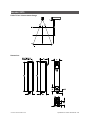
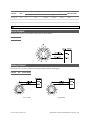
Orientations
The examples below illustrate the possible mounting orientations for standalone and dual-sensor
systems.
See Dual-Sensor System Layout (page 51) for more information on orientations.
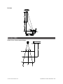
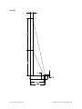
Standalone Orientations
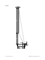
Single sensor above conveyor
Gocator 2300 & 2880 Series
Getting Started • Installation • 27
Single sensor on robot arm
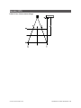
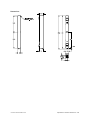
Dual-Sensor System Orientations:
Side-by-side for wide-area measurement (Wide)
Main must be on the left side (when
looking into the connector)
of the Buddy (Wide)
Gocator 2300 & 2880 Series
Getting Started • Installation • 28
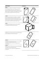
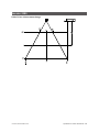
Above/below for two-sided measurement (Opposite)
Main must be on the top
with Buddy on the bottom (Opposite)
Gocator 2300 & 2880 Series
Getting Started • Installation • 29
Network Setup
The following sections provide procedures for client PC and Gocator network setup.
Client Setup
Sensors are shipped with the following default network configuration:
Setting
Default
DHCP
Disabled
IP Address
192.168.1.10
Subnet Mask 255.255.255.0
Gateway
0.0.0.0
All Gocator sensors are configured to 192.168.1.10 as the default IP address. For a dual-sensor
system, the Main and Buddy sensors must be assigned unique addresses before they can be
used on the same network. Before proceeding, connect the Main and Buddy sensors one at a
time (to avoid an address conflict) and use the steps in Running a Dual-Sensor System on page 33
to assign each sensor a unique address.
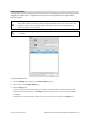
To connect to a sensor for the first time:
1.
Connect cables and apply power.
Sensor cabling is illustrated in
System Overview on page 17.
Gocator 2300 & 2880 Series
Getting Started • Network Setup • 30
2.
Change the client PC's network
settings.
Windows 7
a. Open the Control Panel, select
Network and Sharing
Center, and then click Change
Adapter Settings.
b. Right-click the network
connection you want to
modify, and then click
Properties.
c. On the Networking tab, click
Internet Protocol Version 4
(TCP/IPv4), and then click
Properties.
d. Select the Use the following
IP address option.
e. Enter IP Address "192.168.1.5"
and Subnet Mask
"255.255.255.0", then click OK.
Mac OS X v10.6
a. Open the Network pane in
System Preferences and
select Ethernet.
b. Set Configure to Manually.
c. Enter IP Address "192.168.1.5"
and Subnet Mask
"255.255.255.0", then click
Apply.
See Troubleshooting (page 320) if you experience any problems while attempting to establish a
connection to the sensor.
Gocator 2300 & 2880 Series
Getting Started • Network Setup • 31
Gocator Setup
The Gocator is shipped with a default configuration that will produce laser profiles on most targets.
The following sections walk you through the steps required to set up a standalone sensor system and a
dual-sensor system for operations. After you have completed the setup, you can perform laser profiling
to verify basic sensor operation.
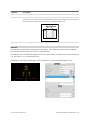
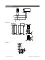
Running a Standalone Sensor System
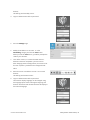
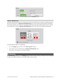
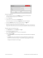
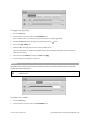
To configure a standalone sensor system:
1.
Power up the sensor.
The power indicator (blue) should turn on immediately.
2.
Enter the sensor's IP address (192.168.1.10) in a web
browser.
3.
Log in as Administrator with no password.
The interface display language can be changed using
the language option. After selecting the language, the
browser will refresh and the web interface will display in
the selected language.
4.
Go to the Manage page.
5.
Ensure that Replay mode is off (the slider is set to the
left).
6.
Ensure that the Laser Safety Switch is enabled or the
Laser Safety input is high.
7.
Go to the Scan page.
8.
Press the Start button or the Snapshot on the Toolbar
to start the sensor.
Master 200
The Start button is used to run sensors continuously,
Gocator 2300 & 2880 Series
Getting Started • Network Setup • 32
whereas the Snapshot button is used to trigger a single
capture.
Standalone
Master 400/800/1200/2400
9.
Move a target into the laser plane.
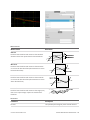
If a target object is within the sensor's measurement
range, the data viewer will display the shape of the
target, and the sensor's range indicator will illuminate.
If you cannot see the laser, or if a profile is not displayed
in the Data Viewer, see Troubleshooting (page 320).
10. Press the Stop button.
The laser should turn off.
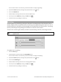
Running a Dual-Sensor System
All sensors are shipped with a default IP address of 192.168.1.10. Ethernet networks require a unique IP
address for each device, so you must set up a unique address for each sensor.
To configure a dual-sensor system:
1.
Turn off the sensors and unplug the Ethernet network
connection of the Main sensor.
All sensors are shipped with a default IP address of
192.168.1.10. Ethernet networks require a unique IP
address for each device. Skip step 1 to 3 if the Buddy
sensor's IP address is already set up with an unique
address.
2.
Power up the Buddy sensor.
The power LED (blue) of the Buddy sensor should turn
on immediately.
3.
Enter the sensor's IP address 192.168.1.10 in a web
Gocator 2300 & 2880 Series
Getting Started • Network Setup • 33
browser.
This will log into the Buddy sensor.
4.
Log in as Administrator with no password.
5.
Go to the Manage Page.
6.
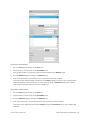
Modify the IP address to 192.168.1.11 in the
Networking category and click the Save button.
When you click the Save button, you will be prompted to
confirm your selection.
7.
Turn off the sensors, re-connect the Main sensor's
Ethernet connection and power-cycle the sensors.
After changing network configuration, the sensors must
be reset or power-cycled before the change will take
effect.
8.
Enter the sensor's IP address 192.168.1.10 in a web
browser.
This will log into the Main sensor.
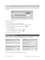
9.
Log in as Administrator with no password.
The interface display language can be changed using
the language option. After selecting the language, the
browser will refresh and the web interface will display in
the selected language.
Gocator 2300 & 2880 Series
Getting Started • Network Setup • 34
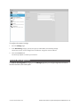
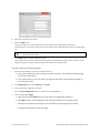
10. Select the Manage page.
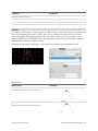
11. Go to Manage page, Sensor System panel, and select
the Visible Sensors panel.
The serial number of the Buddy sensor is listed in the
Available Sensors panel.
12. Select the Buddy sensor and click the Assign button.
The Buddy sensor will be assigned to the Main sensor
and its status will be updated in the System panel.
The firmware on Main and Buddy sensors must be the
same for Buddy assignment to be successful. If the
firmware is different, connect the Main and Buddy
sensor one at a time and follow the steps in Firmware
Upgrade on page 62 to upgrade the sensors.
13. Ensure that the Laser Safety Switch is enabled or the
Laser Safety input is high.
Master 400/800/1200/2400
14. Ensure that Replay mode is off (the slider is set to the
left).
15. Go to the the Scan page.
16. Press the Start or the Snapshot button on the
Toolbarto start the sensors.
The Start button is used to run sensors continuously,
while the Snapshot button is used to trigger a single
profile.
Gocator 2300 & 2880 Series
Getting Started • Network Setup • 35
17. Move a target into the laser plane.
If a target object is within the sensor's measurement
range, the data viewer will display the shape of the
target, and the sensor's range indicator will illuminate.
If you cannot see the laser, or if a profile is not displayed
in the Data Viewer, see Troubleshooting (page 320).
18. Press the Stop button if you used the Start button to
start the sensors.
The laser should turn off.
Next Steps
After you complete the steps in this section, the Gocator measurement system is ready to be configured
for an application using the software interface. The interface is explained in the following sections:
System Management and Maintenance (page 50)
Contains settings for sensor system layout, network, motion and alignment, handling jobs, and sensor
maintenance.
Scan Setup and Alignment (page 64)
Contains settings for scan mode, trigger source, detailed sensor configuration, and performing
alignment. Measurement (page 109)
Contains built-in measurement tools and their settings.
Output (page 179)
Contains settings for configuring output protocols used to communicate measurements to external
devices.
Dashboard (page 190)
Provides monitoring of measurement statistics and sensor health.
Toolbar (page 43)
Controls sensor operation, manages jobs, and replays recorded measurement data.
Gocator 2300 & 2880 Series
Getting Started • Next Steps • 36
Theory of Operation
The following sections describe the theory of operation of Gocator sensors.
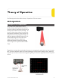
3D Acquisition
Principle of 3D Acquisition
The Gocator 2300 series sensors are line
profiler sensors, meaning that they capture a
single 3D profile for each camera exposure. The
sensor projects a laser line onto the target. The
sensor's camera views the laser from an angle,
and captures the reflection of the light off the
target. Because of this triangulation angle, the
laser line appears in different positions on the
camera depending on the 3D shape of the
target. Gocator sensors are always precalibrated to deliver 3D data in engineering
units throughout the specified measurement
range.
Target objects are typically moved under the sensor on a transportation mechanism, such as a conveyor
belt. The sensor captures a series of 3D slices, building up the full scan of the object. Sensor speed and
required exposure time to measure the target are typically critical factors in applications with line profiler
sensors.
Gocator 2300 & 2880 Series
37
Resolution and Accuracy
Delete this text and replace it with your own content.
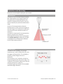
X Resolution
X resolution is the horizontal distance between
each measurement point along the laser line.
This specification is essentially based on the
number of camera columns used to cover the
field of view (FOV) at a particular measurement
range .
Since the FOV is trapezoidal, the distance
between points is closer at the near range than
at the far range. This is reflected in the Gocator
data sheet as the two numbers quoted for X
resolution.
X resolution is important for how accuratel the
width of a target can be measured.
NOTE: When the Gocator runs in Profile mode
and Uniform Spacing is enabled, the 3D data
is resampled to an X interval that is different
from the raw camera resolution.
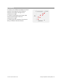
Z Resolution
Z resolution is the variability of the height
measurement, in each individual 3D point, with
the target at a fixed position. This variability is
caused by camera imager and sensor
electronics.
Like X resolution, the Z resolution is better at
the close range and worse at the far range. This
is reflected in the Gocator data sheet as the two
numbers quoted for Z resolution.
Z Resolution gives an indication of the smallest
detectable height difference.
Gocator 2300 & 2880 Series
Theory of Operation • 3D Acquisition • 38
Z Linearity
Z Linearity is the difference between the actual
distance to the target and the measured
distance to the target, throughout the
measurement range.
Z Linearity is expressed in the Gocator data
sheet as a percentage of the total
measurement range.
Z Linearity gives an indication of the sensor's
ability to measure absolute distance
Gocator 2300 & 2880 Series
Theory of Operation • 3D Acquisition • 39
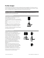
Profile Output
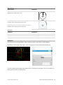
Gocator measures the height of the object calculated from laser triangulation. The Gocator reports a
series of ranges along the laser line, with each range representing the distance from the sensor's origin
plane. Each range contains a height and a position in the sensor's field of view. Coordinate Systems
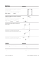
Range data is reported in sensor or system coordinates depending on the alignment state. The
coordinate systems are described below.
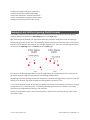
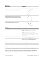
Sensor Coordinates
Before alignment, individual sensors use the
coordinate system shown here.
The Z axis represents the sensor's measurement
range (MR), with the values increasing towards the
sensor.
The X axis represents the sensor's field of view
(FOV).
The origin is at the center of the MR and FOV.
In Surfacedata, the Y axis represents the relative
position of the part in the direction of travel.
Y position increases as the object moves forward
(increasing encoder position).
System Coordinates
Alignment is used with a single sensor to
compensate for mounting misalignment and to
set a zero reference, such as a conveyor belt
surface. Alignment is also used to set a
common coordinate system for dual-sensor
systems. In both cases, alignment determines
the adjustments to X, Z, and tilt (rotation in the
X–Z plane) needed to align the data from each
sensor. The adjustments resulting from
alignment are called transformations. See
Alignment (page 83) for more information on
alignment.
System coordinates are aligned so that the
system X axis is parallel to the alignment target
surface. The system Z origin is set to the base of
the alignment target object. The tilt angle is
positive when rotating from the X to the Z axis.
Similar to the sensor coordinates, Y positions
increase when the encoder increases.
Gocator 2300 & 2880 Series
Theory of Operation • Profile Output • 40
For Wide and Opposite layouts, profiles and
measurements from the Main and Buddy
sensors are expressed in a unified coordinate
system. Isolated layouts express results using a
separate coordinate system for each sensor.
Resampled and Uniform Spacing Profile Format
Profile data produced in Profile mode is available in two formats: with and without uniform spacing.
Uniform spacing is enabled in the Scan Mode panel, on the Scan page.
With uniform spacing enabled, the ranges that make up a profile are resampled so that the spacing is
uniform along the laser line (X axis). The resampling divides the X axis into fixed size "bins." Profile points
that fall into the same bin are combined into a single range value (Z). The size of the spacing interval can
be set under the Spacing tab in the Sensor panel on Scan page.
As a result, in the Ethernet data channel, only the range values (Z) are reported and the X positions can
be reconstructed through the array index at the receiving end (the client).
Resampling to uniform spacing reduces the complexity for downstream algorithms to process the profile
data from the Gocator, but places a higher processing load on the sensor's CPU.
In contrast, the profile format without uniform spacing set requires no processing on the sensor. Ranges
are reported in (X, Z) coordinate pairs. This frees up processing resources in the Gocator, but usually
requires more complicated processing on the client side.
All built-in measurement tools in the Gocator operate on profiles with uniform spacing in both Profile
and Surface mode.
Gocator 2300 & 2880 Series
Theory of Operation • Profile Output • 41
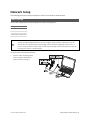
Gocator Web Interface
The following sections describe the Gocator web interface.
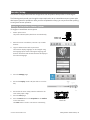
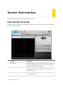
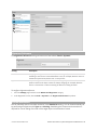
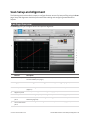
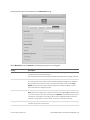
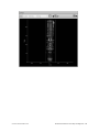
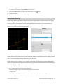
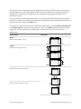
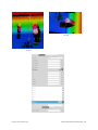
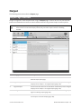
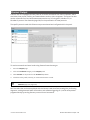
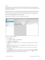
User Interface Overview
Gocator sensors are configured by connecting to a Main sensor with a web browser. The Gocator web
interface is illustrated below.
Element
Description
1
Manage page
Contains settings for sensor system layout, network, motion and
alignment, handling jobs, and sensor maintenance. See System
Management and Maintenance (page 50).
2
Scan page
Contains settings for scan mode, trigger source, detailed sensor
configuration, and performing alignment. See Scan Setup and
Alignment (page 64).
3
Measure page
Contains built-in measurement tools and their settings. See
Measurement (page 109).
Gocator 2300 & 2880 Series
42
Element
Description
4
Output page
Contains settings for configuring output protocols used to
communicate measurements to external devices. See Output
(page 179).
5
Dashboard page
Provides monitoring of measurement statistics and sensor health.
See Dashboard (page 190).
6
CPU Load and Speed
Provides important sensor performance metrics. See Metrics Area
(page 48).
7
Help
Provides links to the user manual and SDK.
8
Toolbar
Controls sensor operation, manages jobs, and replays recorded
measurement data. See Toolbar (below).
9
Configuration area
Provides controls to configure scan and measurement tool
settings.
10
Data viewer
Displays sensor data, tool setup controls, and measurements. See
Data Viewer on page 97 for its use when the Scan page is active
and on page 110 for its use when the Measure page is active.
11
Log
Displays messages from the sensor (errors, warnings, and other
information). See Log (page 48).
Common Elements
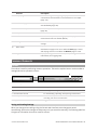
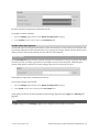
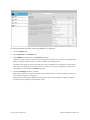
Toolbar
The toolbar is used for performing common operations. This section explains how to use the toolbar to
manage jobs and to operate the sensor.
Element
Description
1 Job controls
For saving and loading different jobs.
2 Recorded data controls
For downloading, uploading, and exporting recorded data.
3 Sensor operation / replay control
Use the sensor operation controls to start sensors, enable
recording, and control recorded data.
4 Replay switch
Toggles the sensor data source between live and replay.
Saving and Loading Settings
When you change sensor settings using the Gocator web interface, some changes are saved
automatically, while other changes are temporary until you save them manually. The following table lists
the types of information that can be saved in a sensor.
Gocator 2300 & 2880 Series
Gocator Web Interface • User Interface Overview • 43
Setting Type
Behavior
Network Address
Network address changes are saved when you click the Save button in Networking on
the Manage page. The sensor must be reset before changes take effect.
Job
Most of the settings that can be changed in the Gocator's web interface, such as the ones
in the Manage, Measure, and Output pages, are temporary until saved in a job file.
Each sensor can have multiple job files. If there is a job file that is designated as the
default, it will be loaded automatically when the sensor is reset.
Alignment
Alignment can either be fixed or dynamic, as controlled by the Alignment Reference
setting in Motion and Alignment in the Manage page.
Alignment is saved automatically at the end of the alignment procedure when
Alignment Reference is set to Fixed . When Alignment Reference is set to
Dynamic, however, you must manually save the job to save alignment.
The job drop-down list shows the list of jobs stored in the sensor. The job that is currently active is listed
at the top. The job name will be marked with "[unsaved]" to indicate any unsaved changes.
To save a job:
1.
2.
Select a job in the job drop-down list.
l
If you are creating a new job, choose [New] in the job drop-down list and enter a name for the job.
l
If you are saving changes to an existing job, choose the job in the job drop-down list.
Press the Enter key or click the Save button
.
The job will be saved to sensor storage using the name you provided. Saving a job automatically sets it
as the default, that is, the job loaded when then sensor is restarted.
To activate an existing job:
1.
Select an existing file name in the job drop-down list.
The job will be activated from sensor storage. If there are any unsaved changes to the current job, you
will be asked whether you want to discard those changes.
Detailed management of jobs is handled in the Jobs panel in the Manage page. See Jobs (page 57) for
more information.
Managing Multiple Settings
A Gocator can store several hundred jobs. Being able to switch between different jobs is useful when a
Gocator is used with different constraints during separate production runs (for example, width decision
constraints might be loose during one production run and tight during another depending on the
desired grade of the part).
Gocator 2300 & 2880 Series
Gocator Web Interface • User Interface Overview • 44
Switching active jobs can be done manually through the web interface as described under To activate an
existing job in Saving and Loading Settings on page 43. Switching active jobs can also be done
programmatically using the supported industrial protocols (Modbus, EtherNet/IP, and ASCII), the
Gocator’s native Ethernet protocol, and through the SDK.
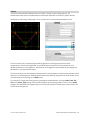
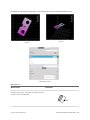
Recording, Playback, and Measurement Simulation
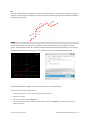
Gocator sensors can record and replay data, and can also simulate measurement tools on recorded data.
This feature is most often used for troubleshooting and fine-tuning measurements, but can also be
helpful during setup.
Recording and playback are controlled by using the toolbar controls.
Recording and playback controls when replay is off
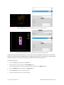
To record live data:
1.
Toggle Replay mode off by setting the slider to the left in the Toolbar.
2.
Press the Record button to enable recording.
When replay is off and recording is enabled, the sensor will store the most recent data as it runs.
Remember to disable recording if you no longer wish to record live data (press the Record button again
to disable recording).
3.
Press the Snapshot button or Start button.
The Snapshot records a single frame. The Start button will run the sensor continuously and all frames
will be recorded, up to available memory. When the memory limit is reached, the oldest data will be
discarded.
Newly recorded data is appended to existing replay data unless the sensor job has been
modified.
Gocator 2300 & 2880 Series
Gocator Web Interface • User Interface Overview • 45
Recording and playback controls when replay is on
To replay recorded data:
1.
Toggle Replay mode on by setting the slider to the right in the Toolbar.
The slider's background will turn blue and a Replay Mode Enabled message will be displayed.
2.
Use the Replay slider or the Step Forward, Step Back, or Play buttons to review data.
The Step Forward and Step Back buttons move and the current replay location backward and forward
by a single frame, respectively.
The Play button advances the replay location continuously, animating the playback.
The Stop button (replaces the Play button while playing) can be used to pause the replay at a particular
location.
The Replay slider (or Replay Position box) can be used to go to a specific replay frame.
To simulate measurements on recorded data:
1.
Toggle Replay mode on by setting the slider to the right in the Toolbar.
The slider's background will turn blue and a Replay Mode Enabled message will be displayed.
2.
Go to the Measure page.
Modify settings for existing measurements, add new measurement tools, or delete measurement tools
as desired.
3.
Use the Replay Slider, Step Forward, Step Back, or Play button to simulate measurements.
Step or play through recorded data to execute the measurement tools on the recording.
Individual measurement values can be viewed directly in the data viewer. Statistics on the
measurements that have been simulated can be viewed in the Dashboard page; see Dashboard (page
190).
To clear recorded data:
1.
Stop the sensor if it is running by clicking on the Stop button.
2.
Click on the Clear Replay Data button
.
Downloading, Exporting, and Uploading Recorded Data
Recorded data can be downloaded or exported to the client computer or uploaded to the Gocator. Export is often used for processing the recorded data using third-party tools. Recorded data can also be
downloaded in a binary format, which is used to back up the data for reviewing in the future.
Recorded data is not saved or loaded when you save or activate jobs in the toolbar.
Gocator 2300 & 2880 Series
Gocator Web Interface • User Interface Overview • 46
To download recorded data:
1.
Toggle Replay mode on by setting the slider to the right in the Toolbar.
The slider's background will turn blue and a Replay Mode Enabled message will be displayed.
2.
Click the Download button
.
To upload recorded data:
1.
Toggle Replay mode on by setting the slider to the left in the Toolbar.
The slider's background will turn blue and a Replay Mode Enabled message will be displayed.
2.
Click the Upload button
.
3.
Select the directory and the file name to upload from the client computer and click on OK.
Recorded data can be exported using the CSV format. If Acquire Intensity has been enabled in the
Scan Mode panel on the Scan page, intensity data will be included in the exported CSV file.
To export recorded data to CSV:
1.
Toggle Replay mode on by setting the slider to the right in the Toolbar.
The slider's background will turn blue and a Replay Mode Enabled message will be displayed.
2.
Click the Export button
and select Export Range Data as CSV.
In Profile mode, all data in the record buffer is exported. In Surface mode, only data at the current
replay location is exported.
Use the playback control buttons to move to a different replay location; see To replay recorded data in
Recording, Playback, and Measurement Simulation on page 45 for more information on playback.
3.
Optionally, convert exported data to another format using the CSV Converter Tool on page 318.
Recorded intensity data can be exported to a bitmap (.BMP format). Acquire Intensity must be
checked in the Scan Mode panel while data was being recorded in order to export intensity data.
Gocator 2300 & 2880 Series
Gocator Web Interface • User Interface Overview • 47
To export recorded intensity data to BMP:
1.
Toggle Replay mode on by setting the slider to the right in the Toolbar.
The slider's background will turn blue and a Replay Mode Enabled message will be displayed.
2.
Click the Export button
and select Intensity data as BMP.
Only the intensity data in the current replay location is exported.
Use the playback control buttons to move to a different replay location; see To replay recorded data in
Recording, Playback, and Measurement Simulation on page 45 for more information on playback.
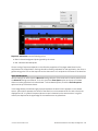
Log
The log, located at the bottom of the web interface, is a centralized location for all messages that the
Gocator displays, including warnings and errors.
To use the log:
1.
Click on the Log open button
at the bottom of the web interface.
2.
Click on the appropriate tab for the information you need.
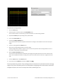
Metrics Area
The Metrics area displays two important sensor performance metrics: CPU load and speed (current
frame rate).
The CPU bar in the Metrics panel (at the top of the interface) displays how much of the CPU is being
utilized. A warning symbol ( ) will appear next to the CPU bar if the sensor drops profiles because the
CPU is over-loaded.
CPU at 100%
CPU warning message
The Speed bar displays the frame rate of the sensor. A warning symbol ( ) will appear next to it if
triggers (external input or encoder) are dropped because the external rate exceeds the maximum frame
rate.
In both cases, a warning message will be temporarily displayed in the lower right corner of the web
interface. Click on the warning symbol ( ) to redisplay the warning message.
Open the log for details on the warning. See Log (above) for more information.
Gocator 2300 & 2880 Series
Gocator Web Interface • User Interface Overview • 48
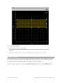
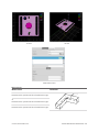
Data Viewer
The data viewer is displayed in both the Scan and the Measure pages, but displays different
information depending on which page is active.
When the Scan page is active, the data viewer displays sensor data and can be used to adjust regions of
interest. Depending on the selected operation mode (page 65), the data viewer can display video images,
3D profiles, or 3D surfaces. For details, see Data Viewer (page 97).
When the Measure page is active, the data viewer displays sensor data onto which representations of
measurement tools and their measurements are superimposed. For details, see Data Viewer (page 110).
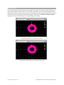
Because Gocator 2880 has two cameras, two profiles are displayed in the Gocator web
interface.
Gocator 2300 & 2880 Series
Gocator Web Interface • User Interface Overview • 49
System Management and Maintenance
The following sections describe how to set up the sensor connections and networking, how to calibrate
encoders and choose alignment reference, and how to perform maintenance tasks.
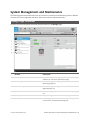
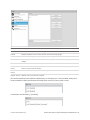
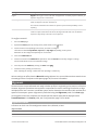
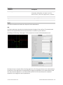
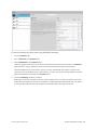
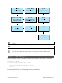
Manage Page Overview
Gocator's system and maintenance tasks are performed on the Manage page.
Element
Description
1
Sensor System
Contains settings for configuring sensor system and layout,
and boot-up. See Sensor System (next page).
2
Networking
Contains settings for configuring the network. See
Networking (page 54).
3
Motion and Alignment
Contains settings to configure the encoder. See Motion and
Alignment (page 55).
4
Jobs
Lets you manage jobs stored on the sensor. See Jobs (page
57).
5
Security
Lets you change passwords. See Security (page 59).
6
Maintenance
Lets you upgrade firmware, create/restore backups, and
reset sensors. See Maintenance (page 60).
Gocator 2300 & 2880 Series
Gocator Web Interface • System Management and Maintenance • 50
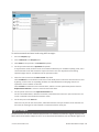
Sensor System
The following sections describe the Sensor System category on the Manage page. This category lets
you choose the layout standalone or dual-sensor systems, and provides other system settings.
Dual-sensor layouts are only displayed when a Buddy sensor has been assigned.
Sensor Autostart
With the Autostart setting enabled, laser ranging profiling and measurement functions will begin
automatically when the sensor is powered on. Autostart must be enabled if the sensor will be used
without being connected to a computer.
To enable/disable Autostart:
1.
Go to the Manage page and click on the Sensor System category.
2.
Check/uncheck the Autostart option in the Main section.
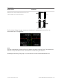
Dual-Sensor System Layout
Mounting orientations must be specified for a dual-sensor system. This information allows the
alignment procedure to determine the correct system-wide coordinates for laser profiling and
measurements. See Coordinate Systems (page 40) for more information on sensor and system
coordinates.
Gocator 2300 & 2880 Series
Gocator Web Interface • System Management and Maintenance • 51
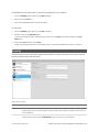
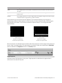
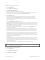
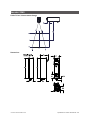
Supported Layouts
Orientation
Example
Standalone
The sensor operates as an isolated device.
Wide
Sensors are mounted in Left (Main) and
Right (Buddy) positions for a larger
combined field of view. Sensors may be
angled to avoid occlusions.
Reverse
Sensors are mounted in a left-right layout as
with the Wide layout, but the Buddy sensor
is mounted such that it is rotated 180
degrees around the Z axis to prevent
occlusion along the Y axis.
Opposite
Sensors are mounted in Top (Main) and
Bottom (Buddy) positions for a larger
combined measurement range and the
ability to perform Top/Bottom differential
measurements.
To specify the layout:
1.
Go to the Manage page and click on the Sensor System category.
2.
Select an assigned Buddy sensor in the Visible Sensors list.
See Buddy Assignment (next page) for information on assigning a Buddy Sensor.
3.
Select a layout by clicking on one of the Layout buttons.
See the table above for information on layouts.
Gocator 2300 & 2880 Series
Gocator Web Interface • System Management and Maintenance • 52
Buddy Assignment
In a dual-sensor system, the Main sensor assumes control of the Buddy sensor after the Buddy sensor is
assigned to the Main sensor. Configuration for both sensors can be performed through the Main
sensor's interface.
Main and Buddy sensors must be assigned unique IP addresses before they can be used on the
same network. Before proceeding, connect the Main and Buddy sensors one at a time (to avoid
an address conflict) and use the steps outline in Running a Dual-Sensor System (page 30) to
assign each sensor a unique address.
When a sensor is acting as a Buddy, it is not discoverable and its web interface is not
accessible.
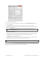
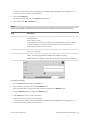
To assign a Buddy sensor:
1.
Go to the Manage page and click on the Sensor System category.
2.
Select a sensor in the Visible Sensors list.
3.
Click the Assign button.
A sensor can only be assigned as a Buddy if its firmware and model number match the firmware and
model number of the Main sensor. The Assign button will be greyed out if a sensor cannot be assigned
as a Buddy.
The Buddy sensor will be assigned to the Main sensor and its status will be updated in the System panel.
Gocator 2300 & 2880 Series
Gocator Web Interface • System Management and Maintenance • 53
To remove a Buddy, click on the Remove button.
Exposure Multiplexing
If the Main and Buddy sensors are mounted such that the camera from one sensor can detect the laser
from the other sensor, the Exposure Multiplexing option can be used to eliminate laser interference.
This setting creates a time offset for laser exposures and ensures that interfering lasers are not strobed
at the same time. Using the Exposure Multiplexing option may reduce the maximum frame rate.
To enable/disable exposure multiplexing:
1.
Go to the Manage page and click on the Sensor System category.
2.
In the Layout section, check/uncheck the Exposure Multiplexing option.
This option is only displayed if a buddy is assigned.
Networking
The Networking category on the Manage page provides network settings. Settings must be configured
to match the network to which the Gocator sensors are connected.
Gocator 2300 & 2880 Series
Gocator Web Interface • System Management and Maintenance • 54
To configure the network settings:
1.
Go to the Manage page.
2.
In the Networking category, specify the Type, IP, Subnet Mask, and Gateway settings.
The Gocator sensor can be configured to use DHCP or assigned a static IP address.
3.
Click on the Save button.
You will be prompted to confirm your selection.
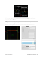
Motion and Alignment
The Motion and Alignment category on the Manage page lets you configure alignment reference,
encoder resolution, and travel speed.
Gocator 2300 & 2880 Series
Gocator Web Interface • System Management and Maintenance • 55
Alignment Reference
The Alignment Reference setting can have one of two values: Fixed or Dynamic.
Setting
Description
Fixed
A single global alignment is used for all jobs. This is typically used when the sensor
mounting is constant over time and between scans, for example, when the sensor is
mounted in a permanent position over a conveyor belt.
Dynamic
A separate alignment is used for each job. This is typically used when the sensor’s
position relative to the object scanned is always changing, for example, when the
sensor is mounted on a robot arm moving to different scanning locations.
To configure alignment reference:
1.
Go to the Manage page and click on the Motion and Alignment category.
2.
In the Alignment section, choose Fixed or Dynamic in the Alignment Reference drop-down.
Encoder Resolution
You can manually enter the encoder resolution in the Resolution setting , or it can be automatically set
by performing an alignment with Type set to Moving. Establishing the correct encoder resolution is
required for correct scaling of the scan of the target object in the direction of travel.
Gocator 2300 & 2880 Series
Gocator Web Interface • System Management and Maintenance • 56
Encoder resolution is expressed in millimeters per tick.
To configure encoder resolution:
1.
Go to the Manage page and click on the Motion and Alignment category.
2.
In the Encoder section, enter a value in the Resolution field.
Encoder Value and Frequency
The encoder value and frequency are used to confirm the encoder is correctly wired to the Gocator and
to manually calibrate encoder resolution (that is, by moving the conveyor system a known distance and
making a note of the encoder value at the start and end of movement).
Travel Speed
The Travel Speed setting is used to correctly scale scans in the direction of travel in systems that lack an
encoder but have a conveyor system that is controlled to move at constant speed. Establishing the
correct travel speed is required for correct scaling of the scan in the direction of travel.
Travel speed is expressed in millimeters per second.
To manually configure travel speed:
1.
Go to the Manage page and click on the Motion and Alignment category.
2.
In the Speed section, enter a value in the Travel Speed field.
Travel speed can also be set automatically by performing an alignment with Type set to Moving (see
page 84).
Jobs
The Jobs category on the Manage page lets you manage the jobs stored on the sensor.
Gocator 2300 & 2880 Series
Gocator Web Interface • System Management and Maintenance • 57
Element
Description
Name field
Used to provide a job name when saving files.
Jobs list
Displays the jobs that are currently saved in the sensor's flash storage.
Save button
Saves current settings to the job using the name in the Job Name field.
Load button
Loads the job that is selected in the file list. Reloading the current job discards any unsaved
changes.
Delete button
Deletes the job that is selected in the jobs list.
Set as Default
Sets the selected job as the default to be loaded at boot time. When the default job is selected, this
button
button is used to clear the default.
Download...
Downloads the selected jobs to the client computer.
button
Upload... button Uploads a job from the client computer.
Jobs can be loaded and set as default independently. For example, Job1 could be loaded, while Job2 is
set as the default. Default jobs load automatically when a sensor is power cycled or reset.
Unsaved jobs are indicated by "[unsaved]".
Gocator 2300 & 2880 Series
Gocator Web Interface • System Management and Maintenance • 58
To download, load, or delete a job, or to set one as a default or clear a default:
1.
Go to the Manage page and click on the Jobs category.
2.
Select a job in the Jobs list.
3.
Click on the appropriate button for the operation.
To save a job:
1.
Go to the Manage page and click on the Jobs category.
2.
Provide a name in the Job Name field.
To save an existing job under a different name, click on it in the Jobs list and then modify it in the Job
Name field.
3.
Click on the Save button or press Enter.
Saving a job automatically sets it as the default, that is, the job loaded when then sensor is restarted.
Security
Gocator sensors can be secured with passwords to prevent unauthorized access. Each sensor has two
accounts: Administrator and Technician.
Gocator Account Types
Account
Description
Administrator The Administrator account has privileges to use the toolbar (loading and saving jobs, recording and
viewing replay data), to view all pages and edit all settings, and to perform setup procedures such as
sensor alignment.
Technician
The Technician account has privileges to use the toolbar (loading and saving jobs, recording and
viewing replay data), to view the Dashboard page, and to start or stop the sensor.
Gocator 2300 & 2880 Series
Gocator Web Interface • System Management and Maintenance • 59
The Administrator and Technician accounts can be assigned unique passwords. By default, passwords
are blank (empty).
To set or change the password for the Administrator account:
1.
Go to the Manage page and click on the Security category.
2.
In the Administrator section, enter the Administrator account password and password confirmation.
3.
Click Change Password.
The new password will be required the next time that an administrator logs in to the sensor.
To set or change the password for the Technician account:
1.
Go to the Manage page and click on the Security category.
2.
In the Technician section, enter the Technician account password and password confirmation.
3.
Click Change Password.
The new password will be required the next time that a technician logs in to the sensor.
If the administrator or technician password is misplaced, the sensor can be recovered using a special
software tool. See Sensor Recovery Tool (page 311) for more information.
Maintenance
The Maintenance category in the Manage page is used to do the following:
l
upgrade the firmware and check for firmware updates;
l
back up and restore all saved jobs and recorded data;
l
restore the sensor to factory defaults;
l
reset the sensor.
Gocator 2300 & 2880 Series
Gocator Web Interface • System Management and Maintenance • 60
Sensor Backups and Factory Reset
You can create sensor backups, restore from a backup, and restore to factory defaults in the
Maintenance category.
Backup files contain all of the information stored on a sensor, including jobs and alignment.
An Administrator should create a backup file in the unlikely event that a sensor fails and a
replacement sensor is needed. If this happens, the new sensor can be restored with the backup
file.
To create a backup:
1.
Go to the Manage page and click on the Maintenance category.
2.
Click the Backup... button under Backup and Restore.
3.
When you are prompted, save the backup.
Backups are saved as a single archive that contains all of the files from the sensor.
Gocator 2300 & 2880 Series
Gocator Web Interface • System Management and Maintenance • 61
To restore from a backup:
1.
Go to the Manage page and click on the Maintenance category.
2.
Click the Restore... button under Backup and Restore.
3.
When you are prompted, select a backup file to restore.
The backup file is uploaded and then used to restore the sensor. Any files that were on the sensor
before the restore operation will be lost.
To restore a sensor to its factory default settings:
1.
Go to the Manage page and click on Maintenance.
2.
Consider making a backup.
Before proceeding, you should perform a backup. Restoring to factory defaults cannot be undone.
3.
Click the Factory Restore... button under Factory Restore.
You will be prompted whether you want to proceed.
Firmware Upgrade
LMI recommends routinely updating firmware to ensure that Gocator sensors always have the latest
features and fixes.
In order for the Main and Buddy sensors to work together, they must be use the same firmware
version. This can be achieved by upgrading through the Main sensor or by upgrading each
sensor individually.
To download the latest firmware:
1.
Go to the Manage page and click on the Maintenance category.
2.
Click the Check Updates... button in the Firmware section.
3.
Download the latest firmware.
Gocator 2300 & 2880 Series
Gocator Web Interface • System Management and Maintenance • 62
If a new version of the firmware is available, follow the instructions to download it to the client
computer.
If the client computer is not connected to the Internet, firmware can be downloaded and transferred to
the client computer by using another computer to download the firmware from LMI's website:
http://www.lmi3D.com/support/downloads.
To upgrade the firmware:
1.
Go to the Manage page and click on the Maintenance category.
2.
Click the Upgrade... button in the Firmware section.
3.
Provide the location of the firmware file in the File dialog.
4.
Wait for the upgrade to complete.
After the firmware upgrade is complete, the sensor will self-reset. If a buddy has been assigned, it will
be upgraded and reset automatically.
Gocator 2300 & 2880 Series
Gocator Web Interface • System Management and Maintenance • 63
Scan Setup and Alignment
The following sections describe the steps to configure Gocator sensors for laser profiling using the Scan
page. Setup and alignment should be performed before adding and configuring measurements or
outputs.
Scan Page Overview
The Scan page lets you configure sensors and perform alignment.
Element
Description
1
Scan Mode panel
Contains settings for the current scan mode (Video, Profile, or Surface) and other options.
See Scan Modes (next page) .
2
Trigger panel
Contains trigger source and trigger-related settings. See Triggers (page 66) .
3
Sensor panel
Contains settings for an individual sensor, such as active area or exposure. See Sensor
(page 71) .
4
Alignment panel
Used to perform alignment. See Alignment (page 83) .
5
Filters panel
Contains settings for post-processing of the profiles. See Filters (page 88) .
6
Part Detection
Used to set the part detection logic for sorting profiles into discrete objects. See Part
panel
Detection (page 93) .
7
Surface Generation Contains settings for surface generation. See Surface Generation (page 91) .
panel
Gocator 2300 & 2880 Series
Gocator Web Interface • Scan Setup and Alignment • 64
8
Element
Description
Data Viewer
Displays sensor data and adjust regions of interest. Depending on the current operation
mode, the data viewer can display video images , profile plots, or surface views . See Data
Viewer (page 97) .
The following table provides quick references for specific goals that you can achieve from the panels in
the Scan page.
Goal
Reference
Select a trigger source that is appropriate for the application.
Triggers (next page)
Ensure that camera exposure is appropriate for laser profiling .
Exposure (page 74)
Find the right balance between profile quality, speed, and CPU utilization.
Active Area (page 71)
Exposure (page 74)
Gocator Device Files (page 193)
Specify mounting orientations for dual-sensor systems.
Dual-Sensor System Layout
(page 51)
Calibrate the system so that laser profile data can be aligned to a common
Aligning Sensors (page 84)
reference and values can be correctly scaled in the axis of motion.
Set up the part detection logic to create discrete objects from surfaces or profiles. Part Detection (page 93)
Specify smoothing, gap-filling, and resampling parameters to remove effects of
Filters (page 88)
occlusions.
Scan Modes
The Gocator web interface supports threescan modes: Video, Profile, and Surface. The scan mode can
be selected in the Scan Mode panel.
Mode and Option
Description
Video
Outputs video images from the Gocator. This mode is useful for configuring exposure
time and troubleshooting stray light or ambient light problems.
Profile
Gocator 2300 & 2880 Series
Outputs profiles and performs profile measurements. Video images are processed
Gocator Web Interface • Scan Setup and Alignment • 65
Mode and Option
Description
internally to produce laser profiles and cross-sectional measurements.
Surface
Outputs 3D point clouds made up of many laser profiles combined together and
performs surface measurements. The sensor uses various methods to generate a
surface (see page 91). Part detection can be enabled on a surface to identify discrete
parts (see page 93).
Uniform Spacing
When this option is enabled, ranges are resampled to a uniform spacing along the X
axis (see page 41 for more information). The size of the spacing can be set in the
Spacing tab (see page 80).
When the option is disabled, the Gocator outputs unprocessed range data. Ranges are
reported in (x,z) coordinate pairs. Disable this option to extract ranges from the
Gocator at the highest possible rate. Post-profiling processing and measurements are
disabled.
This option is not available when in Surface mode.
When this option is enabled, an intensity value will be produced for each laser profile
point.
Acquire Intensity
Triggers
A trigger is an event that causes a sensor to take a single picture. Triggers are configured in the Trigger
panel on the Scan page.
When a trigger is processed, the laser is strobed and the camera exposes to produce an image. The
resulting image is processed inside the sensor to yield a profile (range/distance information), which can
then be used for measurement.
The laser and camera inside a sensor can be triggered by one of the following sources:
Trigger Source
Description
Time
Sensors have an internal clock that can be used to generate fixed-frequency triggers.
The external input can be used to enable or disable the time triggers.
Encoder
An encoder can be connected to provide triggers in response to motion. Three encoder
triggering behaviors are supported. These behaviors are set using the Behavior setting.
Ignore Backward
A scan is triggered when the target object moves forward. If the target object moves
backward, it must move forward by at least the distance that the target travelled
backward, plus one encoder spacing, to trigger the next scan.
Gocator 2300 & 2880 Series
Gocator Web Interface • Scan Setup and Alignment • 66
Trigger Source
Description
Track Backward
A scan is triggered only when the target object moves forward. If the target object
moves backward, it must move forward by at least the distance of one encoder spacing
to trigger the next scan.
Bi-directional
A scan is triggered when the target object moves forward or backward.
When triggers are received at a frequency higher than the maximum frame rate, some
Gocator 2300 & 2880 Series
Gocator Web Interface • Scan Setup and Alignment • 67
Trigger Source
Description
triggers may not be accepted. The Trigger Drops Indicator in the Dashboard can be
used to check for this condition.
The external input can be used to enable or disable the encoder triggers.
See Encoder Input (page 346) for more information on connecting the encoder to
Gocator sensors.
External Input
A digital input can provide triggers in response to external events (e.g., photocell).
When triggers are received at a frequency higher than the maximum frame rate, some
triggers may not be accepted. The Trigger Drops Indicator in the Dashboard page can
be used to check for this condition.
See Digital Inputs (page 345) for more information on connecting external input to
Gocator sensors.
Software
A network command can be used to send a software trigger. See Protocols (page 240)
for more information.
For examples of typical real-world scenarios, see below. For information on the settings used with each
trigger source, see next page
Trigger Examples
Example: Encoder + Conveyor
Encoder triggering is used to perform profile
measurements at a uniform spacing.
The speed of the conveyor can vary while the
object is being measured; an encoder ensures
that the measurement spacing is consistent,
independent of conveyor speed.
Example: Time + Conveyor
Time triggering can be used instead of encoder
triggering to perform profile measurements at a
fixed frequency.
Measurement spacing will be non-uniform if the
speed of the conveyor varies while the object is
being measured.
It is strongly recommended to use an encoder
with transport-based systems due to the
difficulty in maintaining constant transport
velocity.
Gocator 2300 & 2880 Series
Gocator Web Interface • Scan Setup and Alignment • 68
Example: External Input + Conveyor
External input triggering can be used to
produce a snapshot for profile measurement.
For example, a photocell can be connected as
an external input to generate a trigger pulse
when a target object has moved into position.
An external input can also be used to gate the
trigger signals when time or encoder triggering
is used. For example, a photocell could generate
a series of trigger pulses as long as there is a
target in position.
Example: Software Trigger + Robot Arm
Software triggering can be used to produce a
snapshot for profile measurement.
A software trigger can be used in systems that
use external software to control the activities of
system components.
Trigger Settings
The trigger source is selected using the Trigger panel in the Scan page.
After specifying a trigger source, the Trigger panel shows the parameters that can be configured. Parameter
Trigger Source
Description
Source
All
Selects the trigger source (Time, Encoder, External Input, or
Gocator 2300 & 2880 Series
Gocator Web Interface • Scan Setup and Alignment • 69
Parameter
Trigger Source
Description
Software).
Frame Rate
Time
Controls the frame rate. Select Max Speed from the dropdown to lock to the maximum frame rate. Fractional values are
supported. For example, 0.1 can be entered to run at 1 frame
every 10 seconds.
Gate on External Input
Time, Encoder
External input can be used to enable or disable profiling in a
sensor. When this option is enabled, the sensor will respond to
time or encoder triggers only when the external input is
asserted.
This setting is not displayed when Surface Generation is set
to Fixed Length, Variable Length, or Rotational (see page
91).
See See Digital Inputs (page 345) for more information on
connecting external input to Gocator sensors.
Behavior
Encoder
Specifies how the Gocator sensor is triggered when the target
moves. Can be Track Backward, Ignore Backward, or BiDirectional. See Triggers (page 66) for more information on
these behaviors.
Spacing
Encoder
Specifies the distance between triggers (mm). Internally the
Gocator sensor rounds the spacing to a multiple of the encoder
resolution.
Units
External Input, Software Specifies whether the trigger delay, output delay, and output
scheduled command operate in the time or the encoder
domain. The unit is implicitly set to microseconds with Time
trigger source, and millimeters with Encoder trigger source.
Trigger Delay
External Input
Controls the amount of time or the distance the sensor waits
before producing a frame after the external input is activated.
This is used to compensate for the positional difference
between the source of the external input trigger (e.g.,
photocells) and the sensor.
Trigger delay is only supported in single exposure mode; for
details, see Exposure (page 74) .
Depending on the surface generation settings, some trigger options may not be available.
To configure the trigger source:
1.
Go to the Scan page.
2.
Expand the Trigger panel by clicking on the panel header.
3.
Select the trigger source from the drop-down.
4.
Configure the settings.
See the trigger parameters above for more information.
5.
Save the job in the Toolbar by clicking the Save button
Gocator 2300 & 2880 Series
.
Gocator Web Interface • Scan Setup and Alignment • 70
Sensor
The following sections describe the settings that are configured in the Sensor panel on the Scan page.
Active Area
Active area refers to the region within the sensor's maximum field of view that is used for laser profiling.
By default, the active area covers the sensor's entire field of view. By reducing the active area, the sensor
can operate at higher speeds.
Active area is specified in sensor coordinates,
rather than in system coordinates. As a result, if
the sensor is already alignment calibrated, press
the Acquire button to display uncalibrated data
before configuring the active area. See Coordinate
Systems (page 40) for more information on sensor
and system coordinates.
To set the active area:
1.
Go to the Scan page.
2.
Choose Profile or Surface mode in the Scan Mode panel.
If one of these modes is not selected, you will not be able to configure the active area.
3.
Expand the Sensor panel by clicking on the panel header or the
Gocator 2300 & 2880 Series
button.
Gocator Web Interface • Scan Setup and Alignment • 71
4.
Click the button corresponding to the sensor you want to configure.
The button is labeled Top, Bottom, Top-Left, or Top-Right, depending on the system.
Active area is specified separately for each sensor.
5.
Click on the Active Area tab.
6.
Click the Select button.
7.
Click the Acquire button to see a scan while setting the active area.
8.
Set the active area.
Enter the active area values in the edit boxes or adjust the active area graphically in the data viewer.
9.
Click the Save button in the Sensor panel.
Click the Cancel button to cancel setting the active area.
10. Save the job in the Toolbar by clicking the Save button
.
Laser profiling devices are usually more accurate at the near end of their measurement range.
If your application requires a measurement range that is small compared to the maximum
measurement range of the sensor, mount the sensor so that the active area can be defined at
the near end of the measurement range.
Tracking Window
The Gocator can track a relatively flat object in real-time to achieve very high scan rates. This feature
tracks the object height using a small window that moves dynamically to cover a larger measurement
range. You can balance the gain in speed and the tracking ability by configuring the size of the tracking
area. This feature is typically used in road or web scanning applications where the target is a continuous
flat surface.
A laser line remains tracked as long as the percentage of detected laser points exceeds the user-defined
search threshold. When the sensor loses track of the laser line, the sensor will search for the laser line
using the full active area.
Gocator 2300 & 2880 Series
Gocator Web Interface • Scan Setup and Alignment • 72
To enable the tracking window:
1.
Go to the Scan page.
2.
Choose Profile or Surface mode in the Scan Mode panel.
If one of these modes is not selected, you will not be able to set the tracking window.
3.
Expand the Sensor panel by clicking on the panel header.
4.
Click on the Active Area tab.
5.
Check the Tracking Window box.
The panel below the checkbox expands and shows the settings for the window used to track the object
height.
6.
Click the tracking window's Select button.
7.
Resize the tracking window shown in the data viewer.
Only the height of the window is required. You can move the position of the tracking window to cover a
live profile to help adjust the window height.
8.
Edit the Search Threshold setting.
The search threshold defines the minimum percentage of the points detected across the profile for the
laser to be considered tracked. If tracking is lost, the sensor will search for the laser using the full active
area.
9.
Click the Save button in the Sensor panel.
10. Save the job in the Toolbar by clicking the Save button
.
The sensor adjusts the position of the tracking window so that the area is centered around the average
height of the entire visible laser profile. You should adjust the lighting and the active area to remove all
background objects, such as the conveyor belt surface, ambient lights, etc.
Gocator 2300 & 2880 Series
Gocator Web Interface • Scan Setup and Alignment • 73
Transformations
The transformation settings are used to control how profiles are converted from sensor coordinates to
system coordinates.
Parameter
Description
X Offset
Specifies the shift along the X axis. With Normal orientation, a positive value shifts the profiles to
the right. With Reverse orientation, a positive value shifts the profiles to the left.
Z Offset
Specifies the shift along the Z axis. A positive value shifts the profiles toward the sensor.
Angle
Specifies the tilt (rotation in the X-Z plane). A positive value rotates the profile counter-clockwise.
When applying the transformations, Angle is applied before the X and Z offsets.
To configure transformation settings:
1.
Go to the Scan page.
2.
Choose Profile or Surface mode in the Scan Mode panel.
If one of these modes is not selected, you will not be able to configure the transformations.
3.
Expand the Sensor panel by clicking on the panel header.
4.
Click the button corresponding to the sensor you want to configure.
The button is labeled Top, Bottom, Top-Left, or Top-Right, depending on the system.
Transformations can be configured separately for each sensor.
5.
Expand the Transformations area by clicking on the expand button
.
See the table above for more information.
6.
Set the parameter values.
See the table above for more information.
7.
Save the job in the Toolbar by clicking the Save button
.
8.
Check that the transformation settings are applied correctly after profiling is restarted.
Exposure
Exposure determines the duration of camera and laser on-time. Longer exposures can be helpful to
detect laser signals on dark or distant surfaces, but increasing exposure time decreases the maximum
speed. Different target surfaces may require different exposures for optimal results. Gocator sensors
provide three exposure modes for the flexibility needed to scan different types of target surfaces.
Gocator 2300 & 2880 Series
Gocator Web Interface • Scan Setup and Alignment • 74
Exposure Mode
Description
Single
Uses a single exposure for all objects. Used when the surface is uniform and is the same for
all targets.
Dynamic
Automatically adjusts the exposure after each frame. Used when the target surface varies
between scans.
Multiple
Uses multiple exposures to create a single profile. Used when the target surface has a varying
reflectance within a single profile (e.g., white and black).
Video mode lets you see how the laser line appears on the camera and identify any stray light or
ambient light problems. When exposure is tuned correctly, the laser should be clearly visible along the
entire length of the viewer. If it is too dim, increase the exposure value; if it is too bright decrease
exposure value.
Under exposure
Over exposure
Laser line is not detected.
Laser line is too bright .
Increase the exposure value.
Increase the exposure value.
When the Gocator is in Multiple exposure mode, select which exposure to view using the drop-down box
next to "View" in the data viewer. This drop-down is only visible in Video scan mode when the Multiple
option is selected in the Exposure section in the Sensor panel.
Single Exposure
The sensor uses a fixed exposure in every scan. Single exposure is used when the target surface is
uniform and is the same for all parts.
Gocator 2300 & 2880 Series
Gocator Web Interface • Scan Setup and Alignment • 75
To enable single exposure:
1.
Place a representative target in view of the sensor.
The target surface should be similar to the material that will normally be measured.
2.
Go to the Scan page.
3.
Expand the Sensor panel by clicking on the panel header.
4.
Click the button corresponding to the sensor you want to configure.
The button is labeled Top, Bottom, Top-Left, or Top-Right, depending on the system.
Exposure can be configured separately for each sensor.
5.
Click on the Exposure tab.
6.
Select Single from the Exposure Mode drop-down.
7.
Edit the Exposure setting.
You can automatically tune the exposure by pressing the Auto Set button, which causes the sensor to
turn on and tune the exposure time.
8.
Run the sensor and check that laser profiling is satisfactory.
If laser profiling is not satisfactory, adjust the exposure values manually. Switch to Video mode to use
video to help tune the exposure; see Exposure (page 74) for details.
Dynamic Exposure
The sensor automatically uses past profile information to adjust the exposure to yield the best profile.
This is used when the target surface changes from scan to scan.
Gocator 2300 & 2880 Series
Gocator Web Interface • Scan Setup and Alignment • 76
To enable dynamic exposure:
1.
Go to the Scan page.
2.
Expand the Sensor panel by clicking on the panel header or the
3.
Click the button corresponding to the sensor you want to configure.
button.
The button is labeled Top, Bottom, Top-Left, or Top-Right, depending on the system.
Exposure can be configured separately for each sensor.
4.
Click on the Exposure tab.
5.
Select Dynamic from the Exposure Mode drop-down.
6.
Set the minimum and maximum exposure.
The auto-set function can be used to automatically set the exposure. First, place the brightest target in
the field of view and press the Auto Set Min button to set the minimum exposure. Then, place the
darkest target in the field of view and press the Auto Set Max button to set the maximum exposure.
7.
Run the sensor and check that laser profiling is satisfactory.
If laser profiling is not satisfactory, adjust the exposure values manually. Switch to Video mode to use
video to help tune the exposure; see Exposure (page 74) for details.
Multiple Exposure
The sensor combines data from multiple exposures to create a single laser profile . Multiple exposures
can be used to increase the ability to detect light and dark materials that are in the field of view
simultaneously.
Up to five exposures can be defined with each set to a different exposure level. For each exposure, the
sensor will perform a complete scan at the current frame rate making the effective frame rate slower.
Gocator 2300 & 2880 Series
Gocator Web Interface • Scan Setup and Alignment • 77
For example, if two exposures are selected, then the speed will be half of the single exposure frame rate.
The sensor will perform a complete multi-exposure scan for each external input or encoder trigger.
The resulting profile is a composite created by combing data collected with different exposures. The
sensor will choose profile data that is available from the lowest-numbered exposure step. It is
recommended to use a larger exposure for higher-numbered steps.
To enable multiple exposure:
1.
Go to the Scan page.
2.
Expand the Sensor panel by clicking on the panel header or the
3.
Click the button corresponding to the sensor you want to configure.
button.
The button is labeled Top, Bottom, Top-Left, or Top-Right, depending on the system.
Exposure can be configured separately for each sensor.
4.
Click on the Exposure tab.
5.
Select Multiple from the Exposure Mode drop-down.
6.
Click the
button to add an exposure step.
Up to a maximum of five exposure settings can be added.
To remove an exposure, select it in the exposure list and click the
7.
button.
Set the exposure level for each exposure to make the Gocator's camera less or more sensitive, as
required.
If Acquire Intensity is enabled, select the exposure step that is used to capture the intensity output.
8.
If Acquire Intensity is enabled, select the exposure step that is used to capture the intensity output.
Gocator 2300 & 2880 Series
Gocator Web Interface • Scan Setup and Alignment • 78
9.
Run the sensor and check that laser profiling is satisfactory.
If laser profiling is not satisfactory, adjust the exposure values manually. Switch to Video mode to use
video to help tune the exposure; see Exposure (page 74) for details.
Spacing
The Spacing tab lets you configure settings related to spacing (sub-sampling and spacing interval).
Sub-Sampling
Sub-sampling reduces the number of camera columns or rows that are used for laser profiling, reducing
the resolution. Reducing the resolution increases speed or reduces CPU usage while maintaining the
sensor's field of view. Sub-sampling can be set independently for the X axis and Z axis.
Gocator 2300 & 2880 Series
Gocator Web Interface • Scan Setup and Alignment • 79
The X sub-sampling setting is used to decrease the profile's X resolution to decrease sensor CPU usage.
The X setting works by reducing the number of image columns used for laser profiling.
The Z sub-sampling setting is used to decrease the profile's Z resolution to increase speed. The Z setting
works by reducing the number of image rows used for laser profiling.
Sub-sampling values are expressed as fractions in the Web interface. For example, an X sub-sampling
value of 1/2 indicates that every second camera column will be used for laser profiling.
The CPU Load bar at the top of the interface displays how much the CPU is being used.
Both the X and the Z sub-sampling settings must be decreased to increase speed.
To configure X or Z sub-sampling:
1.
Go to the Scan page.
2.
Expand the Sensor panel by clicking on the panel header or the
3.
Click the button corresponding to the sensor you want to configure.
button.
The button is labeled Top, Bottom, Top-Left, or Top-Right, depending on the system.
X and Z sub-sampling can be configured separately for each sensor.
4.
Click on the Spacing tab.
5.
Select an X or Z sub-sampling value.
6.
Save the job in the Toolbar by clicking the Save button
7.
Check that laser profiling is satisfactory.
.
Spacing Interval
Spacing interval is the spacing between data points in resampled data. (Resampled data is only produced
if the Uniform Spacing option in the Scan Mode panel is checked.) A larger interval creates profiles
with lower X resolution, reduces CPU usage, and potentially increases the maximum frame rate. A larger
interval also reduces the data output rate. For more information on resampled data, see Resampled and
Uniform Spacing Profile Format (page 41).
The Uniform Spacing option must be checked in the Scan Mode panel for the Spacing
Interval option to be displayed.
Gocator 2300 & 2880 Series
Gocator Web Interface • Scan Setup and Alignment • 80
To configure the spacing interval:
1.
Go to the Scan page.
2.
Choose Profile or Surface mode in the Scan Mode panel.
If one of these modes is not selected, you will not be able to configure the spacing interval.
3.
Expand the Sensor panel by clicking on the panel header or the
button.
4.
Click the button corresponding to the sensor you want to configure.
The button is labeled Top, Bottom, Top-Left, or Top-Right, depending on the system.
Spacing is specified separately for each sensor.
5.
Click on the Spacing tab.
6.
Select a spacing interval level.
Speed: Uses the lowest X resolution within the active area as the spacing interval. This setting
minimizes CPU usage and data output rate, but the profile has the lowest X resolution (i.e., least detail).
Balanced: Uses the X resolution at the middle of the active area as the spacing interval. This setting
balances CPU load, data output rate, and X resolution.
Resolution: Uses the highest X resolution within the active area as the spacing interval. This setting
maximizes resolution but has higher CPU load and has the highest data output rate (i.e., greatest
detail).
7.
Save the job in the Toolbar by clicking the Save button
.
Material
Profile data acquisition can be configured to suit different types of target materials. This helps maximize
the number of useful profile points produced. For many targets, the setting it is not necessary, but it can
make a great difference with others.
Gocator 2300 & 2880 Series
Gocator Web Interface • Scan Setup and Alignment • 81
Preset material types can be selected in the Materials setting.
When Materials is set to Custom, the following settings can be configured:
Setting
Description
Spot Threshold
The minimum increase in intensity level between neighbouring pixels for a pixel to be
considered the start of a potential spot.
This setting is important for filtering false profile spots generated by sunlight reflection.
Spot Width Max
The maximum number of pixels a spot is allowed to span.
This setting can be used to filter out data caused by background light if the unwanted
light is wider than the laser and does not merge into the laser itself. A lower Spot
Width setting reduces the chance of false detection, but limits the ability to detect
features/surfaces that elongate the spot.
Spot Selection
Determines the spot selection method (Best, Top , or Bottom).
Best selects the strongest spot in a given column on the imager. Top (the topmost spot
or the one farthest to the left on the imager) and Bottom (the bottommost spot or the
one farthest to the right on the imager) can be useful in applications where there are
reflections, flying sparks or smoke, which are always on one side of the laser.
Analog
Analog camera gain can be used when the application is severely exposure limited, yet
dynamic range is not a critical factor.
Gocator 2300 & 2880 Series
Gocator Web Interface • Scan Setup and Alignment • 82
Setting
Description
Digital
Digital camera gain can be used when the application is severely exposure limited, yet
dynamic range is not a critical factor.
Sensitivity
Controls the exposure that dynamic exposure converges to. The lower the value, the
lower the exposure Gocator will settle on.
The trade-off is between the number of exposure spots and the possibility of overexposing.
Threshold
The minimum number of spots for dynamic exposure to consider the spot valid. If the
number of spots is below this threshold, the algorithm will walk over the allowed
exposure range slowly to find the correct exposure.
To configure material:
1.
Go to the Scan page.
2.
Expand the Sensor panel by clicking on the panel header or the
3.
Click the button corresponding to the sensor you want to configure.
button.
The button is labeled Top, Bottom, Top-Left, or Top-Right, depending on the system.
Materials can be configured separately for each sensor.
4.
Click on the Materials tab.
5.
Choose a material in the Materials drop-down or choose Custom to manually configure settings.
See the table above for the customizable settings.
6.
Save the job in the Toolbar by clicking the Save button
7.
Check that laser profiling is satisfactory.
.
After adjusting the setting, confirm that laser profiling is satisfactory.
Various settings can affect how the Material settings behave. You can use Video mode to examine how
the settings interact. See Spots and Dropouts (page 100) for more information.
Alignment
Gocator sensors are pre-calibrated and ready to deliver profiles in engineering units (mm) out of the box.
However, alignment procedures are required to compensate for sensor mounting inaccuracies, to align
multiple sensors into a common coordinate system, and to determine the resolution (with encoder) and
speed of the transport system. Alignment is performed using the Alignment panel on the Scan page.
Once alignment has been completed, the derived transformation values will be displayed under
Transformations in the Sensor panel; see Transformations (page 74) for details.
Alignment States
A Gocator can be in one of three alignment states: None, Manual, or Auto.
Alignment State
State
Explanation
None
Sensor is not aligned. Profiles are reported in default sensor coordinates.
Gocator 2300 & 2880 Series
Gocator Web Interface • Scan Setup and Alignment • 83
State
Explanation
Manual
Transformations (see page 74) or encoder resolution (see page 69) have been
manually edited.
Auto
Sensor is aligned using the alignment procedure (see below).
An indicator on the Alignment panel will display ALIGNED or UNALIGNED, depending on the Gocator's
state.
Alignment Types
Gocator sensors support two types of alignment, which are related to whether the target is stationary or
moving.
Type
Description
Stationary
Stationary is used when the sensor mounting is constant over time and between
scans, e.g., when the sensor is mounted in a permanent position over a conveyor
belt.
Moving
Moving is used when the sensor's position relative to the object scanned is
always changing, e.g., when the sensor is mounted on a robot arm moving to
different scanning locations.
Alignment: With and Without Encoder Calibration
For systems that use an encoder, encoder calibration can be performed while aligning sensors. The table
below summarizes the differences between performing alignment with and without encoder calibration
calibration.
With encoder calibration
Without encoder calibration
Calibration disk or calibration bar
Flat surface or calibration bar
Linear motion
Stationary
Calibrates Tilt
Yes
Yes
Calibrates Z axis Offset
Yes
Yes
Calibrates X axis Offset
Yes
Yes (Calibration bar required)
Calibrates Encoder
Yes
No
Calibrates Travel Speed
Yes
No
Target Type
Target/Sensor Motion
See Coordinate Systems (page 40) for definitions of coordinate axes. See Calibration Targets (page 23) for
descriptions of calibration disks and bars.
See Aligning Sensors (below) for the procedure to perform alignment. After alignment, the coordinate
system for laser profiles will change from sensor coordinates to system coordinates.
Aligning Sensors
Alignment can be used to compensate for mounting inaccuracies by aligning sensor data to a common
reference surface (often a conveyor belt).
Gocator 2300 & 2880 Series
Gocator Web Interface • Scan Setup and Alignment • 84
To prepare for alignment:
1.
Choose an alignment reference in the Manage page if you have not already done so.
See Alignment Reference (page 56) for more information.
2.
Go to the Scan page.
3.
Choose Profile or Surface mode in the Scan Mode panel.
If one of these modes is not selected, the Alignment panel will not be displayed.
4.
Expand the Alignment panel by clicking on the panel header or the
5.
Ensure that all sensors have a clear view of the target surface.
button.
Remove any irregular objects from the sensor's field of view that might interfere with alignment. If
using a bar for a dual-sensor system, ensure that the lasers illuminate a reference hole on the bar.
To perform alignment for stationary targets:
1.
In the Alignment panel, select Stationary as the Type.
2.
Clear the previous alignment if present.
Press the Clear Alignment button to remove an existing alignment.
3.
Select an alignment Target.
l
Select Flat Surface to use the conveyor surface (or other flat surface) as the alignment
reference
l
Select Bar to use a custom calibration bar. If using a calibration bar, specify the bar
dimensions and reference hole layout. See Calibration Targets (page 23) for details.
Configure the characteristics of the target.
Gocator 2300 & 2880 Series
Gocator Web Interface • Scan Setup and Alignment • 85
4.
Place the target under the sensor
5.
Click the Align button.
The sensors will start, and the alignment process will take place. Alignment is performed
simultaneously for all sensors. If the sensors do not align, check and adjust the exposure settings (page
74).
Alignment uses the exposure defined for single exposure mode, regardless of the
current exposure mode
6.
Use Profile mode to inspect alignment results.
Laser profiles from all sensors should now be aligned to the alignment target surface. The base of the
alignment target (or target surface) provides the origin for the system Z axis.
To perform alignment for moving targets:
1.
Do one of the following if you have not already done so.
l
If the system uses an encoder, configure encoder resolution. See Encoder Resolution (page
56) for more information.
l
If the system does not use an encoder, configure travel speed. See Travel Speed (page 57)
for more information.
2.
In the Alignment panel, select Moving as the Type.
3.
Clear the previous alignment if present.
Press the Clear Alignment button to remove an existing alignment.
4.
Select an alignment Target.
l
Select one of the disk Disk options to use a disk as the alignment reference.
l
Select Bar to use a custom calibration bar. If using a calibration bar, specify the bar
dimensions and reference hole layout. See Calibration Targets (page 23) for details.
Configure the characteristics of the target.
Gocator 2300 & 2880 Series
Gocator Web Interface • Scan Setup and Alignment • 86
5.
Place the target under the sensor
6.
If the system uses an encoder and you want to calibrate it, check the Encoder Calibration checkbox.
7.
Click the Align button.
The sensors will start and then wait for the calibration target to pass through the laser plane.
Alignment is performed simultaneously for all sensors. If the sensors do not align, check and adjust the
exposure settings (page 74).
Alignment uses the exposure defined for single exposure mode, regardless of the
current exposure mode
8.
Engage the transport system.
When the calibration target has passed completely through the laser plane, the calibration process will
complete automatically. To properly calibrate the travel speed, the transport system must be running
at the production operating speed before the target passes through the laser plane.
9.
Use Profile mode to inspect alignment results.
Laser profiles from all sensors should now be aligned to the alignment target surface. The base of the
alignment target (or target surface) provides the origin for the system Z axis.
When using an alignment bar, there can be at most one hole in each sensor's field of view.
Clearing Alignment
Alignment can be cleared to revert the sensor to sensor coordinates.
Gocator 2300 & 2880 Series
Gocator Web Interface • Scan Setup and Alignment • 87
To clear alignment:
1.
Go to the Scan page.
2.
Choose Profile or Surface mode in the Scan Mode panel.
If one of these modes is not selected, the Alignment panel will not be displayed.
3.
Expand the Alignment panel by clicking on the panel header or the
4.
Click the Clear Alignment button.
button.
The alignment will be erased and sensors will revert to using sensor coordinates.
Filters
Filters are used to post-process data along the X or Y axis to remove noise or clean it up before it is
output or is used by measurement tools. The following types of filters are supported:
Filter
Description
Gap Filling
Fills in missing data caused by occlusions using information from the nearest neighbors.
Gap filling also fills gaps where no data is detected, which can be due to the surface
reflectivity, for example dark or specular surface areas, or to actual gaps in the surface.
Median
Substitutes the value of a data point with the median within a specified window around
the data point.
Smoothing
Applies moving window averaging to reduce random noise.
Decimation
Reduces the number of data points.
Filters are applied in the order displayed in the table above. The filters are configured in the Filters panel
on the Scan page.
Gap Filling
Gap filling works by filling in missing data points using either the lowest values from the nearest
neighbors or linear interpolation between neighboring values (depending on the Z difference between
neighboring values), in a specified window. The sensor can fill gaps along both the X axis and the Y axis. X
gap filling works by filling in the gaps within the same profile. Y gap filling works by filling in gaps in the
direction of travel at each X location.
If both X and Y gap filling are enabled, missing data is filled along the X and Y axes at the same time, using
the available neighboring data.
In Profile mode, Gap Filling is limited to the X axis. (The Y setting is not available.)
Gocator 2300 & 2880 Series
Gocator Web Interface • Scan Setup and Alignment • 88
To configure X or Y gap filling:
1.
Go to the Scan page.
2.
Choose Profile or Surface mode in the Scan Mode panel.
If one of these modes is not selected, you will not be able to configure gap filling.
3.
Expand the Filters panel by clicking on the panel header or the
4.
Click on the Gap Filling tab.
5.
Enable the X or Y setting and select the maximum width value.
button.
The value represents the maximum gap width that the Gocator will fill. Gaps wider than the maximum
width will not be filled.
6.
Save the job in the Toolbar by clicking the Save button
7.
Check that the laser profiling is satisfactory.
.
Median
The Median filter substitutes the value of a data point with the median calculated within a specified
window around the data point.
Missing data points will not be filled with the median value calculated from data points in the
neighbourhood.
To configure X or Y median:
1.
Go to the Scan page.
2.
Choose Profile or Surface mode in the Scan Mode panel.
Gocator 2300 & 2880 Series
Gocator Web Interface • Scan Setup and Alignment • 89
If one of these modes is not selected, you will not be able to configure gap filling.
3.
Expand the Filters panel by clicking on the panel header or the
4.
Click on the Median tab.
5.
Enable the X or Y setting and select the maximum width value.
6.
Save the job in the Toolbar by clicking the Save button
7.
Check that the laser profiling is satisfactory.
button.
.
Smoothing
Smoothing works by substituting a data point value with the average value of that data point and its
nearest neighbors within a specified window. Smoothing can be applied along the X axis or the Y axis. X
smoothing works by calculating a moving average across samples within the same profile. Y smoothing
works by calculating a moving average in the direction of travel at each X location.
If both X and Y smoothing are enabled, the data is smoothed along X axis first, then along the Y axis.
Missing data points will not be filled with the mean value calculated from data points in the
neighbourhood.
To configure X or Y smoothing:
1.
Go to the Scan page.
2.
Choose Profile or Surface mode in the Scan Mode panel.
If one of these modes is not selected, you will not be able to configure smoothing.
3.
Expand the Filters panel by clicking on the panel header or the
4.
Click on the Smoothing tab.
5.
Enable the X or Y setting and select the averaging window value.
6.
Save the job in the Toolbar by clicking the Save button
7.
Check that the laser profiling is satisfactory.
Gocator 2300 & 2880 Series
button.
.
Gocator Web Interface • Scan Setup and Alignment • 90
Decimation
Decimation reduces the number of data points along the X or Y axis by choosing data points at the end
of a specified window around the data point. For example, by setting X to .2, points will be used every .2
millimeters.
To configure X or Y decimation:
1.
Go to the Scan page.
2.
Choose Profile or Surface mode in the Scan Mode panel.
If one of these modes is not selected, you will not be able to configure smoothing.
3.
Expand the Filters panel by clicking on the panel header or the
4.
Click on the Decimation tab.
5.
Enable the X or Y setting and select the decimation window value.
6.
Save the job in the Toolbar by clicking the Save button
7.
Check that the laser profiling is satisfactory.
button.
.
Surface Generation
The sensor can generate a surface using different methods, depending on the needs of the application.
Surface generation is configured in the Surface Generation panel on the Scan page.
The following types correspond to the Type setting in the panel.
Gocator 2300 & 2880 Series
Gocator Web Interface • Scan Setup and Alignment • 91
Continuous: Part detection is always automatically
enabled, and the sensor continuously generates
surfaces of parts that are detected under the sensor.
See Part Detection (next page) for descriptions of the
settings that control detection logic.
Fixed Length: The sensor generates surfaces of a
fixed length (in mm) using the value in the Length
setting.
For correct length measurement, you should ensure
that motion is calibrated (that is, encoder resolution for
encoder triggers or travel speed time triggers).
The Type setting provides two types of start triggers:
o Sequential: Continuously generates back to back
fixed length surfaces.
o
External Input: A pulse on the digital input triggers
the generation of a single surface of fixed length.
For more information on connecting external input to a
Gocator sensor, see page 345.
You can optionally enable part detection to process the
surface after it has been generated, but the generation
itself does not depend on the detection logic.
Variable Length: The sensor generates surfaces of
variable length. Profiles collected while the external
digital input is held high are combined to form a
surface. If the value of the Max Length setting is
reached while external input is still high, the next
surface starts directly with the next profile. For correct
length measurement, you should ensure that motion is
calibrated (i.e., encoder resolution for encoder triggers
or travel speed for time triggers).
For more information on connecting external input to a
Gocator sensor, see page 345.
You can optionally enable part detection to process the
surface after it has been generated, but the generation
itself does not depend on the detection logic.
Gocator 2300 & 2880 Series
Gocator Web Interface • Scan Setup and Alignment • 92
Rotational: The sensor reorders profiles within a
surface to be aligned with the encoder’s index pulse.
That is, regardless of the radial position the sensor is
started at, the generated surface always starts at the
position of the index pulse. If the index pulse is not
detected and the rotation circumference is met, the
surface is dropped and the Encoder Index Drop
indicator will be incremented.
To scan exactly one revolution of a circular
target without knowing the circumference,
manually set the encoder resolution
(page 56) to 1, the encoder trigger spacing
(page 66) to (number of encoder ticks per
revolution) / (number of desired profiles
per revolution), and Encoder Resolution in
the Surface Generation panel to the
number of encoder ticks per revolution.
You can optionally enable part detection to process the
surface after it has been generated, but the generation
itself does not depend on the detection logic.
To configure surface generation:
1.
Go to the Scan page and choose Surface in the Scan Mode panel.
If this mode is not selected, you will not be able to configure surface generation.
2.
Expand the Surface Generation panel by clicking on the panel header or the
3.
Choose an option from the Type drop-down and any additional settings.
button.
See the types and their settings described above.
Part Detection
In Surface mode, the Gocator sensor can analyze the 3D point cloud created from profiles to identify
discrete objects. Surface measurements can then be performed on each discrete object. Part detection is
configured using the Part Detection panel on the Scan page.
Part detection must be manually enabled when Type is set to Fixed Length, Variable Length, or
Rotational in the Surface Generation panel. When Type is set to Continuous, part detection is
automatically enabled.
Part detection can be performed when Source in the Trigger panel is set to Time or Encoder. To use
the Time trigger source, the travel speed must be calibrated. To use the Encoder trigger source, the
encoder resolution must be calibrated. See Aligning Sensors (page 84) for more information.
Multiple parts can pass through the laser at the same time and will be individually tracked. Parts can be
separated along the laser line (X axis), in the direction of travel (Y axis), or by gated external input.
Gocator 2300 & 2880 Series
Gocator Web Interface • Scan Setup and Alignment • 93
The following settings can be tuned to improve the accuracy and reliability of part detection.
Setting
Description
Height Threshold
Determines the profile height threshold for part detection. The setting for Threshold
Direction determines if parts should be detected above or below the threshold. Above is
typically used to prevent the belt surface from being detected as a part when scanning
objects on a conveyor.
In an Opposite layout, the threshold is applied to the difference between the top and the
bottom profile. A target thinner than the threshold value is ignored, including places
where only one of either top or bottom is detected.
To separate parts by gated external input, set the Height Threshold to the active area Z
offset (i.e., minimum Z position of the current active area), set Source to Time or
Encoder and check the Gate Using External Input checkbox in the Trigger panel
(page 66).
Threshold Direction
Determines if parts should be detected above or below the height threshold.
Gap Width
Determines the minimum separation between objects on the X axis. If parts are closer
than the gap interval, they will be merged into a single part.
Gap Length
Determines the minimum separation between objects on the Y axis. If parts are closer
than the gap interval, they will be merged into a single part.
Gocator 2300 & 2880 Series
Gocator Web Interface • Scan Setup and Alignment • 94
Setting
Description
Padding Width
Determines the amount of extra data on the X axis from the surface surrounding the
detected part that will be included. This is mostly useful when processing part data with
third-party software such as HexSight, Halcon, etc.
Padding Length
Determines the amount of extra data on the Y axis from the surface surrounding the
detected part that will be included. This is mostly useful when processing part data with
third-party software such as HexSight, Halcon, etc.
Min Area
Determines the minimum area for a detected part. Set this value to a reasonable
minimum in order to filter out small objects or noise.
Max Part Length
Determines the maximum length of the part object. When the object exceeds the
maximum length, it is automatically separated into two parts. This is useful to break a
long object into multiple sections and perform measurements on each section.
Frame of Reference
Determines the coordinate reference for dsurface measurements.
Sensor
When Frame of Reference is set to Sensor, the sensor's frame of reference is used.
The way the sensor's frame of reference is defined changes depending on the Type
surface generation setting (see page 91 for more information):
l
When parts are segmented from a continuous surface (the surface generation Type
setting is set to Continuous), measurement values are relative to a Y origin sensor
frame of reference at the center of the part (the same as for Part frame of reference;
see below).
l
When parts are segmented from other types of surfaces (the surface generation Type
setting is set to Fixed Length, Variable Length, or Rotational ), measurement
values are relative to a Y origin sensor frame of reference at the center of the surface
from which the part is segmented.
The Bounding Box GlobalX and GlobalY measurements are exceptions: regardless of the
Frame of Reference setting,
Part
When Frame of Reference is set to Part, all measurements except Bounding Box X and
Y are relative to the center of the bounding box of the part. For Bounding Box X and Y,
the measurement values are always relative to the Sensor frame of reference.
Edge Filtering
See Edge Filtering (next page) .
To set up part detection:
1.
Go to the Scan page and choose Surface in the Scan Mode panel.
If this mode is not selected, you will not be able to configure part detection.
2.
Expand the Part Detection panel by clicking on the panel header or the
3.
Adjust the settings.
button.
See the part detection parameters above for more information.
Gocator 2300 & 2880 Series
Gocator Web Interface • Scan Setup and Alignment • 95
Edge Filtering
Part scans sometimes contain noise around the edges of the target. This noise is usually caused by the
sensor’s light being reflected off almost vertical sides, rounded corners, etc. Edge filtering helps reduce
edge noise in order to produce more accurate and repeatable volume and area measurements, as well as
to improve positioning of relative measurement regions. Optionally, the Preserve Interior Feature
setting can be used to limit filtering to the outside edges of the target.
Edge Filtering disabled (scan shows reflection noise)
Edge Filtering enabled (reflection noise eliminated or reduced)
Gocator 2300 & 2880 Series
Gocator Web Interface • Scan Setup and Alignment • 96
Edge Filtering enabled, Preserve Interior Feature enabled.
To configure edge filtering:
1.
Go to the Scan page and choose Surface in the Scan Mode panel.
If this mode is not selected, you will not be able to configure part detection.
2.
Expand the Part Detection panel by clicking on the panel header or the
detection if necessary.
button and enable part
Part detection can be enabled and disabled when Type in the Surface Generation panel is set to Fixed
Length, Variable Length, or Rotational. Part detection is automatically enabled when Type is set to
Continuous.
3.
Check the Edge Filtering checkbox to enable edge filtering.
4.
Configure the Width and Length settings.
The Width and Length settings represent the size of the filter on the X axis and the Y axis, respectively.
5.
Set the Preserve Interior Feature setting if necessary.
The Preserve Interior Feature setting limits filtering to the outside edges of the target.
Data Viewer
The data viewer can display video images, profile plots, height maps, and intensity images. It is also used
to configure the active area (see page 71) and measurement tools (see page 109). The data viewer
changes depending on the current operation mode and the panel that has been selected.
Gocator 2300 & 2880 Series
Gocator Web Interface • Scan Setup and Alignment • 97
Data Viewer Controls
The data viewer is controlled by mouse clicks and by the buttons on the display toolbar. The mouse
wheel can also be used for zooming in and out.
Press 'F' when the cursor is in the data viewer to switch to full screen.
Video Mode
In Video scan mode, the data viewer displays a camera image. In a dual-sensor system, camera images
from the Main or the Buddy sensor can be displayed.
Exposure View
Exposure can be set to Single, Dynamic, or Multiple. Different exposures can be displayed in the data
viewer if more than one exposure has been set. For details on setting exposure in the Exposure tab in
the Sensor panel, see page 74.
If the Multiple option is selected in the Exposure tab and multiple exposures have been set, a dropdown is displayed at the top of the data viewer. This drop-down lists the exposures that have been
added. Choosing an exposure changes the view of the data viewer to that exposure.
If the Single or Dynamic option is selected in the Exposure tab, the exposure drop-down will not be
shown and only one exposure will be displayed.
Gocator 2300 & 2880 Series
Gocator Web Interface • Scan Setup and Alignment • 98
To select the exposure view of the display:
1.
Go to the Scan page and choose Video mode in the Scan Mode panel.
2.
Select the camera view in the data viewer.
Select Main or Buddy from the first drop-down list next to View at the top of the data viewer.
3.
Select the exposure.
Select the exposure from the second drop-down list next to View at the top of the data viewer. This
drop-down is only be visible if the Multiple option has been selected.
To display a color exposure overlay on the video image to help set the correct exposure, check Exposure
Indication at the top of the data viewer.
Gocator 2300 & 2880 Series
Gocator Web Interface • Scan Setup and Alignment • 99
Exposure Indication uses the following colors:
n
Blue: Indicates background pixels ignored by the sensor.
n
Red: Indicates saturated pixels.
Correct tuning of exposure depends on the reflective properties of the target material and on the
requirements of the application. Settings should be carefully evaluated for each application, but often a
good starting point is to set the exposure so that there are 2 to 3 red pixels in the center of the laser line.
Spots and Dropouts
Various settings can affect how the Material settings behave. Video mode can be used to examine how
the Material settings are affected. To do this, check the Show Spots option at the top of the data
viewer to overlay spot data in the data viewer. To show data dropouts, check the Show Dropouts
option at the top of the data viewer.
In the image below, the white and gray squares represent the laser line as it appears on the camera
sensor. Spots (which represent the center of the laser line on the camera sensor for each column) are
displayed as red "x" symbols.Dropouts (where no spot is detected on the camera sensor in a given
column) are depicted at the upper edge of the camera sensor as yellow dots.
Gocator 2300 & 2880 Series
Gocator Web Interface • Scan Setup and Alignment • 100
See Material (page 81) for more information on settings for different materials.
Profile Mode
When the Gocator is in Profile scan mode, the data viewer displays profile plots.
Gocator 2300 & 2880 Series
Gocator Web Interface • Scan Setup and Alignment • 101
In a dual-sensor system, profiles from individual sensors or from a combined view.
When in the Scan page, selecting a panel (e.g., Sensor or Alignment panel) automatically sets the
display to the most appropriate display view.
To manually select the display view in the Scan page:
1.
Go to the Scan page.
2.
Choose Profile mode in the Scan Mode panel.
3.
Select the view.
The view from an individual sensor or the combined view of two sensors can be selected from the dropdown list at the top of the data viewer.
Top: View from a single sensor, from the top sensor in an opposite-layout dual-sensor system, or the
Gocator 2300 & 2880 Series
Gocator Web Interface • Scan Setup and Alignment • 102
combined view of sensors that have been aligned to use a common coordinate system.
Bottom: View from the bottom sensor in an opposite-layout dual-sensor system.
Left: View from the left sensor in a dual-sensor system.
Right: View from the right sensor in a dual-sensor system.
Left & Right: Views from both sensors, displayed at the same time in the data viewer, using the
coordinate systems of each sensor.
In the Measure page, the view of the display is set to the profile source of the selected measurement
tool.
Surface Mode
When the Gocator is in Surface scan mode, the data viewer can display height maps and intensity
images. You can select the data to display from the View drop-down.
Clicking on the 3D button displays Surface data in the 3D viewer. The 3D model is overlaid with the
information that corresponds to the selected View option.
View Option
Information
Profile
Plots the last collected profile. (Only available in 2D view.)
Surface - Heightmap
In 2D view, displays the pseudo color height map.
In 3D view, overlays the 2D pseudo color height map on the 3D model.
Surface - Grayscale
In 2D view, displays the grayscale height map.
In 3D view, overlays the grayscale height map on the 3D model.
Surface - Uniform
Overlays a uniform shaded surface on the 3D model. (Only available in 3D view.)
Surface - Intensity
In 2D view, displays the intensity.
In 3D view, overlays the intensity map on the 3D model.
(Acquire Intensity must be checked in the Scan Mode panel.)
Choosing the Profile view option will switch the data viewer out of the 3D viewer and display the profile
plot.
Gocator 2300 & 2880 Series
Gocator Web Interface • Scan Setup and Alignment • 103
2D viewer with height map ovelay
2D viewer with grayscale overlay
2D viewer with intensity ovelay
Gocator 2300 & 2880 Series
Gocator Web Interface • Scan Setup and Alignment • 104
3D viewer with height map overlay
3D viewer with grayscale overlay
3D viewer with uniform overlay
3D viewer with uniform overlay
Clicking on the 3D button toggles between the 2D and 3D viewer. See Data Viewer Controls (page 98) for
explanations on the available controls.
In a dual-sensor system, data from individual sensors or from a combined view can be selected. While in
the Scan page, selecting a panel (e.g., Sensor or Part Detection panel) will automatically set the display
to the most appropriate display type and display view.
To manually select the display type and the display view in the Scan page:
1.
Go to the Scan page.
2.
Select the View options in the data viewer.
Profile, Heightmap, Grayscale, Uniform, or Intensity can be selected from the left drop-down list.
The view from an individual sensor or the combined view of two sensors can be selected from the right
drop-down list.
Height Map Color Scale
Height maps are displayed in pseudo-color. The height axis (Z) is color-coded. The scaling of the height
map can be adjusted.
Gocator 2300 & 2880 Series
Gocator Web Interface • Scan Setup and Alignment • 105
To change the scaling of the height map:
1.
Select Heightmap from the drop-down in the data viewer.
2.
Click the Scaling button.
l
To automatically set the scale, choose Auto in the Range drop-down.
l
To automatically set the scale based on a user-selected sub-region of the heightmap, choose Auto
- Region in the Range drop-down and adjust the yellow region box in the data viewer to the desired
location and size.
l
To manually set the scale, choose the Manual in the Range drop-down and enter the minimum
and maximum height to which the colors will be mapped.
Region Definition
Regions, such as an active area or a measurement region, can be graphically set up using the data viewer.
When the Scan page is active, the data viewer can be used to graphically configure the active area. The
Active Area setting can also be configured manually by entering values into its fields and is found in the
Sensor panel see page 71.
Gocator 2300 & 2880 Series
Gocator Web Interface • Scan Setup and Alignment • 106
To set up a region of interest:
1.
Move the mouse cursor to the rectangle.
The rectangle is automatically displayed when a setup or measurement requires an area to be
specified.
2.
Drag the rectangle to move it, and use the handles on the rectangle's border to resize it.
Intensity Output
Gocator sensors can produce intensity images that measure the amount of light reflected by an object.
An 8-bit intensity value is output for each range value along the laser line . Gocator applies the same
coordinate system and resampling logic as the ranges to the intensity values.
Intensity output is enabled by checking the Acquire Intensity checkbox in the Scan Mode panel.
Gocator 2300 & 2880 Series
Gocator Web Interface • Scan Setup and Alignment • 107
Gocator 2300 & 2880 Series
Gocator Web Interface • Scan Setup and Alignment • 108
Measurement
The following sections describe the Gocator's tools and measurements.
Measure Page Overview
Measurement tools are added and configured using the Measure page.
The content of the Tools panel in the Measure page depends on the current scan mode. In Profile
mode, the Measure page displays tools for profile measurement.In Surface mode, the Measure page
displays tools for surface measurement. In Video mode, tools are not accessible.
Element
Description
1
Tools panel
Used to add, manage, and configure tools and measurements (see next page)
and to choose anchors (see page 118).
2
Data Viewer
Displays profile or surface data, sets up tools, and displays result calipers
related to the selected measurement.
Parts are displayed using a height map, which is a top-down view of the XY
plane, where color represents height.
See Data Viewer (next page).
Gocator 2300 & 2880 Series
Gocator Web Interface • Measurement • 109
3
Element
Description
Feature Area
Configurable region of interest from which feature points are detected. These
feature points are used to calculate the measurements. The number of feature
areas displayed depends on which measurement tool is currently selected.
Data Viewer
Regions, such as active area or measurement regions, can be graphically set up using the data viewer.
When the Measure page is active, the data viewer can be used to graphically configure measurement
regions. Measurement regions can also be configured manually in measurements by entering values into
the provided fields (see page 114).
For instructions on how to set up measurement regions graphically, see page 106.
Tools Panel
The Tools panel lets you add, configure, and manage tools. Tools contain related measurements. For
example, the Dimension tool provides Height, Width, and other measurements.
Some settings apply to tools, and therefore to all measurements, whereas some settings apply to specific
measurements. See Profile Measurement (page 119) and Surface Measurement on page 142 for
information on the measurement tools and their settings.
Tool names in the user interface include the scan mode, but not in the manual. So for example,
you will see "Profile Area" or "Surface Bounding Box" in the user interface, but simply "Area" or
"Bounding Box" in the manual.
Measurement Tool Management
Adding and Removing Tools
Adding a tool adds all of the tool's measurements to the Tools panel, which can then be enabled and
configured selectively.
To add a tool:
1.
Go to the Scan page by clicking on the Scan icon.
2.
Choose Profile or Surface mode in the Scan Mode panel.
If one of these modes is not selected, tools will not be available in the Measure panel.
Gocator 2300 & 2880 Series
Gocator Web Interface • Measurement • 110
3.
Go to the Measure page by clicking on the Measure icon.
4.
In the Tools panel, select the tool you want to add from the drop-down list of tools.
5.
Click on the Add button in the Tools panel.
The tool and its available measurements will be added to the tool list. The tool parameters will be listed
in the configuration area below the tool list.
To remove a tool:
1.
Go to the Scan page by clicking on the Scan icon.
2.
Choose Profile or Surface mode in the Scan Mode panel.
If is not selected, tools will not be available in the Measure panel.
3.
Go to the Measure page by clicking on the Measure icon.
4.
In the tool list, click on the "x" button of the tool you want to delete.
The tool will be removed from the tool list.
If the drop-down list contains only the Distance measurement, the sensor is not equipped with
profile tools. The Distance measurement is provided in all sensors to demonstrate the
measurement capability.
Enabling and Disabling Measurements
All of the measurements available in a tool are listed in the measurement list in the Tools panel after a
tool has been added. To configure a measurement, you must enable it.
Gocator 2300 & 2880 Series
Gocator Web Interface • Measurement • 111
To enable a measurement:
1.
Go to the Scan page by clicking on the Scan icon.
2.
Choose Profile or Surface mode in the Scan Mode panel.
If one of these modes is not selected, tools will not be available in the Measure panel.
3.
Go to the Measure page by clicking on the Measure icon.
4.
In the measurements list, check the box of the measurement you want to enable.
The measurement will be enabled and selected. The Output tab, which contains output settings will be
displayed below the measurements list. For some measurements, a Parameters tab, which contains
measurement-specific parameters, will also be displayed.
To disable a measurement:
1.
Go to the Scan page by clicking on the Scan icon.
2.
Choose Profile or Surface mode in the Scan Mode panel.
3.
Go to the Measure page by clicking on the Measure icon.
4.
In the measurement list, uncheck the box of the measurement you want to disable.
The measurement will be disabled and the Output tab (and the Parameters tab if it was available) will
be hidden.
Gocator 2300 & 2880 Series
Gocator Web Interface • Measurement • 112
Editing a Tool or Measurement Name
You can assign a name to each tool and measurement. This allows multiple instances of tools and
measurements of the same type to be more easily distinguished in the Gocator web interface. The
measurement name is also referenced by the Script tool.
To edit a tool name:
1.
Go to the Scan page by clicking on the Scan icon.
2.
Choose Profile or Surface mode in the Scan Mode panel.
If one of these modes is not selected, tools will not be available in the Measure panel.
3.
Go to the Measure page by clicking on the Measure icon.
4.
In the tool list, double-click on the tool name you want to change.
5.
Type a new name in the ID field.
6.
Press the Tab or Enter key, or click outside the name edit field.
The name will be changed.
To change a measurement name:
1.
Go to the Scan page by clicking on the Scan icon.
2.
Choose Profile or Surface mode in the Scan Mode panel.
If is not selected, tools will not be available in the Measure panel.
3.
Go to the Measure page by clicking on the Measure icon.
4.
In the measurement list, double-click on the measurement name you want to change.
5.
Type a new name in the ID field.
6.
Press the Tab or Enter key, or Click outside of the name edit field.
The name change will be changed.
Changing a Measurement ID
The measurement ID is used to uniquely identify a measurement in the Gocator protocol or in the SDK.
The value must be unique among all measurements.
To edit a measurement ID:
1.
Go to the Scan page by clicking on the Scan icon.
2.
Choose Profile or Surface mode in the Scan Mode panel.
If one of these modes is not selected, tools will not be available in the Measure panel.
3.
Go to the Measure page by clicking on the Measure icon.
4.
In the measurement list, select a measurement.
To select a measurement, it must be enabled. See Enabling and Disabling Measurements (page 111) for
instructions on how to enable a measurement.
Gocator 2300 & 2880 Series
Gocator Web Interface • Measurement • 113
5.
Click in the ID field.
6.
Enter a new ID number.
The value must be unique among all measurements.
7.
Press the Tab or Enter key, or click outside the ID field.
The measurement ID will be changed.
Common Measurement Settings
All tools provide region settings under the Parameter tab, and all measurements provide decision and
filter settings under the Output tab.
Many tools and measurements also have tool- and measurement-specific parameters. See the individual
measurement tools for details.
Source
For dual-sensor systems, you must specify a profile source for tools. The profile source determines
which sensor provides data for the measurement.
Depending on the layout you have selected, the Source drop-down will display a combination of the
following. See Dual-Sensor System Layout (page 51) for more information on layouts.
Setting
Description
Top
Refers to the Main sensor in a standalone or dual-sensor system, the Main sensor in
Opposite layout, or the combined data from both Main and Buddy sensors.
Bottom
Refers to a Buddy sensor in a dual-sensor system position in Opposite layout.
Top Left
Refers to a Main sensor in Wide layout or to a Buddy sensor in Reverse layout in a
dual-sensor system position.
Top Right
Refers to a Buddy sensor in Wide layout or to a Main sensor in Reverse layout in a
dual-sensor system position .
To select the source:
1.
Go to the Scan page.
2.
Choose Profile or Surface mode in the Scan Mode panel.
If one of these modes is not selected, tools will not be available in the Measure panel.
3.
Go to the Measure page by clicking on the Measure icon.
4.
In the Tools panel, click on a tool in the tool list.
5.
Click on the Parameter tab in the tool configuration area.
6.
Select the profile source in the Source drop-down list.
Regions
The Region parameter is used by tools to limit the region in which a measurement will occur. See the
individual tools for details on the best way to use this parameter with each tool.
Gocator 2300 & 2880 Series
Gocator Web Interface • Measurement • 114
The parameter can be configured graphically using the mouse in the data viewer when the Measure
page is active.
Some measurements use more than one region.
This parameter is also referred to as a measurement region.
In 2D mode, the tool region defaults to the center of the current data view, not the global field
of view. In 3D mode, the region defaults to the global field of view.
To configure regions:
1.
Go to the Scan page by clicking on the Scan icon.
2.
Choose Profile or Surface mode in the Scan Mode panel.
If one of these modes is not selected, tools will not be available in the Measure panel.
3.
Go to the Measure page by clicking on the Measure icon.
4.
In the Tools panel, click on a tool in the tool list.
5.
Expand the region area by clicking on the expand button
.
Some region settings are found within other settings in this area.
6.
Configure the region using the fields.
You can also configure the region graphically using the mouse in the data viewer.
Decisions
Results from a measurement can be compared against minimum and maximum thresholds to generate
pass / fail decisions. The decision state is pass if a measurement value is between the minimum and
maximum threshold. In the user interface, these values are displayed in green. Otherwise, the decision
state is fail. In the user interface, these values are displayed in red.
Gocator 2300 & 2880 Series
Gocator Web Interface • Measurement • 115
Value (14.786) within decision thresholds (Min: 14, Max: 15). Decision: Pass
Value (1604.250) outside decision thresholds (Min: 1500, Max: 1600). Decision: Fail
Along with measurement values, decisions can be sent to external programs and devices. In particular,
decisions are often used with digital outputs to trigger an external event in response to a measurement.
See Output (page 179) for more information on transmitting values and decisions.
To configure decisions:
1.
Go to the Scan page by clicking on the Scan icon.
2.
Choose Profile or Surface mode in the Scan Mode panel.
If one of these modes is not selected, tools will not be available in the Measure panel.
3.
Go to the Measure page by clicking on the Measure icon.
4.
In the Tools panel, click on a tool in the tool list.
5.
In the measurement list, select a measurement.
Gocator 2300 & 2880 Series
Gocator Web Interface • Measurement • 116
To select a measurement, it must be enabled. See Enabling and Disabling Measurements (page 111) for
instructions on how to enable a measurement.
6.
Click on the Output tab.
For some measurements, only the Output tab is displayed.
7.
Enter values in the Min and Max fields.
Filters
Filters can be applied to measurement values before they are output from the Gocator sensors.
Filter
Description
Scale and Offset
The Scale and Offset settings are applied to the measurement value according to the
following formula:
Scale * Value + Offset
Scale and Offset can be used to transform the output without the need to write a
script. For example, to convert the measurement value from millimeters to
thousands of an inch, set Scale to 39.37.
Hold Last Valid
Holds the last valid value when the measurement is invalid. Measurement is invalid if
there is no valid value.
Smoothing
Applies moving window averaging to reduce random noise in a measurement
output. The averaging window is configured in number of frames.
If Hold Last Valid is enabled, smoothing uses the output of the Hold Last Valid filter.
To configure the filters:
1.
Go to the Scan page by clicking on the Scan icon.
2.
Choose Profile or Surface mode in the Scan Mode panel.
If one of these modes is not selected, tools will not be available in the Measure panel.
3.
Go to the Measure page by clicking on the Measure icon.
4.
In the Tools panel, click on a tool in the tool list.
5.
In the measurement list, select a measurement.
To select a measurement, it must be enabled. See Enabling and Disabling Measurements (page 111) for
instructions on how to enable a measurement.
Gocator 2300 & 2880 Series
Gocator Web Interface • Measurement • 117
6.
Click on the Output tab.
For some measurements, only the Output tab is displayed.
7.
Expand the Filters panel by clicking on the panel header or the
8.
Configure the filters.
button.
Refer to the table above for a list of the filters.
Measurement Anchoring
Measurement anchoring is used to track the movement of parts within the field of view of the sensor,
compensating for variations in the height and position of parts. The movement is calculated as an offset
from the position of a measured feature, where the offset is then used to correct the positions of
measurement regions of other measurement tools. This ensures that the regions used to measure
features are correctly positioned for every part.
Anchoring is not required in order to use measurement tools. This is an optional feature that helps make
measurements more robust when the position and the height of the target varies from target to target.
Any X, Y, or Z measurement can be used as an anchor for a tool.
Several anchors can be created to run in parallel. For example, you could anchor some measurements
relative to the left edge of a target at the same time as some other measurements are anchored relative
to the right edge of a target.
To anchor a profile or surface tool to a measurement:
1.
Put a representative target object in the field of view.
The target should be similar to the objects that will be measured later.
In Profile mode
a. Use the Start or Snapshot button to view live profile data to help position the target.
Gocator 2300 & 2880 Series
Gocator Web Interface • Measurement • 118
In Surface mode
a. Select a Surface Generation type (see page 91) and adjust Part Detection settings (see page 93) if
applicable.
b. Start the sensor, scan the target and then stop the sensor.
2.
Add a suitable tool to act as an anchor.
A suitable tool is one that returns an X, Y, or Z position as a measurement value.
3.
Go to the Scan page and choose Profile or Surface mode in the Scan Mode panel.
If one of these modes is not selected, tools will not be available in the Measure panel.
4.
Go to the Measure page and adjust the settings of the tool and measurements you want to use as
anchor.
5.
Adjust the anchor tool's measurement region, and choose a feature type (if applicable).
You can adjust the measurement region graphically in the data viewer or manually by expanding the
Regions area.
The position and size of the anchor tool’s measurement regions define the zone within which
movement will be tracked.
See Feature Points (next page) for more information on feature types.
6.
Add the tool that will be anchored.
Any tool can be anchored.
7.
Adjust the tool and measurement settings, as well as the measurement regions.
8.
Click on the tool's Anchoring tab.
9.
Choose an anchor from the X, Y, or Z drop-down box.
When you choose an anchor, a white “bulls-eye” indicator shows the position of the anchor in the data
viewer.
If the sensor is running, the anchored tool’s measurement regions are shown in white to indicate the
regions are locked to the anchor. The measurement regions of anchored tools cannot be adjusted.
The anchored tool’s measurement regions are now tracked and will move with the target’s position
under the sensor, as long as the anchor measurement produces a valid measurement value. If the
anchor measurement is invalid, for example, if there is no target under the sensor, the anchored tool
will not show the measurement regions at all and an “Invalid-Anchor” message will be displayed in the
tool panel.
To remove an anchor from a tool:
1.
Click on the anchored tool's Anchoring tab.
Select Disabled in the X, Y, or Z drop-down.
Profile Measurement
This section describes the profile measurement tools available in Gocator sensors that are equipped with
these tools.
Gocator 2300 & 2880 Series
Gocator Web Interface • Measurement • 119
Most measurement functions detect and compare feature points or lines found within laser profile data.
Measurement values are compared against minimum and maximum thresholds to yield decisions.
Feature Points
Many profile measurements involve estimating the locations of feature points and then making
comparisons between the feature points. The following types of points can be identified.
Point Type
Examples
Max Z
Finds the point with the maximum Z value in the region of
interest.
Min Z
Finds the point with the minimum Z value in the region of
interest.
Min X
Finds the point with the minimum X value in the region of
interest.
Max X
Finds the point with the maximum X value in the region of
interest.
Average
Determines the average location of points in the region of
interest.
Corner
Finds a dominant corner in the region of interest, where
corner is defined as a change in profile slope.
Top Corner
Finds the top-most corner in the region of interest, where
corner is defined as a change in profile shape.
Gocator 2300 & 2880 Series
Gocator Web Interface • Measurement • 120
Point Type
Examples
Bottom Corner
Finds the bottom-most corner in the region of interest,
where corner is defined as a change in profile shape.
Left Corner
Finds the left-most corner in the region of interest, where
corner is defined as a change in profile shape.
Right Corner
Finds the right-most corner in the region of interest, where
corner is defined as a change in profile shape.
Rising Edge
Finds a rising edge in the region of interest.
Falling Edge
Finds a falling edge in the region of interest.
Any Edge
Finds a rising or falling edge in the region of interest.
Median
Determines the median location of points in the region of
interest.
Fit Lines
Some measurements involve estimating lines in order to measure angles or intersection points. A fit line
can be calculated using data from either one or two fit areas.
Gocator 2300 & 2880 Series
Gocator Web Interface • Measurement • 121
A line can be defined using one or two areas. Two areas can be used to bypass discontinuity in a line
segment.
Measurement Tools
Area
The Area tool determines the cross-sectional area within a region. The measurement value can be
compared with minimum and maximum constraints to yield a decision.
See Adding and Removing Tools (page 110) for instructions on how to add measurement tools.
Areas are positive in regions where the profile is above the X axis. In contrast, areas are negative in
regions where the profile is below the X axis.
Gocator 2300 & 2880 Series
Gocator Web Interface • Measurement • 122
Measurements
Measurement
Illustration
Area
Measures the cross-sectional area within a region that
is above or below a fitted baseline.
Centroid X
Determines the X position of the centroid of the area.
Centroid Z
Determines the Z position of the centroid of the area.
Parameters
Parameter
Description
Type
Object area type is for convex shapes above the
baseline. Regions below the baseline are ignored.
Gocator 2300 & 2880 Series
Gocator Web Interface • Measurement • 123
Parameter
Description
Clearance area type is for concave shapes below the
baseline. Regions above the baseline are ignored.
Baseline
Baseline is the fit line that represents the line above
which (Object clearance type) or below which
(Clearance area type) the cross-sectional area is
measured.
When this parameter is set to Line, you must define a
line in the Line parameter. See Fit Lines (page 121) for
more information on fit lines.
When this parameter is set to X-Axis, the baseline is
set to z = 0.
Line
When Baseline is set to Line, you must set this
parameter. See Fit Lines (page 121) for more
information on fit lines.
Decision
See Decisions (page 115).
Region
See Regions (page 114).
Filters
See Filters (page 117).
Circle
The Circle tool provides measurements that find the best-fitted circle to the live profile and measure
various characteristics of the circle. The measurement value can be compared with minimum and
maximum constraints to yield a decision.
See Adding and Removing Tools (page 110) for instructions on how to add measurement tools.
Gocator 2300 & 2880 Series
Gocator Web Interface • Measurement • 124
Measurements
Measurement
Illustration
Radius
Measures the radius of the circle.
X
Finds the circle center position in the X axis.
Z
Finds the circle center position in the Z axis.
Parameters
Parameter
Description
Decision
See Decisions (page 115).
Region
See Regions (page 114).
Output
See Filters (page 117).
Dimension
The Dimension tool provides Width, Height, Distance, Center X, and Center Z measurements.
See Adding and Removing Tools (page 110) for instructions on how to add measurement tools.
The tool's measurements require two feature points. See Feature Points (page 120) for information on
point types and how to configure them.
Gocator 2300 & 2880 Series
Gocator Web Interface • Measurement • 125
Measurements
Measurement
Illustration
Width
Determines the difference along the X axis between
two feature points.
The difference can be calculated as an absolute or
signed result. The difference is calculated by:
Width = Feature 2
X position
– Feature 1
X position
Height
Determines the difference along the Z axis between
two feature points.
The difference can be expressed as an absolute or
signed result. The difference is calculated by:
Height = Feature 2
Z position
– Feature 1
Z position
Distance
Determines the Euclidean distance between two
feature points.
Center X
Finds the average location of two features and
measures the X axis position of the average location
Center Z
Finds the average location of two features and
measures the Z axis position of the average location.
Parameters
Parameter
Description
Absolute
(Width and Height measurements only)
Determines if the result will be expressed as an
absolute or a signed value.
Decision
See Decisions (page 115).
Region
See Regions (page 114).
Output
See Filters (page 117).
Gocator 2300 & 2880 Series
Gocator Web Interface • Measurement • 126
Groove
The Groove tool provides measurements of V-shape, U-shape, or open-shape grooves. The
measurement value can be compared with minimum and maximum constraints to yield a decision.
See Adding and Removing Tools (page 110) for instructions on how to add measurement tools.
The Groove tool uses a complex feature-locating algorithm to find a groove and then return
measurements. See "Groove Algorithm" in the Gocator Measurement Tool Technical Manual for a
detailed explanation of the algorithm. The behavior of the algorithm can be adjusted by changing the
parameters in the measurement panel.
The Groove tool lets you add multiple measurements of the same type to receive measurements and set
decisions for multiple grooves. Multiple measurements are added by using the drop-down above the list
of measurements and clicking on the Add button.
For example, if a target has three grooves, by adding two measurements, choosing Index From The
Left in the Select Type setting of those measurements, and providing values of 0 and 2 in the Index
setting of the measurements, respectively, the Groove tool will return measurements and decisions for
the first and third grooves.
Gocator 2300 & 2880 Series
Gocator Web Interface • Measurement • 127
Measurements
Measurement
Illustration
Width
Measures the width of a groove.
Depth
Measures the depth of a groove as the maximum
perpendicular distance from a line connecting the
edge points of the groove.
X
Measures the X position of the bottom of a groove.
Gocator 2300 & 2880 Series
Gocator Web Interface • Measurement • 128
Measurement
Illustration
Z
Measures the Z position of the bottom of a groove.
Parameters
Parameter
Description
Shape
Shape of the groove
Location
Specifies the location type to return
(Groove X and
Groove Z
measurements
only)
Bottom - Groove bottom. For a U-shape and open-shape groove, the X position is at the
centroid of the groove. For a V-shape groove, the X position is at the intersection of lines
fitted to the left and right sides of the groove. See algorithm section below for more details.
Left - Groove's left corner.
Right - Groove's right corner.
Select Type
Specifies how a groove is selected when there are multiple grooves within the
measurement area.
Maximum Depth - Groove with maximum depth.
Index from The Left - 0-based groove index, counting from left to right
Index from the Right - 0-based groove index, counting from right to left.
Index
0-based groove index.
Minimum Depth
Minimum depth for a groove to be considered valid.
Minimum Width
Minimum width for a groove to be considered valid. The width is the distance between the
groove corners.
Maximum Width
Maximum width of a groove to be considered valid. If set to 0, the maximum is set to the
width of the measurement area.
Gocator 2300 & 2880 Series
Gocator Web Interface • Measurement • 129
Parameter
Description
Decision
See Decisions (page 115).
Region
The measurement region defines the region in which to search for the groove. For a stable
measurement, the measurement region should be made large enough to cover some laser
data on the left and right sides of the groove. See Regions (page 114).
Output
See Filters (page 117).
Intersect
The Intersect tool determines intersect points and angles. The measurement value can be compared
with minimum and maximum constraints to yield a decision.
The Intersect tool's measurements require two fit lines, one of which is a reference line set to the X axis (z
= 0), the Z axis (x = 0), or a user-defined line.
See Adding and Removing Tools (page 110) for instructions on how to add measurement tools.
Gocator 2300 & 2880 Series
Gocator Web Interface • Measurement • 130
Measurements
Measurement
Illustration
X
Finds the intersection between two fitted lines and
measures the X axis position of the intersection point.
Z
Finds the intersection between two fitted lines and
measures the Z axis position of the intersection point.
Angle
Finds the angle subtended by two fitted lines.
Parameters
Parameter
Description
Reference Type
Determines the type of the reference line.
X-Axis: The reference line is set to the X axis.
Z-Axis: The reference line is set to the Z axis
Line: The reference line is defined manually using the
Ref Line parameter. One or two regions can be used
to define the line.
Ref Line
Used to define the reference line when Line is
selected in the Reference Type parameter.
Line
One or two fit areas can be used for each fit line.
See Fit Lines (page 121) for more information.
Absolute
(Angle measurement only)
Determines if the result will be expressed as an
absolute or a signed value.
Decision
See Decisions (page 115).
Region
See Regions (page 114).
Output
See Filters (page 117).
Line
The Line tool fits a line to the live profile and measures the deviations from the best-fitted line. The
measurement value can be compared with minimum and maximum constraints to yield a decision.
See Adding and Removing Tools (page 110) for instructions on how to add measurement tools.
Gocator 2300 & 2880 Series
Gocator Web Interface • Measurement • 131
Measurements
Measurement
Illustration
Std Dev
Finds the best-fitted line and measures the standard
deviation of the laser points from the best-fitted line.
Min Error
Finds the best-fitted line and measures the minimum
error from the best-fitted line (the maximum excursion
below the fitted line).
Max Error
Finds the best-fitted line and measures the maximum
error from the best-fitted line (the maximum excursion
above the fitted line).
Percentile
Finds the best-fitted line and measures the range (in Z)
that covers a percentage of points around the bestfitted line.
Parameters
Parameter
Description
Percent
The specified percentage of points around the best-
Gocator 2300 & 2880 Series
Gocator Web Interface • Measurement • 132
Parameter
Description
(Percentile measurement only)
fitted line.
Decision
See Decisions (page 115).
Region
See Regions (page 114).
Output
See Filters (page 117).
Position
The Position tool finds the X or Z axis position of a feature point. The feature type must be specified and
is one of the following: Max Z, Min Z, Max X, Min X, Corner, Average (the mean X and Z of the data
points), Rising Edge, Falling Edge, Any Edge, Top Corner, Bottom Corner, Left Corner, Right Corner, or
Median (median X and Z of the data points). The measurement value can be compared with minimum
and maximum constraints to yield a decision.
See Adding and Removing Tools (page 110) for instructions on how to add measurement tools.
Measurements
Measurement
Illustration
X
Finds the position of a feature on the X axis.
Z
Finds the position of a feature on the Z axis.
Gocator 2300 & 2880 Series
Gocator Web Interface • Measurement • 133
Parameters
Parameter
Description
Feature Type
Choose Max Z, Min Z, Max X, Min X, Corner, Average,
Rising Edge, Falling Edge, Any Edge, Top Corner,
Bottom Corner, Left Corner, Right Corner, or Median.
Decision
See Decisions (page 115).
Region
See Regions (page 114).
Output
See Filters (page 117).
Panel
This section describes the Panel tool's Gap and Flush measurements.
Gap
The Gap measurement provides the distance between the edges of two surfaces. The measurement
value can be compared with minimum and maximum constraints to yield a decision.
See Adding and Removing Tools (page 110) for instructions on how to add measurement tools.
The Gap tool uses a complex feature-locating algorithm to find the gap and then return measurements.
The behavior of the algorithm can be adjusted by changing the parameters in the measurement panel.
See "Gap and Flush Algorithm" in the Gocator Measurement Tool Technical Manual for a detailed
explanation of the algorithm and the parameters.
Gocator 2300 & 2880 Series
Gocator Web Interface • Measurement • 134
Measurements
Measurement
Illustration
Gap
Measures the distance between two surfaces. The
surface edges can be curved or sharp.
The Data Viewer displays the gap measurement in real time. It also displays the results from the
intermediate steps in the algorihtm.
Flush
The Flush measurement provides the flushness between the edges of two surfaces. The measurement
value can be compared with minimum and maximum constraints to yield a decision.
See Adding and Removing Tools (page 110) for instructions on how to add measurement tools.
Gocator 2300 & 2880 Series
Gocator Web Interface • Measurement • 135
The Flush tool uses a complex feature-locating algorithm to find the flushness of the object it is being
used on and then return measurements. The behavior of the algorithm can be adjusted by changing the
parameters in the measurement panel. See "Gap and Flush Algorithm" in the Gocator Measurement Tool
Technical Manual for a detailed explanation of the algorithm.
Measurements
Measurement
Illustration
Flush
Measures the flushness between two surfaces. The
surface edges can be curved or sharp.
Gocator 2300 & 2880 Series
Gocator Web Interface • Measurement • 136
The Data Viewer displays the flush measurement in real time. It also displays the results from the
intermediate steps in the algorithm.
Strip
The Strip tool measures the width of a strip. The measurement value can be compared with minimum
and maximum constraints to yield a decision.
See Adding and Removing Tools (page 110) for instructions on how to add measurement tools.
Gocator 2300 & 2880 Series
Gocator Web Interface • Measurement • 137
The Strip tool uses a complex feature-locating algorithm to find a strip and then return measurements.
See "Strip Algorithm" in the Gocator Measurement Tool Technical Manual for a detailed explanation of
the algorithm. The behavior of the algorithm can be adjusted by changing the parameters in the
measurement panel.
The Strip tool lets you add multiple measurements of the same type to receive measurements and set
decisions for multiple strips. Multiple measurements are added by using the drop-down above the list of
measurements and clicking on the Add button.
For example, if a target has three strips, by adding two measurements, choosing Index From The Left
in the Select Type setting, and providing values of 1 and 3 in the Index of field of the measurements,
respectively, the Strip tool will return measurements and decisions for the first and third strip.
Measurements
Measurement
Illustration
Width
Measures the width of a strip.
Height
Measures the height of a strip.
X
Measures the X position of a strip.
Z
Measures the Z position of a strip.
Gocator 2300 & 2880 Series
Gocator Web Interface • Measurement • 138
Parameters
Parameter
Description
Base Type
Affects detection of rising and falling edges.
When Base Type is set to Flat, both strip (raised area) and base support regions are
needed. When set to None, only a point that deviates from a smooth strip support
region is needed to find a rising or falling edge.
Location
Specifies the strip position from which the measurements are performed.
(Strip Height, Strip X,
and Strip Z
measurements only)
Left - Left edge of the strip.
Left Edge
Specifies the features that will be considered as the strip's left edge. You can select
more than one condition.
Right - Right edge of the strip.
Center - Center of the strip.
Rising - Rising edge detected based on the strip edge parameters.
Falling - Falling edge detected based on the strip edge parameters.
Data end - First valid profile data point in the measurement region.
Void - Gap in the data that is larger than the maximum void threshold. Gaps connected
to the measurement region's boundary are not considered as a void.
See "Strip Start and Terminate Conditions" in the Gocator Measurement Tool Technical
Manual for the definitions of these conditions.
Right Edge
Specifies the features that will be considered as the strip's right edge. You can select
more than one condition.
Rising - Rising edge detected based on the strip edge parameters.
Falling - Falling edge detected based on the strip edge parameters.
Data end - Last valid profile data point in the measurement region.
Void - Gap in the data that is larger than the maximum Void parameter. Gaps
connected to the measurement region's boundary are not considered as a void.
See "Strip Start and Terminate Conditions" in the Gocator Measurement Tool Technical
Manual for the definitions of these conditions.
Select Type
Specifies how a strip is selected when there are multiple strips within the measurement
area.
Best - The widest strip.
Index from The Left - 0-based strip index, counting from left to right
Gocator 2300 & 2880 Series
Gocator Web Interface • Measurement • 139
Parameter
Description
Index from the Right - 0-based strip index, counting from right to left
Index
0-based strip index.
Minimum Edge Height Specifies the minimum deviation from the strip base. See "Strip Step Edge Definitions"
in the Gocator Measurement Tool Technical Manual on how this parameter is used for
different base types.
Edge Support Width
Specifies the width of the region around the edges from which the data is used to
calculate the step change. See "Strip Step Edge Definitions" in the Gocator
Measurement Tool Technical Manual on how this parameter is used by different base
types.
Edge Transition Width Specifies the nominal width needed to make the transition from the base to the strip.
See "Strip Step Edge Definitions" in the Gocator Measurement Tool Technical Manual on
how this parameter is used by different base types.
Maximum Void
The maximum width of missing data allowed for the data to be considered as part of a
strip when 'Void" is selected in the Left or Right Edge parameter. This value must be
smaller than the Edge Support Width.
When occlusion and exposure causes data drops, users should use the gap filling
function to fill the gaps. See Gap Filling (page 88) for information.
Minimum Strip Width
Specifies the minimum width for a strip to be considered valid.
Tilt
Enables/disables tile correction.
Decision
See Decisions (page 115).
Region
The measurement region defines the region in which to search for the strip. If possible,
the region should be made large enough to cover the base on the left and right sides of
the strip.
See Regions (page 114) for more information.
Output
See Filters (page 117).
Gocator 2300 & 2880 Series
Gocator Web Interface • Measurement • 140
Tilt
The strip may be tilted with respect to the sensor's coordinate X axis. This could be caused by conveyor
vibration. If the Tilt option is enabled, the tool will report the width and height measurements following
the tilt angle of the strip.
Script
A Script measurement can be used to program a custom measurement using a simplified C-based
syntax. A script measurement can produce multiple measurement values and decisions for the output.
See Adding and Removing Tools (page 110) for instructions on how to add measurement tools.
See Script Measurement (page 174) for more information on the script syntax.
To create or edit a Script measurement:
1.
Add a new Script tool or select an existing Script measurement.
2.
Edit the script code.
3.
Add script outputs using the Add button.
For each script output that is added, an index will be added to the Output drop-down and a unique ID
will be generated.
Gocator 2300 & 2880 Series
Gocator Web Interface • Measurement • 141
To remove a script output, click on the
4.
Click the Save button
button next to it.
to save the script code.
If there is a mistake in the script syntax, the result will be shown as a "Invalid" with a red border in the
data viewer when you run the sensor.
Outputs from multiple measurement tools can be used as inputs to the script. A typical script would
take results from other measurement tools using the value and decision function, and output the result
using the output function. Stamp information, such as time and encoder stamps, are available in the
script, whereas the actual profile data is not. (The script engine is not powerful enough to process the
data itself.) Only one script can be created.
Surface Measurement
Surface measurement involves capturing a sequence of laser profiles, optionally identifying discrete
objects, and measuring properties of the surface or the objects, such as the volume of the object or the
height at a certain position of the object. All volumetric tools have the ability to operate either on the
entire surface or the full object, or within a region of interest at a certain position in relation to the
surface or an object.
Multiple measurements can be performed on the entire surface or each discrete object, limited only by
the available CPU resources.
The frame of reference for the coordinate system of the detected object can be set to Sensor or Part in
the Part Detection panel (see page 93). This setting determines what coordinate system the region of
interest for a measurement is positioned in, as well as the coordinate reference used to output
measurement values.
For example, if you need to measure the average height in a certain location relative to the sensor's field
of view regardless of the objects passing under the sensor, the frame of reference should be set to
Sensor. This is typical in applications where a wide web of material is continuously scanned, such as
paper, rubber, fabrics, etc. If on the other hand you need to measure the average height in a certain
location of a scanned object, the frame of reference should be set to Part. This is typical in applications
where discrete objects pass under the sensor and specific locations on the objects need to be inspected.
Gocator 2300 & 2880 Series
Gocator Web Interface • Measurement • 142
Measurement Tools
Bounding Box
The Bounding Box tool provides measurements related to the smallest rectangle box that encapsulates
the part (for example, X position, Y position, width, length, etc.).
The measurement value can be compared with minimum and maximum constraints to yield a decision.
See Adding and Removing Tools (page 110) for instructions on how to add measurement tools.
A bounding box can be vertical or rotated. A vertical bounding box provides the absolute position from
which the Position centroids tools are referenced.
The vertical bounding box X and Y correspond to the part frame of reference origin. For this
reason all X and Y measurements (except Bounding Box GlobalX and GlobalY) are referenced
to this point when Frame of Reference on the Part Detection panel is set to Part. See Part
Detection (page 93) for more information.
2D View
Gocator 2300 & 2880 Series
3D View
Gocator Web Interface • Measurement • 143
Measurement Panel
Measurements
Measurement
Illustration
X
Determines the X position of the center of the smallest
rectangle that encapsulates the part.
The value returned is relative to the part.
Y
Determines the Y position of the center of the smallest
rectangle that encapsulates the part.
The value returned is relative to the part.
Z
Determines the Z position of the center of the smallest
rectangle that encapsulates the part.
The value returned is relative to the part.
Gocator 2300 & 2880 Series
Gocator Web Interface • Measurement • 144
Measurement
Illustration
Width
Determines the width of the smallest rectangle box
that encapsulates the part. The width reports the
dimension of the box in the direction of the minor axis.
When rotation is enabled, the bounding box is rotated
by the angle of an ellipse fitted to the part data.
Length
Determines the length of the smallest rectangle box
that encapsulates the part. The length reports the
dimension of the box in the direction of the major axis.
When rotation is enabled, the bounding box is rotated
by the angle of an ellipse fitted to the part data.
Height
Determines the height (thickness) of the smallest
rectangle box that encapsulates the part.
Z Angle
Determines the rotation about the Z axis and the angle
of the bounding box relative to the X axis.
Global X
Determines the X position of the center of the smallest
rectangle that encapsulates the part.
The value returned is relative to the global/sensor
coordinates.
Global Y
Determines the Y position of the center of the smallest
rectangle that encapsulates the part.
The value returned is relative to the global/sensor
coordinates.
Gocator 2300 & 2880 Series
Gocator Web Interface • Measurement • 145
Parameters
Parameter
Description
Rotation
A bounding box can be vertical or rotated. A vertical
bounding box provides the absolute position from
which the part's Position centroid measurements are
referenced. Check the Rotation checkbox to select
rotated bounding box.
Decision
See Decisions (page 115).
Region
See Regions (page 114).
Output
See Filters (page 117).
Countersunk Hole
The Countersunk Hole tool locates a countersunk circular opening within a region of interest on the
surface and provides measurements to evaluate characteristics of countersunk holes, including the
position (X, Y, and Z) of the center of the hole, outside radius of the hole, hole bevel angle, and the depth
of the hole. The countersunk hole can be on a surface at an angle to the sensor.
See Adding and Removing Tools (page 110) for instructions on how to add measurement tools.
2D View
Gocator 2300 & 2880 Series
3D View
Gocator Web Interface • Measurement • 146
Gocator 2300 & 2880 Series
Gocator Web Interface • Measurement • 147
Measurements
Measurement
Illustration
X
Determines the X position of the center of the
countersunk hole.
Y
Determines the Y position of the center of the
countersunk hole.
Z
Determines the Z position of the center of the
countersunk hole.
Gocator 2300 & 2880 Series
Gocator Web Interface • Measurement • 148
Measurement
Illustration
Outer Radius
Determines the outer radius of the countersunk hole.
To convert the radius to a diameter,
set the Scale setting in the Output
panel (displayed after expanding the
Filters section) to 2.
Depth
Determines the depth of the countersunk hole relative
to the surface that the countersunk hole is on.
Bevel Radius
Determines the radius at a user-defined offset (Offset
setting) relative to the surface that the countersunk
hole is on.
To convert the radius to a diameter,
set the Scale setting in the Output
panel (displayed after expanding the
Filters section) to 2.
Bevel Angle
Determines the angle of the hole's bevel.
Gocator 2300 & 2880 Series
Gocator Web Interface • Measurement • 149
Measurement
Illustration
X Angle
Determines the angle the hole relative to the X axis.
The measurement assumes that the hole is
perpendicular to the surface, even though the surface
itself is tilted.
Y Angle
Determines the angle of the hole relative to the Y axis.
The measurement assumes that the hole is
perpendicular to the surface, even though the surface
itself is tilted.
Parameters
Parameter
Description
Nominal Bevel Angle
The expected bevel angle of the countersunk hole.
Bevel Angle Tolerance
The maximum variation from the nominal bevel angle (+/- from
the nominal bevel angle).
Nominal Outer Radius
The expected outer radius of the countersunk hole.
Outer Radius Tolerance
The maximum variation from the nominal outer radius (+/- from
the nominal outer radius).
Nominal Inner Radius
The expected outer radius of the countersunk hole.
Inner Radius Tolerance
The maximum variation from the nominal inner radius (+/- from
the nominal inner radius).
Bevel Radius Offset
The offset, relative to the surface that the countersunk hole is
on, at which the bevel radius will be measured.
Curve Surface
Whether the surface that the countersunk hole is on is curved.
When enabled, specify the radius of the curvature in the Curve
Orientation setting.
Reference Regions
The algorithm uses the Reference Regions option to calculate
the Z position of the hole. It is typically used in cases where the
surface around the hole is not flat.
Gocator 2300 & 2880 Series
Gocator Web Interface • Measurement • 150
Parameter
Description
When this option is set to Autoset, the algorithm automatically
determines the reference region. When the option is not set to
Autoset, the user manually specifies the reference region. The
location of the reference region is relative to the detected
center of the hole and positioned on the nominal surface plane.
When the Reference Regions option is disabled, the tool
measures the hole's Z position using all the data in the
measurement region, except for a bounding rectangular region
around the hole.
Tilt Correction
Tilt of the target with respect to the alignment plane.
When this option is set to Autoset, the tool automatically detects
the tilt. Otherwise, the user must enter the angles manually.
Autoset requires the measurement region to cover more areas
on the surface plane than other planes.
The results from the Plane X and Y tool can be used for angles X
and Y parameters.
Partial Detection
Enable if only part of the hole is within the measurement region.
If disabled, the hole must be completely in the region of interest
for results to be valid.
Decision
See Decisions (page 115).
Region
See Regions (page 114).
Output
See Filters (page 117).
Ellipse
The Ellipse tool provides measurements for the major and minor axis lengths of an ellipse fitted to the
part's shape in the XY plane, and also for the ratio of the major and minor axis lengths and for the
orientation angle of the ellipse. The measurement value can be compared with minimum and maximum
constraints to yield a decision.
Gocator 2300 & 2880 Series
Gocator Web Interface • Measurement • 151
See Adding and Removing Tools (page 110) for instructions on how to add measurement tools.
3D View
2D View
Measurement Panel
Measurements
Measurement
Illustration
Major
Determines the major axis length of an ellipse fitted to
the part's area in the XY plane.
Gocator 2300 & 2880 Series
Gocator Web Interface • Measurement • 152
Measurement
Illustration
Minor
Determines the minor axis length of an ellipse fitted to
the part's area in the XY plane.
Ratio
Determines the minor/major axis ratio of an ellipse
fitted to the part's area in the XY plane.
Z Angle
Determines the orientation angle of an ellipse fitted to
the part's area in the XY plane.
Parameters
Parameter
Description
Decision
See Decisions (page 115).
Region
See Regions (page 114).
Output
See Filters (page 117).
Hole
The Hole tool locates a circular opening within a
region of interest on the surface and returns its
position and radius.
See Adding and Removing Tools (page 110) for
instructions on how to add measurement tools.
The hole can be on a surface at an angle to the
sensor.
The tool uses a complex feature-locating
algorithm to find a hold and then return
measurements. See "Hole Algorithm" in the
Gocator Measurement Tool Technical Manual for a
detailed explanation of the algorithm. The
behavior of the algorithm can be adjusted by
changing the parameters in the measurement
panel.
The measurement value can be compared with
minimum and maximum constraints to yield a
decision.
Gocator 2300 & 2880 Series
Gocator Web Interface • Measurement • 153
3D View
2D View
Gocator 2300 & 2880 Series
Gocator Web Interface • Measurement • 154
Measurement Panel
Measurements
Measurement
Illustration
X
Determines the X position of the hole center.
Y
Determines the Y position of the hole center.
Z
Determines the Z position of the hole center.
Radius
Determines the radius of the hole.
Parameters
Parameter
Description
Nominal Radius
Expected radius of the hole.
Radius Tolerance
The maximum variation from the nominal radius (+/- from the
nominal radius).
Gocator 2300 & 2880 Series
Gocator Web Interface • Measurement • 155
Parameter
Description
Reference Regions
The algorithm uses the Reference Regions option to calculate
the Z position of the hole. It is typically used in cases where the
surface around the hole is not flat.
When this option is set to Autoset, the algorithm automatically
determines the reference region. When the option is not set to
Autoset, the user manually specifies the reference region. The
location of the reference region is relative to the detected
center of the hole and positioned on the nominal surface plane.
When the Reference Regions option is disabled, the tool
measures the hole's Z position using all the data in the
measurement region, except for a bounding rectangular region
around the hole.
Tilt Correction
Tilt of the target with respect to the alignment plane.
When this option is set to Autoset, the tool automatically detects
the tilt. Otherwise, the user must enter the angles manually.
Autoset requires the measurement region to cover more areas
on the surface plane than other planes.
The results from the Plane X and Y tool can be used for angles X
and Y parameters.
Partial Detection
Gocator 2300 & 2880 Series
Enable if only part of the hole is within the measurement region.
If disabled, the hole must be completely in the region of interest
for results to be valid.
Gocator Web Interface • Measurement • 156
Parameter
Description
Decision
See Decisions (page 115).
Region
See Regions (page 114).
Output
See Filters (page 117).
Measurement Region
The center of the hole must be inside the measurement region, even if the Partial Detection option is
enabled.
Gocator 2300 & 2880 Series
Gocator Web Interface • Measurement • 157
Opening
The Opening tool locates rounded,
rectangular, and rounded corner
openings. The opening can be on a
surface at an angle to the sensor.
See Adding and Removing Tools
(page 110) for instructions on how
to add measurement tools.
The tool uses a complex featurelocating algorithm to find a hold
and then return measurements.
See "Opening Algorithm" in the
Gocator Measurement Tool
Technical Manual for a detailed
explanation of the algorithm. The
behavior of the algorithm can be
adjusted by changing the
parameters in the measurement
panel.
The measurement value can be
compared with minimum and
maximum constraints to yield a
decision. You can select the
measurement region in which the
opening is expected to appear.
The algorithm can separate out
background information that
appears inside the opening. It can
also detect a slot that only partially
appears in the data.
The shape of the opening is defined
by its type and its nominal width,
length, and radius.
The orientation defines the rotation
around the normal of the alignment
plane.
Gocator 2300 & 2880 Series
Gocator Web Interface • Measurement • 158
3D View
2D View
Gocator 2300 & 2880 Series
Gocator Web Interface • Measurement • 159
Gocator 2300 & 2880 Series
Gocator Web Interface • Measurement • 160
Measurement Panel
Measurements
Measurement
Illustration
X
Determines the X position of the opening's center.
Y
Determines the Y position of the opening's center.
Z
Determines the Z position of the opening's center.
Width
Determines the width of the opening.
Length
Determines the length of the opening.
Angle
Determines the angle (rotation) around the normal of
the alignment plane.
Parameters
Parameter
Description
Type
Rounded Slot, Rectangle.
Nominal Width
Nominal width of the opening.
Nominal length
Nominal length of the opening.
Nominal Angle
Nominal angle of the opening. The default orientation is the length of the opening
along the X axis.
Gocator 2300 & 2880 Series
Gocator Web Interface • Measurement • 161
Parameter
Description
The diagram above illustrates the case where the surface is not tilted. When the
surface is tilted, the orientation is defined with respect to the normal of the surface,
not with respect to the X-Y plane
Nominal Radius
Nominal radius of the opening ends. If the opening type is set to rectangular, the
radius setting is disabled. The opening has an oval shape if the radius is equal to ½ of
the width. The opening is a rounded rectangle when the radius is less than ½ of the
width.
Width Tolerance
The maximum variation from the nominal width (+/- from the nominal value).
Length Tolerance
The maximum variation from the nominal length (+/- from the nominal value).
Orientation Tolerance
The maximum variation from the nominal orientation (+/- from the nominal value).
Reference Regions
The algorithm uses reference regions to calculate the Z position of the hole.
Reference regions are relative to the center location of the feature. This option is
typically used in cases where the surface around the opening is not flat.
Gocator 2300 & 2880 Series
Gocator Web Interface • Measurement • 162
Parameter
Description
When the Reference Regions setting is disabled, the tool measures the hole's Z
position using the all data in the measurement region, except for a bounding
rectangular region around the opening.
With one or more reference region, the algorithm calculates the Z positions as the
average values of the data within the regions.
When the user places the reference region manually, all of the data is used, whether
the data is inside or outside the opening. The user should place the reference region
carefully.
Tilt Correction
Tilt of the target with respect to the alignment plane. Set to Auto-Set to have the tool
automatically detect the target's tilt, or enter the angles manually. Auto-Set requires
the measurement region to cover more areas on the surface plane than other
planes.
The results from the Plane X and Y tool can be used for angles X and Y parameters.
Decision
See Decisions (page 115).
Region
See Regions (page 114).
Output
See Filters (page 117).
Gocator 2300 & 2880 Series
Gocator Web Interface • Measurement • 163
Measurement Region
The center and the two sides and ends of the opening must be within the measurement region, even if
Partial Detection is enabled.
Plane
The Plane tool provides measurements that report angle X, angle Y, and offset Z of the surface with
respect to the alignment target. The measurement value can be compared with minimum and maximum
constraints to yield a decision.
See Adding and Removing Tools (page 110) for instructions on how to add measurement tools.
The Z offset reported is the Z position at zero position on the X axis and the Y axis.
The results of the Plane Angle X and Plane Angle Y measurements can be used to customize the tilt angle
in the Hole, Opening, and Stud tools.
Gocator 2300 & 2880 Series
Gocator Web Interface • Measurement • 164
3D View
2D View
Measurement Panel
Gocator 2300 & 2880 Series
Gocator Web Interface • Measurement • 165
Measurements
Measurement
Illustration
Angle X
Determines the X angle of the surface with respect to
the alignment target.
Angle Y
Determines the Y angle of the surface with respect to
the alignment target.
Offset Z
Determines the z offset of the surface with respect to
the alignment target.
Parameters
Parameter
Description
Decision
See Decisions (page 115).
Region
See Regions (page 114).
Output
See Filters (page 117).
Position
The Position tool reports the X, Y, or Z position of a part. The feature type must be specified and is one
of the following: Average (the mean X, Y, and Z of the data points), Median (median X, Y, and Z of the
data points), Centroid (the centroid of the data considered as a volume with respect to the z = 0 plane),
Min X, Max X, Min Y, Max Y, Min Z, or Max Z.
The measurement value can be compared with minimum and maximum constraints to yield a decision.
See Adding and Removing Tools (page 110) for instructions on how to add measurement tools.
Gocator 2300 & 2880 Series
Gocator Web Interface • Measurement • 166
2D View
3D View
Measurement Panel
Measurements
Measurement
Illustration
X
Determines the X position of the selected feature type.
Y
Determines the Y position of the selected feature type.
Z
Determines the Z position of the selected feature type.
Gocator 2300 & 2880 Series
Gocator Web Interface • Measurement • 167
Parameters
Parameter
Description
Feature Type
One of the following: Average, Centroid, Min X, Max X,
Min Y, Max Y, Min Z, Max Z, Median.
Decision
See Decisions (page 115).
Region
See Regions (page 114).
Output
See Filters (page 117).
Stud
The Stud tool measures the location and radius
of a stud.
See Adding and Removing Tools (page 110) for
instructions on how to add measurement
tools.
The tool uses a complex feature-locating
algorithm to find a hold and then return
measurements. See "Stud Algorithm" in the
Gocator Measurement Tool Technical Manual
for a detailed explanation of the algorithm. The
behavior of the algorithm can be adjusted by
changing the parameters in the measurement
panel.
The measurement value can be compared with
minimum and maximum constraints to yield a
decision.
The location of the stud is defined at either the
stud tip or the stud base. The tip is the
intersection of the stud axis and the top of the
stud; the base is the intersection of the stud
axis and the surrounding plane.
The stud shape is defined by the tip height and
base height. The base and tip heights specify
where the shaft with the nominal radius begins
and ends.
Gocator 2300 & 2880 Series
Gocator Web Interface • Measurement • 168
3D View
2D View
Gocator 2300 & 2880 Series
Gocator Web Interface • Measurement • 169
Measurement Panel
Measurements
Measurement
Illustration
Tip X
Determines the X position of the stud tip.
Tip Y
Determines the Y position of the stud tip.
Tip Z
Determines the Z position of the stud tip.
Base X
Determines the X position of the stud base.
Base Y
Determines the Y position of the stud base.
Base Z
Determines the Z position of the stud base.
Radius
Determines the radius of the stud.
Gocator 2300 & 2880 Series
Gocator Web Interface • Measurement • 170
Parameters
Parameter
Description
Nominal Stud Radius
Expected radius of the stud.
Nominal Stud Length
Expected length of the stud.
Base Height
The height above the base surface that will be ignored when the (truncated) cone is
fit to the stud data.
Tip Height
The height from the top of the surface that will be ignored when the (truncated) cone
is fit to the stud data.
Radius Offset
The distance from the tip of the stud from which the radius is measured.
(Radius measurement
only)
Reference Regions
The algorithm uses reference regions to calculate the base plane of the stud.
Reference regions are relative to the base of the stud.
Tilt Correction
Tilt of the target with respect to the alignment plane. Set to Auto-Set to have the tool
automatically detect the tilt, or enter the angles manually. Auto-Set requires the
measurement region to cover more areas on the surface plane than other planes.
The results from the Plane X and Y tool can be used for angles X and Y parameters.
Decision
See Decisions (page 115).
Region
See Regions (page 114).
Output
See Filters (page 117).
Measurement Region
The tip and the side of the stud must be within the measurement region.
Volume
The Volume tool determines the volume, area, and thickness of a part. The measurement value can be
compared with minimum and maximum constraints to yield a decision.
See Adding and Removing Tools (page 110) for instructions on how to add measurement tools.
2D View
Gocator 2300 & 2880 Series
3D View
Gocator Web Interface • Measurement • 171
Measurement Panel
Measurements
Measurement
Illustration
Volume
Measures volume in XYZ space.
Area
Measures area in the XY plane.
Gocator 2300 & 2880 Series
Gocator Web Interface • Measurement • 172
Measurement
Illustration
Thickness
Measures thickness (height) of a part.
Parameters
Parameter
Description
Location
One of the following: maximum height, minimum
height, average height, median height, the height at
the 2D centroid in the XY plane, or the height at the 3D
(Thickness measurement only)
centroid in XYZ space.
Decision
See Decisions (page 115).
Region
See Regions (page 114).
Output
See Filters (page 117).
Script
A Script measurement can be used to program a custom measurement using a simplified C-based
syntax. A script measurement can produce multiple measurement values and decisions for the output.
See Adding and Removing Tools (page 110) for instructions on how to add measurement tools.
See Script Measurement (next page) for more information on the script syntax.
Gocator 2300 & 2880 Series
Gocator Web Interface • Measurement • 173
To create or edit a Script measurement:
1.
Add a new Script tool or select an existing Script measurement.
2.
Edit the script code.
3.
Add script outputs using the Add button.
For each script output that is added, an index will be added to the Output drop-down and a unique ID
will be generated.
To remove a script output, click on the
4.
Click the Save button
button next to it.
to save the script code.
If there is a mistake in the script syntax, the result will be shown as a "Invalid" with a red border in the
data viewer when you run the sensor.
Outputs from multiple measurement tools can be used as inputs to the script. A typical script would
take results from other measurement tools using the value and decision function, and output the result
using the output function. Stamp information, such as time and encoder stamps, are available in the
script, whereas the actual profile data is not. (The script engine is not powerful enough to process the
data itself.) Only one script can be created.
Script Measurement
A Script measurement can be used to program a custom measurement using a simplified C-based
syntax. Similar to other measurement tools, a script measurement can produce multiple measurement
values and decisions for the output.
The following elements of the C language are supported:
Supported Elements
Elements
Supported
Control Operators
if, while, do, for, switch and return.
Data Types
char, int, unsigned int, float, double, long long (64-bit integer).
Arithmetic and Logical
Standard C arithmetic operators, except ternary operator (i.e., "condition? trueValue:
Operator
falseValue"). Explicit casting (e.g., int a = (int) a_float) is not supported.
Function Declarations
Standard C function declarations with argument passed by values. Pointers are not
supported.
Built-in Functions
Measurement Functions
Function
Description
int Measurement_Exists(int id)
Tests for the existence of a measurement by ID.
Parameters:
id – Measurement ID
Returns:
0 – measurement does not exist
1 – measurement exists
Gocator 2300 & 2880 Series
Gocator Web Interface • Measurement • 174
Function
Description
int Measurement_Valid(int id)
Determines if a measurement value is valid by its ID.
Parameters:
id - Measurement ID
Returns
0 - Measurement is invalid
1 - Measurement is valid
double Measurement_Value (int id)
Gets the value of a measurement by its ID.
Parameters:
id - Measurement ID
Returns:
Value of the measurement
0 – if measurement does not exist
1 – if measurement exists
int Measurement_Decision (int id)
Gets the decision of a measurement by its ID.
Parameters:
ID - Measurement ID
Returns:
Decision of the measurement
0 – if measurement decision is false
1 – If measurement decision is true
int Measurement_NameExists(char* toolName,
Determines if a measurement exist by name.
char* measurementName)
Parameter:
toolName – Tool name
measurementName – Measurement name
Returns:
0 – measurement does not exist
1 – measurement exists
int Measurement_Id (char* toolName, char*
Gets the measurement ID by the measurement name.
measurementName)
Parameters:
toolName – Tool name
measurementName – Measurement name
Returns:
-1 – measurement does not exist
Other value – Measurement ID
Output Functions
Function
Description
void Output_Set (double value, int
Sets the output value and decision on Output index 0. Only the last
decision)
output value / decision in a script run is kept and passed to the Gocator
output. To output an invalid value, the constant INVALID_VALUE can be
used (e.g., Output_SetAt(0, INVALID_VALUE, 0))
Parameters:
Gocator 2300 & 2880 Series
Gocator Web Interface • Measurement • 175
Function
Description
value - value output by the script
decision - decision value output by the script. Can only be 0 or 1
void Output_SetAt(unsigned int index,
Sets the output value and decision at the specified output index. To
double value, int decision)
output an invalid value, the constant INVALID_VALUE can be used (e.g.,
Output_SetAt(0, INVALID_VALUE, 0))
Parameters:
index – Script output index
value – value output by the script
decision – decision value output by the script. Can only be 0 or 1
void Output_SetId(int id, double value, int
Sets the output value and decision at the specified script output ID. To
decision)
output an invalid value, the constant INVALID_VALUE can be used (e.g.,
Output_SetId(0, INVALID_VALUE, 0))
Parameters:
id – Script output ID
Memory Functions
Function
Description
void Memory_Set64s (int id, long long
Stores a 64-bit signed integer in persistent memory.
value)
Parameters:
id - ID of the value
value - Value to store
long long Memory_Get64s (int id)
Loads a 64-bit signed integer from persistent memory.
Parameters:
id - ID of the value
Returns:
value - Value stored in persistent memory
void Memory_Set64u (int id, unsigned long Stores a 64-bit unsigned integer in the persistent memory
long value)
Parameters:
id - ID of the value
value - Value to store
unsigned long long Memory_Get64u (int id) Loads a 64-bit unsigned integer from persistent memory.
Parameters:
id - ID of the value
Returns:
value - Value stored in persistent memory
void Memory_Set64f (int id, double value)
Stores a 64-bit double into persistent memory.
Parameters:
id - ID of the value
value - Value to store
double Memory_Get64f (int id)
Loads a 64-bit double from persistent memory. All persistent memory
values are set to 0 when the sensor starts.
Gocator 2300 & 2880 Series
Gocator Web Interface • Measurement • 176
Function
Description
Parameters:
id - ID of the value
Returns:
value - Value stored in persistent memory
int Memory_Exists (int id)
Tests for the existence of a value by ID.
Parameters:
id – Value ID
Returns:
0 – value does not exist
1 – value exists
void Memory_Clear (int id)
Erases a value associated with an ID.
Parameters:
id – Value ID
void Memory_ClearAll()
Erases all values from persistent memory
Stamp Functions
Function
Description
long long Stamp_Frame()
Gets the frame index of the current frame.
long long Stamp_Time()
Gets the time stamp of the current frame.
long long Stamp_Encoder()
Gets the encoder position of the current frame.
long long Stamp_EncoderZ()
Gets the encoder index position of the current frame.
unsigned int Stamp_Inputs()
Gets the digital input state of the current frame.
Math Functions
Function
Description
float sqrt(float x)
Calculates square root of x
float sin(float x)
Calculates sin(x) (x in radians)
float cos(float x)
Calculates cos(x) (x in radians)
float tan(float x)
Calculates tan(x) (x in radians)
float asin(float x)
Calculates asin(x) (x in radians)
float acos(float x)
Calculates acos(x) (x in radians)
float atan(float x)
Calculates atan(x) (x in radians)
float pow (float x, float y)
Calculates the exponential value. x is the base, y is the exponent
float fabs(float x)
Calculates the absolute value of x
Example: Accumulated Volume
The following example shows how to create a custom measurement that is based on the values from
other measurements and persistent values. The example calculates the volume of the target using a
series of box area measurement values.
Gocator 2300 & 2880 Series
Gocator Web Interface • Measurement • 177
/* Calculate the volume of an object by accumulating the boxArea measurements*/
/* Encoder Resolution is 0.5mm. */
/* BoxArea Measurement ID is set to 1*/
long long encoder_res = 500;
long long Volume = Memory_Get64s(0);
Memory_Set64s(0, Volume);
if (Volume > 1000000)
{
Output_Set(Volume, 1);
}
else
{
Output_Set(Volume, 0);
}
Gocator 2300 & 2880 Series
Gocator Web Interface • Measurement • 178
Output
The following sections describe the Output page.
Output Page Overview
Output configuration tasks are performed using the Output page. Gocator sensors can transmit laser
profiles and measurement results to various external devices using several output interface options.
Up to two outputs can have scheduling enabled with ASCII as the Serial output protocol. When
Selcom is the current Serial output protocol, only one other output can have scheduling
enabled.
Category
Description
1
Ethernet
Used to select the data sources that will transmit data via Ethernet. See
Ethernet Output (next page).
2
Digital Output 1
Used to select the data sources that will be combined to produce a digital
output pulse on Output 1. See Digital Output (page 183).
3
Digital Output 2
Used to select the data sources that will be combined to produce a digital
output pulse on Output 2. See Digital Output (page 183).
4
Analog Panel
Used to convert a measurement value or decision into an analog output
signal. See Analog Output (page 186).
5
Serial Panel
Used to select the measurements that will be transmitted via RS-485
serial output. See Serial Output (page 188).
Gocator 2300 & 2880 Series
Gocator Web Interface • Output • 179
Ethernet Output
A sensor uses TCP messages (Gocator protocol) to receive commands from client computers, and to
send video, laser profile, intensity, and measurement results to client computers. The sensor can also
receive commands from and send measurement results to a PLC using ASCII, Modbus TCP, or
EtherNet/IP protocol. See Protocols (page 240) for the specification of these protocols.
The specific protocols used with Ethernet output are selected and configured within the panel.
To receive commands and send results using Gocator Protocol messages:
1.
Go to the Output page.
2.
Click on the Ethernet category in the Output panel.
3.
Select Gocator as the protocol in the Protocol drop-down.
4.
Check the video, profile, intensity, or measurement items to send.
Measurements shown here correspond to measurements that have been added using the
Measure page (see page 109).
All of the tasks that can be accomplished with the Gocator's web interface (creating jobs, performing
alignment, sending data and health information, and software triggering, etc.) can be accomplished
programmatically by sending Gocator protocol control commands.
Gocator 2300 & 2880 Series
Gocator Web Interface • Output • 180
To receive commands and send results using Modbus TCP messages:
1.
Go to the Output page.
2.
Click on Ethernet in the Output panel.
3.
Select Modbus as the protocol in the Protocol drop-down.
Unlike the Gocator Protocol, you do not select which measurement items to output. The Ethernet panel
will list the register addresses that are used for Modbus TCP communication.
The Modbus TCP protocol can be used to operate a sensor. Modbus TCP only supports a subset of the
tasks that can be performed in the web interface. A sensor can only process Modbus TCP commands
when Modbus is selected in the Protocol drop-down.
4.
Check the Buffering checkbox, if needed.
Buffering is needed, for example, in Surface mode if multiple objects are detected within a time frame
shorter than the polling rate of the PLC.
If buffering is enabled with the Modbus protocol, the PLC must read the Advance register to advance
the queue before reading the measurement results.
Gocator 2300 & 2880 Series
Gocator Web Interface • Output • 181
To receive commands and send results using EtherNet/IP messages:
1.
Go to the Output page.
2.
Click on Ethernet in the Output panel.
3.
Select EtherNet/IP in the Protocol option.
Unlike using the Gocator Protocol, you don't select which measurement items to output. The Ethernet
panel will list the register addresses that are used for EtherNet/IP messages communication.
The EtherNet/IP protocol can be used to operate a sensor. EtherNet/IP only supports a subset of the
tasks that can be accomplished in the web interface. A sensor can only process EtherNet/IP commands
when the EtherNet/IP is selected in the Protocol option.
4.
Check the Buffering checkbox, if needed.
Buffering is needed, for example, in Surface mode if multiple objects are detected within a time frame
shorter than the polling rate of the PLC. If buffering is enabled with the EtherNet/IP protocol, the buffer
is automatically advanced when the Sample State Assembly Object (see page 289) is read.
Gocator 2300 & 2880 Series
Gocator Web Interface • Output • 182
To receive commands and send results using ASCII messages:
1.
Go to the Output page.
2.
Click on Ethernet in the Output panel.
3.
Select ASCII as the protocol in the Protocol drop-down.
4.
Set the operation mode in the Operation drop-down.
In asynchronous mode, the data results are transmitted when they are available. In polling mode, users
send commands on the data channel to request the latest result. See Asynchronous and Polling
Operation (page 292) for an explanation of the operation modes.
5.
Select the data format from the Data Format drop-down.
Select Standard to use the default result format of the ASCII protocol. Select the measurement to send
by placing a check in the corresponding checkbox. See Standard Result Format (page 293) for an
explanation of the standard result mode.
Select Custom to enable the custom format editor, and then use the replacement patterns listed in
Replacement Patterns to create a custom format in the editor.
6.
Set the special characters in the Special Characters tab.
Set the command delimiter, delimiter termination, and invalid value characters. Special characters are
used in commands and standard-format data results.
7.
Set the TCP ports in the Ports tab.
Select the TCP ports for the control, data, and health channels. If the port numbers of two channels are
the same, the messages for both channels are transmitted on the same port.
Digital Output
Gocator sensors can convert measurement decisions or software commands to digital output pulses,
which can then be used to output to a PLC or to control external devices, such as indicator lights or air
Gocator 2300 & 2880 Series
Gocator Web Interface • Output • 183
ejectors.
A digital output can act as a measurement valid signal to allow external devices to synchronize to the
timing at which measurement results are output. In this mode, the sensor outputs a digital pulse when a
measurement result is ready.
A digital output can also act as a strobe signal to allow external devices to synchronize to the timing at
which the sensor exposes. In this mode, the sensor outputs a digital pulse when the sensor exposes.
Each sensor supports two digital output channels. See Gocator Power/LAN Connector (page 342) for
information on wiring digital outputs to external devices.
Trigger conditions and pulse width are then configured within the panel.
To output measurement decisions:
1.
Go to the Output page.
2.
Click on Digital 1 or Digital 2 in the Output panel.
3.
Set Trigger Event to Measurement.
4.
In Configuration, set Assert On and select the measurements that should be combined to determine
the output.
If multiple measurement decisions are selected and Assert On is set to Pass, the output is activated
when all selected measurements pass.
If Assert On is set to Fail, the output is activated when any one of the selected measurements fails.
5.
Set the Signal option.
The signal type specifies whether the digital output is a continuous signal or a pulsed signal. If Signal is
set to Continuous, the signal state is maintained until the next transition occurs. If Signal is set to is
Pulsed, you must specify the pulse width and how it is scheduled.
Gocator 2300 & 2880 Series
Gocator Web Interface • Output • 184
6.
Specify a pulse width using the slider.
The pulse width is the duration of the digital output pulse, in microseconds.
7.
Specify whether the output is immediate or scheduled.
Check the Scheduled option if the output needs to be scheduled.
A scheduled output becomes active after a specified delay from the start of Gocator exposure. A
scheduled output can be used to track the decisions for multiple objects as these objects travel from
the sensor to the eject gates. The Delay setting specifies the distance from the sensor to the eject
gates.
An immediate output becomes active as soon as measurement results are available. The output
activates after the sensor finishes processing the data. As a result, the time between the start of sensor
exposure and output activates can vary and is dependent on the processing latency. The latency is
reported in the dashboard and in the health messages.
8.
Specify a delay.
The delay specifies the time or spatial location between the start of sensor exposure and when the
output becomes active. The delay should be larger than the time needed to process the data inside the
sensor. It should be set to a value that is larger than the processing latency reported in the dashboard
or in the health messages.
The unit of the delay is configured with the Delay Domain setting.
To output a measurement valid signal:
1.
Go to the Output page.
2.
Click on Digital 1 or Digital 2 in the Output panel.
3.
Set Trigger Event to Measurement.
4.
In Configuration, set Assert On to Always.
5.
Select the measurements.
The output activates when the selected decisions produce results. The output activates only once for
each frame even if multiple decision sources are selected.
6.
Specify a pulse width using the slider.
The pulse width determines the duration of the digital output pulse, in microseconds.
To respond to software scheduled commands:
1.
Go to the Output page.
2.
Click on Digital 1 or Digital 2 in the Output panel.
3.
Set Trigger Event to Software.
4.
Specify a Signal type.
The signal type specifies whether the digital output is a continuous signal or a pulsed signal. If the
signal is continuous, its state is maintained until the next transition occurs. If the signal is pulsed, user
specifies the pulse width and the delay.
Gocator 2300 & 2880 Series
Gocator Web Interface • Output • 185
5.
Specify a Pulse Width.
The pulse width determines the duration of the digital output pulse, in microseconds.
6.
Specify if the output is Immediate or Scheduled.
A pulsed signal can become active immediately or scheduled. Continuous signal always becomes active
immediately.
Immediate output becomes active as soon as a scheduled digital output (see page 257) is received.
Scheduled output becomes active at a specific target time or position, given by the Scheduled Digital
Output command. Commands that schedule event in the past will be ignored. An encoder value is in the
future if the value will be reached by moving in the forward direction (the direction that encoder
calibration was performed in).
To output an exposure signal:
1.
Go to the Output page.
2.
Click on Digital 1 or Digital 2 in the Output panel.
3.
Set Trigger Event to Exposure.
4.
Set the Pulse Width option.
The pulse width determines the duration of the digital output pulse, in microseconds.
Analog Output
Gocator sensors can convert a measurement result or software request to an analog output. Each
sensor supports one analog output channel.
See Analog Output (page 347) for information on wiring analog output to an external device.
Gocator 2300 & 2880 Series
Gocator Web Interface • Output • 186
To output measurement value or decision:
1.
Go to the Output page.
2.
Click on Analog in the Output panel.
3.
Set Trigger Event to Measurement.
4.
Select the measurement that should be used for output.
Only one measurement can be used for analog output. Measurements shown here correspond to
measurements that have been programmed using the Measurements page.
5.
Specify Data Scale values.
The values specified here determine how measurement values are scaled to the minimum and
maximum current output. The Data Scale values are specified in millimeters for dimensional
measurements such as distance, square millimeters for areas, cubic millimeters for volumes, and
degrees for angle results.
6.
Specify Current Range and Invalid current values.
The values specified here determine the minimum and maximum current values in milliamperes. If
Invalid is checked, the current value specified with the slider is used when a measurement value is not
valid. If Invalid is not checked, the output holds the last value when a measurement value is not valid.
7.
Specify if the output is immediate or scheduled.
An analog output can become active immediately or scheduled. Check the Scheduled option if the
output needs to be scheduled.
A scheduled output becomes active after a specified delay from the start of Gocator exposure. A
scheduled output can be used to track the decisions for multiple objects as these objects travel from
the sensor to the eject gates. The delay specifies the distance from the sensor to the eject gates.
An Immediate output becomes active as soon as the measurement results are available. The output
activates after the Gocator finishes processing the data. As a result, the time between the start of
Gocator exposure and output activates depends on the processing latency. The latency is reported in
the dashboard and in the health messages.
8.
Specify a delay.
The delay specifies the time or spatial location between the start of Gocator exposure and the output
becomes active. The delay should be larger than the time needed to process the data inside the
Gocator. It should be set to a value that is larger than the processing latency reported in the dashboard
and in the health messages.
The unit of the delay is configured in the trigger panel. See Triggers (page 66) for details.
The analog output takes about 75 us to reach 90% of the target value for a maximum change,
then another ~40 us to settle completely.
To respond to software scheduled commands:
1.
Go to the Output page.
2.
Click on Analog in the Output panel.
3.
Set Trigger Event to Software.
Gocator 2300 & 2880 Series
Gocator Web Interface • Output • 187
4.
Specify if the output is immediate or scheduled.
An analog output value becomes active immediately or scheduled. Immediate output becomes active
as soon as a Scheduled Analog Output command (see page 257) is received.
Software scheduled command can schedule an analog value to output at a specified future time or
encoder value, or changes its state immediately. The Delay setting in the panel is ignored. Commands
that schedule event in the past will be ignored. An encoder value is in future if the value will be reached
by moving in the forward direction (the direction that encoder calibration was performed in).
Serial Output
The Gocator's web interface can be used to select measurements to be transmitted via RS-485 serial
output. Each sensor has one serial output channel.
The ASCII protocol outputs data asynchronously using a single serial port. See ASCII Protocol (page 292)
for the ASCII Protocol parameters and data formats. See Serial Output (page 347) for information on
wiring serial output to an external device.
To exchange results using ASCII messages:
1.
Go to the Output page.
2.
Click on Serial in the Output panel.
3.
Select ASCII in the Protocol option.
4.
Select the Data Format.
Select Standard to use the default result format of the ASCII protocol. Select value and decision to send
by placing a check in the corresponding check box. See Standard Result Format (page 293) for an
explanation of the standard result mode.
Select Custom to customize the output result. A data format box will appear in which you can type the
Gocator 2300 & 2880 Series
Gocator Web Interface • Output • 188
format string. See Custom Result Format (page 294) for the supported format string syntax.
5.
Select the measurments to send.
Select measurements by placing a check in the corresponding check box.
6.
Set the Special Characters.
Select the delimiter, termination and invalid value characters. Special characters are used in
commands and standard-format data results.
Gocator 2300 & 2880 Series
Gocator Web Interface • Output • 189
Dashboard
The following sections describe the Dashboard page.
Dashboard Page Overview
The Dashboard page summarizes sensor health information, and measurement statistics.
Element
Description
1
System
Displays sensor state and health information. See System Panel (below).
2
Measurements
Displays measurement statistics. See Measurements (next page).
System Panel
The following state and health information is available in the System panel on the Dashboard page:
Dashboard General System Values
Name
Description
Sensor State
Current sensor state (Ready or Running).
Application Version
Gocator firmware version.
Master Connection
Whether Master is connected.
Uptime
Length of time since the sensor was power-cycled or reset.
CPU Usage
Sensor CPU utilization (%).
Gocator 2300 & 2880 Series
Gocator Web Interface • Dashboard • 190
Name
Description
Encoder Value
Current encoder value (ticks).
Encoder Frequency
Current encoder frequency (Hz).
Memory Usage
Sensor memory utilization (MB used / MB total available).
Storage Usage
Sensor flash storage utilization (MB used / MB total available).
Temperature
Sensor internal temperature (C).
Ethernet Traffic
Network output utilization (MB/sec).
Internal Temperature
Internal sensor temperature.
Processing Latency
Last delay from camera exposure to when results can be scheduled to.
Processing Latency Peak
Peak latency delay from camera exposure to when results can be scheduled to Rich
I/O. Reset on start.
Dashboard History Values
Name
Description
Scan Count
Number of scans performed since sensor state last changed to Running.
Trigger Drop
Count of camera frames dropped due to excessive trigger speed.
Analog Output Drop
Count of analog output drops because last output has not been completed.
Digital Output Drop
Count of digital output drops because last output has not been completed.
Serial Output Drop
Count of serial output drops because last output has not been completed.
Processing Drop
Count of frame drops due to excessive CPU utilization.
Ethernet Drop
Count of frame drops due to slow Ethernet link.
Digital Output High Count
Count of high states on digital outputs.
Digital Output Low Count
Count of low states on digital outputs.
Range Valid Count
Count of valid ranges.
Range Invalid Count
Count of invalid ranges.
Anchor Invalid Count
Count of invalid anchors.
Valid Spot Count
Count of valid spots detected in the last frame.
Max Spot Count
Maximum number of spots detected since sensor was started.
Camera Search Count
Count of camera frame where laser has lost tracked. Only applicable when tracking
window is enabled.
Measurements
Measurement statistics are displayed for each measurement that has been configured on the Measure
page. Use the Reset button to reset the statistics.
The following information is available for each measurement:
Dashboard Measurement Statistics
Name
Gocator 2300 & 2880 Series
Description
Gocator Web Interface • Dashboard • 191
Measurements
The measurement ID and name.
Value
The most recent measurement value.
Min/Max
The minimum and maximum measurement values that have been observed.
Avg
The average of all measurement results collected since the sensor was
started.
Std
The standard deviation of all measurement results collected since the sensor
was started.
Pass/Fail
The counts of pass or fail decisions that have been generated.
Invalid
The count of frames from which no feature points could be extracted.
Gocator 2300 & 2880 Series
Gocator Web Interface • Dashboard • 192
Gocator Device Files
This section describes the device files found on a Gocator.
Job Files
Job files contain settings that control system behavior when a sensor is running. If Alignment
Reference is set to Dynamic, a job file will also contain transformation settings.
Elements in job files contain three types of values: settings, constraints, and properties. Settings are
input values that can be edited. Constraints are read-only limits that define the valid values for settings.
Properties are read-only values that provide supplemental information related to sensor setup.
When a job file is received from a sensor, it will contain settings, constraints, and properties. When a job
file is sent to a sensor, any constraints or properties in the file will be ignored.
Changing the value of a setting can affect multiple constraints and properties. After you upload a job file,
you can download the job file again to access the updated values of the constraints and properties.
All Gocator sensors share a common job file structure.
When editing the job file manually, you should only edit the elements that are applicable and leave the
other elements in the structure.
The following sections correspond to the XML structure used in job files.
Configuration (Root)
Configuration Child Elements
Element
Type
Description
@version
32u
Configuration version (101).
Setup
Section
See Setup (below) for a description of the Setup elements.
Tools
Collection
Collection of sections. Each section is an instance of a tool and is named
by the type of the tool it describes. See the topics for each tool for more
information.
Tools.options
String (CSV)
List of available tool types.
Output
Section
See Output (page 232) for a description of the Outputs elements.
Setup
The Setup element contains settings related to system and sensor setup.
Gocator 2300 & 2880 Series
193
Setup Child Elements
Element
Type
Description
AutoStartEnabled
Bool
Enables automatically data capture after boot-up.
TemperatureSafetyEnabled
Bool
Enables laser temperature safety control.
TemperatureSafetyEnabled. Bool
Whether or not this property is used.
used
ScanMode
32s
The default scan mode.
ScanMode options
String (CSV)
List of available scan modes.
OcclusionReductionEnabled Bool
Enables occlusion reduction.
UniformSpacingEnabled
Enables uniform spacing.
Bool
UniformSpacingEnabled.use Bool
Whether or not property is used.
d
UniformSpacingEnabled.val
Bool
Actual value used if not configurable.
IntensityEnabled
Bool
Enables intensity data collection.
IntensityEnabled.used
Bool
Whether or not property is used.
IntensityEnabled.value
Bool
Actual value used if not configurable.
ue
ExternalInputZPulseEnabled Bool
Enables the External Input based encoder Z Pulse feature.
Filters
Section
See Filters (below) .
Trigger
Section
See Triggers (page 203) .
Layout
Section
See Layout (page 196) .
Alignment
Section
See Alignment (page 197) .
Devices
Collection
A collection of two Device sections (with roles main and buddy).
SurfaceGeneration
Section
See SurfaceGeneration (page 201) .
PartDetection
Section
See PartDetection (page 202) .
Custom
Custom
Used by specialized sensors.
Filters
The Filters element contains the settings related to post-processing the profiles before they are output
or used by measurement tools.
XSmoothing
XSmoothing Child Elements
Element
Type
Description
Enabled
Bool
Enables filtering.
Window
64f
Window size (mm).
Window.min
64f
Minimum window size (mm).
Window.max
64f
Maximum window size (mm).
Gocator 2300 & 2880 Series
Gocator Device Files • Job Files • 194
YSmoothing
YSmoothing Child Elements
Element
Type
Description
Enabled
Bool
Enables filtering.
Window
64f
Window size (mm).
Window.min
64f
Minimum window size (mm).
Window.max
64f
Maximum window size (mm).
Element
Type
Description
Enabled
Bool
Enables filtering.
Window
64f
Window size (mm).
Window.min
64f
Minimum window size (mm).
Window.max
64f
Maximum window size (mm).
Element
Type
Description
Enabled
Bool
Enables filtering.
Window
64f
Window size (mm).
Window.min
64f
Minimum window size (mm).
Window.max
64f
Maximum window size (mm).
Element
Type
Description
Enabled
Bool
Enables filtering.
Window
64f
Window size (mm).
Window.min
64f
Minimum window size (mm).
Window.max
64f
Maximum window size (mm).
Element
Type
Description
Enabled
Bool
Enables filtering.
Window
64f
Window size (mm).
Window.min
64f
Minimum window size (mm).
Window.max
64f
Maximum window size (mm).
XGapFilling
XGapFilling Child Elements
YGapFilling
YGapFilling Child Elements
XMedian
XMedian Child Elements
YMedian
YMedian Child Elements
Gocator 2300 & 2880 Series
Gocator Device Files • Job Files • 195
XDecimation
XDecimation Child Elements
Element
Type
Description
Enabled
Bool
Enables filtering.
Window
64f
Window size (mm).
Window.min
64f
Minimum window size (mm).
Window.max
64f
Maximum window size (mm).
Element
Type
Description
Enabled
Bool
Enables filtering.
Window
64f
Window size (mm).
Window.min
64f
Minimum window size (mm).
Window.max
64f
Maximum window size (mm).
Element
Type
Description
DataSource
32s
Data source of the layout output (read-only):
YDecimation
YDecimation Child Elements
Layout
Layout Child Elements
0 – Top
1 – Bottom
2 – Top left
3 – Top right
TransformedDataRegion
Region3D
Transformed data region of the layout output.
Orientation
32s
Sensor orientation:
0 – Wide
1 – Opposite
2 – Reverse
Orientation options
32s (CSV)
List of available orientation options.
Orientation value
32s
Actual value used if not configurable.
MultiplexBuddyEnabled
Bool
Enables multiplexing for buddies.
MultiplexSingleEnabled
Bool
Enables multiplexing for a single sensor configuration.
MultiplexSingleExposureDur 64f
Exposure duration in us (currently rounded to integer when read by the
ation
sensor)
MultiplexSingleDelay
32u
Delay in µs. (Currently gets rounded up when read by the sensor.)
MultiplexSinglePeriod
32u
Period in µs. (Currently gets rounded up when read by the sensor.)
XSpacingCount
32u
Number of points along X when data is resampled.
YSpacingCount
32u
Number of points along Y when data is resampled.
MultiplexSinglePeriod min
64f
Minimum period in µs.
Gocator 2300 & 2880 Series
Gocator Device Files • Job Files • 196
Alignment
The Alignment element contains settings related to alignment and encoercalibration.
Alignment Child Elements
Element
Type
Description
InputTriggerEnabled
Bool
Enables digital input-triggered alignment operation.
Type
32s
Type of alignment operation:
0 – Stationary
1 – Moving
Type.options
32s (CSV)
List of available alignment types.
StationaryTarget
32s
Stationary alignment target:
0 – None
1 – Disk
2 – Bar
3 – Plate
StationaryTarget.options
32s (CSV)
List of available stationary alignment targets.
MovingTarget
32s
Moving alignment target:
0 – None
1 – Disk
2 – Bar
3 – Plate
MovingTarget.options
32s (CSV)
List of available moving alignment targets.
EncoderCalibrateEnabled
Bool
Enables encoder resolution calibration.
Disk
Section
See Disk (below) .
Bar
Section
See Bar (below) .
Plate
Section
See Plate (next page) .
Element
Type
Description
Diameter
64f
Disk diameter (mm).
Height
64f
Disk height (mm).
Element
Type
Description
Width
64f
Bar width (mm).
Height
64f
Bar height (mm).
HoleCount
32u
Number of holes.
Disk
Disk Child Elements
Bar
Bar Child Elements
Gocator 2300 & 2880 Series
Gocator Device Files • Job Files • 197
Element
Type
Description
HoleDistance
64f
Distance between holes (mm).
HoleDiameter
64f
Diameter of holes (mm).
Element
Type
Description
Height
64f
Plate height (mm).
HoleCount
32u
Number of holes.
RefHoleDiameter
64f
Diameter of reference hole (mm).
SecHoleDiameter
64f
Diameter of secondary hole(s) (mm).
Plate
Plate Child Elements
Devices / Device
Devices / Device Child Elements
Element
Type
Description
@role
32s
Sensor role:
0 – Main
1 – Buddy
DataSource
32s
Data source of device output (read-only):
0 – Top
1 – Bottom
2 – Top Left
3 – Top Right
ActiveArea
Region3D
Active area. (Contains min and max attributes for each element.)
TransformedDataRegion
Region3D
Active area after transformation (read-only).
FrontCamera
Window
Front camera window (read-only).
BackCamera
Window
Back camera window (read-only).
ExposureMode
32s
Exposure mode:
0 – Single exposure
1 – Multiple exposures
2 – Dynamic exposure
ExposureMode.options
32s (CSV)
List of available exposure modes.
Exposure
64f
Single exposure (µs).
Exposure.min
64f
Minimum exposure (µs).
Exposure.max
64f
Maximum exposure (µs).
DynamicExposureMin
64f
Dynamic exposure range minimum (µs).
DynamicExposureMax
64f
Dynamic exposure range maximum (µs).
ExposureSteps
64f (CSV)
Mutiple exposure list (µs).
Gocator 2300 & 2880 Series
Gocator Device Files • Job Files • 198
Element
Type
Description
ExposureSteps.countMin
32u
Minimum number of exposure steps.
ExposureSteps.countMax
32u
Maximum number of exposure steps.
IntensityStepIndex
32u
Index of exposure step to use for intensity when using multiple
exposures.
XSubsampling
32u
Subsampling factor in X.
XSubsampling.options
32u (CSV)
List of available subsampling factors in X.
ZSubsampling
32u
Subsampling factor in Z.
ZSubsampling.options
32u (CSV)
List of available subsampling factors in Z.
SpacingInterval
64f
Uniform spacing interval (mm).
SpacingInterval.min
64f
Minimum spacing interval (mm).
SpacingInterval.max
64f
Maximum spacing interval (mm).
SpacingInterval.used
Bool
Whether or not field is used.
SpacingInterval value
64f
Actual value used if not configurable.
SpacingIntervalType
32s
Spacing interval type:
0 – Maximum resolution
1 – Balanced
2 – Maximum speed
SpacingIntervalType.used
Bool
Whether or not field is used.
Tracking
Section
Described below.
Material
Section
Described below.
Custom
Custom
Used by specialized sensors.
XSpacingCount
32u
Number of resampled points along X (read-only).
YSpacingCount
32u
Number of resampled points along Y (read-only).
Element
Type
Description
Enabled
Bool
Enables tracking.
SearchThreshold
64f
Percentage of spots that must be found to remain in track.
Height
64f
Tracking window height (mm).
Height.min
64f
Minimum tracking window height (mm).
Height.max
64f
Maximum tracking window height (mm).
Element
Type
Description
Type
32s
Type of Material settings to use.
Tracking
Tracking Child Elements
Material
Material Child Elements
0 – Custom
Gocator 2300 & 2880 Series
Gocator Device Files • Job Files • 199
Element
Type
Description
1 – Diffuse
Type.used
Bool
Determines if the setting’s value is currently used.
Type.value
32s
Value in use by the sensor, useful for determining value when used is
false.
SpotThreshold
32s
Spot detection threshold.
SpotThreshold.used
Bool
Determines if the setting’s value is currently used.
SpotThreshold.value
32s
Value in use by the sensor, useful for determining value when used is
false.
SpotWidthMax
32s
Spot detection maximum width.
SpotWidthMax.used
Bool
Determines if the setting’s value is currently used.
SpotWidthMax.value
32s
Value in use by the sensor, useful for determining value when used is
false.
SpotWidthMax min
32s
Minimum allowed spot detection maximum value.
SpotWidthMax max
32s
Maximum allowed spot detection maximum value.
SpotSelectionType
32s
Spot selection type
0 – Best. Picks the strongest spot in a given column.
1 – Top. Picks the spot which is most Top/Left on the imager
2 – Bottom. Picks the spot which is most Bottom/Right on the imager
SpotSelectionType.used
Bool
Determines if the setting’s value is currently used.
SpotSelectionType.value
32s
Value in use by the sensor, useful for determining value when used is
false.
CameraGainAnalog
64f
Analog camera gain factor.
CameraGainAnalog.used
Bool
Determines if the setting’s value is currently used.
CameraGainAnalog.value
64f
Value in use by the sensor, useful for determining value when used is
false.
CameraGainAnalog.min
64f
Minimum value.
CameraGainAnalog.max
64f
Maximum value.
CameraGainDigital
64f
Digital camera gain factor.
CameraGainDigital.used
Bool
Determines if the setting’s value is currently used.
CameraGainDigital.value
64f
Value in use by the sensor, useful for determining value when used is
false.
CameraGainDigital.min
64f
Minimum value.
CameraGainDigital.max
64f
Maximum value.
DynamicSensitivity
64f
Dynamic exposure control sensitivity factor. This can be used to scale the
control setpoint.
DynamicSensitivity.used
Bool
Determines if the setting’s value is currently used.
DynamicSensitivity.value
64f
Value in use by the sensor, useful for determining value when used is
false.
Gocator 2300 & 2880 Series
Gocator Device Files • Job Files • 200
Element
Type
Description
DynamicSensitivity.min
64f
Minimum value.
DynamicSensitivity.max
64f
Maximum value.
DynamicThreshold
32s
Dynamic exposure control threshold. If the detected number of spots is
fewer than this number, the exposure will be increased.
DynamicThreshold.used
Bool
Determines if the setting’s value is currently used.
DynamicThreshold.value
32s
Value in use by the sensor, useful for determining value when used is
false.
DynamicThreshold.min
32s
Minimum value.
DynamicThreshold.max
32s
Maximum value.
GammaType
32s
Gamma type.
GammaType used
Bool
Value in use by the sensor, useful for determining value when used is
false.
GammaType value
32s
Determines if the setting’s value is currently used.
SurfaceGeneration
SurfaceGeneration Child Elements
Element
Type
Description
Type
32s
Surface generation type:
0 – Continuous
1 – Fixed length
2 - Variable length
3 – Rotation
FixedLength
Section
Described below.
VariableLength
Section
Described below.
Rotational
Section
Described below.
Element
Type
Description
StartTrigger
32s
Start trigger condition:
FixedLength
FixedLength Child Elements
0 – Sequential
1 – Digital input
Length
64f
Surface length (mm).
Length.min
64f
Minimum surface length (mm).
Length.max
64f
Maximum surface length (mm).
Gocator 2300 & 2880 Series
Gocator Device Files • Job Files • 201
VariableLength
VariableLength Child Elements
Element
Type
Description
MaxLength
64f
Maximum surface length (mm).
MaxLength.min
64f
Minimum value for maximum surface length (mm).
MaxLength.max
64f
Maximum value for maximum surface length (mm).
Element
Type
Description
Circumference
64f
Circumference (mm).
Circumference.min
64f
Minimum circumference (mm).
Circumference.max
64f
Maximum circumference (mm).
Element
Type
Description
Enabled
Bool
Enables part detection.
Enabled.used
Bool
Whether or not this field is used.
Enabled value
Bool
Actual value used if not configurable.
Threshold
64f
Height threshold (mm).
Threshold.min
64f
Minimum height threshold (mm).
Threshold.max
64f
Maximum height threshold (mm).
ThresholdDirection
64f
Threshold direction:
Rotational
Rotational Child Elements
PartDetection
PartDetection Child Elements
0 – Above
1 – Below
GapWidth
64f
Gap width (mm).
GapWidth.min
64f
Minimum gap width (mm).
GapWidth.max
64f
Maximum gap width (mm).
GapLength
64f
Gap length (mm).
GapLength.min
64f
Minimum gap length (mm).
GapLength.max
64f
Maximum gap length (mm).
PaddingWidth
64f
Padding width (mm).
PaddingWidth.min
64f
Minimum padding width (mm).
PaddingWidth.max
64f
Maximum padding width (mm).
PaddingLength
64f
Padding length (mm).
PaddingLength.min
64f
Minimum padding length (mm).
PaddingLength.max
64f
Maximum padding length (mm).
Gocator 2300 & 2880 Series
Gocator Device Files • Job Files • 202
Element
Type
Description
MaxLength
64f
Max length (mm).
MaxLength.min
64f
Minimum value of max length (mm).
MaxLength.max
64f
Maximum value of max length (mm).
FrameOfReference
32s
Part frame of reference:
0 – Sensor
1 – Scan
2 – Part
EdgeFiltering
Section
See EdgeFiltering (below) .
MinArea
64f
Minimum area (mm2).
MinArea.min
64f
Minimum value of minimum area.
MinArea.max
64f
Maximum value of minimum area.
Element
Type
Description
Enabled
Bool
Enables edge filtering.
PreserveInteriorEnabled
Bool
Enables preservation of interior.
ElementWidth
64f
Element width (mm).
ElementWidth.min
64f
Minimum element width (mm).
ElementWidth.max
64f
Maximum element width (mm).
ElementLength
64f
Element length (mm).
ElementLength.min
64f
Minimum element length (mm).
ElementLength.max
64f
Maximum element length (mm).
EdgeFiltering
EdgeFiltering Child Elements
Triggers
The Triggers element contains settings related trigger source, speed, and encoder resolution.
Triggers Child Elements
Element
Type
Description
Source
32s
Trigger source:
0 – Time
1 – Encoder
2 – Digital Input
3 – Software
Source.options
32s (CSV)
List of available source options.
Units
32s
Sensor triggering units when source is not clock or encoder:
0 – Time
1 – Encoder
Gocator 2300 & 2880 Series
Gocator Device Files • Job Files • 203
Element
Type
Description
FrameRate
64f
Frame rate for time trigger (Hz).
FrameRate.min
64f
Minimum frame rate (Hz).
FrameRate.max
64f
Maximum frame rate (Hz).
FrameRate.maxSource
32s
Source of maximum frame rate limit:
0 – Imager
1 – Surface generation
MaxFrameRateEnabled
Bool
Enables maximum frame rate (ignores FrameRate).
EncoderSpacing
64f
Encoder spacing for encoder trigger (mm).
EncoderSpacing.min
64f
Minimum encoder spacing (mm).
EncoderSpacing.max
64f
Maximum encoder spacing (mm).
EncoderSpacing.minSource
32s
Source of minimum encoder spacing:
0 – Resolution
1 – Surface generation
EncoderTriggerMode
32s
Encoder triggering mode:
0 – Tracking backward
1 – Bidirectional
2 – Ignore backward
Delay
64f
Trigger delay (µs or mm).
Delay.min
64f
Minimum trigger delay (µs or mm).
Delay.max
64f
Maximum trigger delay (µs or mm).
GateEnabled
Bool
Enables digital input gating.
GateEnabled.used
Bool
True if this parameter can be configured.
GateEnabled.value
Bool
Actual value if the parameter cannot be configured.
Tools
The Tools element contains measurement tools. The following sections describe each tool and its
available measurements.
Tools Child Elements
Element
Type
Description
@options
String (CSV)
A list of the tools available in the currently selected scan
mode.
<ToolType>
Section
An element for each added tool.
Profile Types
The following types are used by various measurement tools.
ProfileRegion2D
A ProfileRegion2D element defines a rectangular area of interest.
Gocator 2300 & 2880 Series
Gocator Device Files • Job Files • 204
ProfileRegion2D Child Elements
Element
Type
Description
X
64f
Setting for profile region X position (mm).
Z
64f
Setting for profile region Z position (mm).
Width
64f
Setting for profile region width position (mm).
Height
64f
Setting for profile region height position (mm).
ProfileFeature
A ProfileFeature element defines the settings for detecting a feature within an area of interest.
ProfileFeature Child Elements
Element
Type
Description
Type
32s
Setting to determine how the feature is detected within the
area:
0 – Max Z
1 – Min Z
2 – Min X
3 – Max X
4 – Corner
5 – Average
6 – Rising Edge
7 – Falling Edge
8 – Any Edge
9 – Top Corner
10 – Bottom Corner
11 – Left Corner
12 – Right Corner
13 – Median
Region
ProfileRegion2D
Element for feature detection area.
ProfileLine
A ProfileLine element defines measurement areas used to calculate a line.
ProfileLine Child Elements
Element
Type
Description
RegionCount
32s
Count of the regions.
Regions
(Collection)
The regions used to calculate a line. Contains 1 or 2 ProfileRegion2D
elements.
Surface Types
The following types are used by the various measurement tools.
Region3D
A Region3D element defines a rectangular area of interest in 3D.
Gocator 2300 & 2880 Series
Gocator Device Files • Job Files • 205
Region3D Child Elements
Element
Type
Description
X
64f
Setting for volume x position (mm).
Y
64f
Setting for volume y position (mm).
Z
64f
Setting for volume z position (mm).
Width
64f
Setting for volume width (mm).
Length
64f
Setting for volume length (mm).
Height
64f
Setting for volume height (mm).
SurfaceRegion2D
A SurfaceRegion2D element defines a rectangular area of interest on the X-Y plane.
SurfaceRegion2D Child Elements
Element
Type
Description
X
64f
Setting for area x position (mm).
Y
64f
Setting for area y position (mm).
Width
64f
Setting for region width (mm).
Height
64f
Setting for region height (mm).
SurfaceFeature
A SurfaceFeature element defines the settings for detecting a feature within an area of interest.
SurfaceFeature Child Elements
Element
Type
Description
Type
32s
Setting to determine how the feature is detected within the area:
0 – Average (formerly Centroid 2d)
1 – Centroid (formerly Centroid 3d)
2 – X Min
3 – X Max
4 – Y Min
5 – Y Max
6 – Z Min
7 – Z Max
8 – Median
RegionEnabled
32s
Setting to enable/disable region:
0 – Disable
1 – Enable
Region
Region3D
Element for feature detection volume.
ProfileArea
A ProfileArea element defines settings for a profile area tool and one or more of its measurements.
Gocator 2300 & 2880 Series
Gocator Device Files • Job Files • 206
ProfileArea Child Elements
Element
Type
Description
Name
String
Setting for measurement name.
Source
32s
Setting for profile source.
Anchor\X
String (CSV)
The X measurements (IDs) used for anchoring.
Anchor\X.options
String (CSV)
The X measurements (IDs) available for anchoring.
Anchor\Z
String (CSV)
The Z measurements (IDs) used for anchoring.
Anchor\Z.options
String (CSV)
The Z measurements (IDs) available for anchoring.
Type
Boolean
Area to measure
0 – Object (convex shape above the baseline)
1 – Clearance (concave shape below the baseline)
Type.used
Boolean
Whether or not field is used.
Baseline
Boolean
Baseline type
0 – X-axis
1 – Line
Baseline.used
Boolean
Whether or not field is used.
Region
ProfileRegion2d
Measurement region
Line
ProfileLine
Baseline definition when baseline type is set to Line
Measurements\Area
AreaMeasuerment
Area measurement
Measurements\CentroidX
AreaMeasurement
CentroidX measurement
Measurements\CentroidZ
AreaMeasurement
CentroidZ measurement
Element
Type
Description
id (attribute)
32s
Measurement ID. Optional (measurement disabled if not
AreaMeasurement
set)
Name
String
Measurement name
Enabled
Boolean
Measurement enable state
0 – Disable
1 – Enable
HoldEnabled
Boolean
Output hold enable state
0 – Disable
1 – Enable
SmoothingEnabled
Boolean
Smoothing enable state
0 – Disable
1 – Enable
SmoothingWindow
32s
Smoothing window
Scale
64f
Output scaling factor
Offset
64f
Output offset factor
DecisionMin
64f
Minimum decision threshold
DecisionMax
64f
Maximum decision threshold
Gocator 2300 & 2880 Series
Gocator Device Files • Job Files • 207
ProfileCircle
A ProfileCircle element defines settings for a profile circle tool and one or more of its measurements.
ProfileCircle Child Elements
Element
Type
Description
Name
String
Setting for measurement name.
Source
32s
Setting for profile source.
Anchor\X
String (CSV)
The X measurements (IDs) used for anchoring.
Anchor\X.options
String (CSV)
The X measurements (IDs) available for anchoring.
Anchor\Z
String (CSV)
The Z measurements (IDs) used for anchoring.
Anchor\Z.options
String (CSV)
The Z measurements (IDs) available for anchoring.
Region
ProfileRegion2d
Measurement region
Measurements\X
CircleMeasurement
X measurement
Measurements\Z
CircleMeasurement
Z measurement
Measurements\Radius
CircleMeasurement
Radius measurement
Element
Type
Description
id (attribute)
32s
Measurement ID. Optional (measurement disabled if not
CircleMeasurement
set)
Name
String
Measurement name
Enabled
Boolean
Measurement enable state
0 – Disable
1 – Enable
HoldEnabled
Boolean
Output hold enable state
0 – Disable
1 – Enable
SmoothingEnabled
Boolean
Smoothing enable state
0 – Disable
1 – Enable
SmoothingWindow
32s
Smoothing window
Scale
64f
Output scaling factor
Offset
64f
Output offset factor
DecisionMin
64f
Minimum decision threshold
DecisionMax
64f
Maximum decision threshold
ProfileDimension
A ProfileDimension element defines settings for a profile dimension tool and one or more of its
measurements.
Gocator 2300 & 2880 Series
Gocator Device Files • Job Files • 208
ProfileCircle Child Elements
Element
Type
Description
id (attribute)
32s
Measurement ID. Optional (measurement disabled if not
set)
Name
String
Setting for measurement name.
Source
32s
Setting for profile source.
Anchor\X
String (CSV)
The X measurements (IDs) used for anchoring.
Anchor\X.options
String (CSV)
The X measurements (IDs) available for anchoring.
Anchor\Z
String (CSV)
The Z measurements (IDs) used for anchoring.
Anchor\Z.options
String (CSV)
The Z measurements (IDs) available for anchoring.
RefFeature
ProfileFeature
Reference measurement region
Feature
ProfileFeature
Measurement region
Measurements\Width
DimensionMeasureme Width measurement
nt
Measurements\Height
DimensionMeasureme Height measurement
nt
Measurements\Distance
DimensionMeasureme Distance measurement
nt
Measurements\CenterX
DimensionMeasureme CenterX measurement
nt
Measurements\CenterZ
DimensionMeasureme CenterZ measurement
nt
DimensionMeasurement
Element
Type
Description
Name
String
Measurement name
Enabled
Boolean
Measurement enable state
0 – Disable
1 – Enable
HoldEnabled
Boolean
Output hold enable state
0 – Disable
1 – Enable
SmoothingEnabled
Boolean
Smoothing enable state
0 – Disable
1 – Enable
SmoothingWindow
32s
Smoothing window
Scale
64f
Output scaling factor
Offset
64f
Output offset factor
DecisionMin
64f
Minimum decision threshold
DecisionMax
64f
Maximum decision threshold
Absolute
Boolean
Setting for selecting absolute or signed result.
Gocator 2300 & 2880 Series
Gocator Device Files • Job Files • 209
Element
Type
(Width and Height
measurements only)
Description
0 – Signed
1 – Absolute
ProfileGroove
A ProfileGroove element defines settings for a profile groove tool and one or more of its measurements.
ProfileGroove Child Elements
Element
Type
Description
id (attribute)
32s
Measurement ID. Optional (measurement disabled if not
set)
Name
String
Setting for measurement name.
Source
32s
Setting for profile source.
Anchor\X
String (CSV)
The X measurements (IDs) used for anchoring.
Anchor\X.options
String (CSV)
The X measurements (IDs) available for anchoring.
Anchor\Z
String (CSV)
The Z measurements (IDs) used for anchoring.
Anchor\Z.options
String (CSV)
The Z measurements (IDs) available for anchoring.
Shape
32s
Shape
0 – U-shape
1 – V-shape
2 – Open
MinDepth
64f
Minimum depth
MinWidth
64f
Minimum width
MaxWidth
64f
Maximum width
Region
ProfileRegion2d
Measurement region
Measurements\X
GrooveMeasurement
X measurement
Measurements\Z
GrooveMeasurement
Z measurement
Measurements\Width
GrooveMeasurement
Width measurement
Measurements\Depth
GrooveMeasurement
Depth measurement
Element
Type
Description
Name
String
Measurement name
Enabled
Boolean
Measurement enable state
GrooveMeasurement
0 – Disable
1 – Enable
HoldEnabled
Boolean
Output hold enable state
0 – Disable
1 – Enable
SmoothingEnabled
Boolean
Smoothing enable state
0 – Disable
Gocator 2300 & 2880 Series
Gocator Device Files • Job Files • 210
Element
Type
Description
1 – Enable
SmoothingWindow
32s
Smoothing window
Scale
64f
Output scaling factor
Offset
64f
Output offset factor
DecisionMin
64f
Minimum decision threshold
DecisionMax
64f
Maximum decision threshold
SelectType
32s
Method of selecting a groove when multiple grooves are
found.
0 – Max depth
1 – Ordinal, from left
2 – Ordinal, from right
SelectIndex
32s
Index when SelectType is set to 1 or 2.
Location
32s
Setting for groove location to return from.
(X and Z measurements only)
0 – Bottom
1 – Left corner
2 – Right corner
ProfileIntersect
A ProfileIntersect element defines settings for a profile intersect tool and one or more of its
measurements.
ProfileIntersect Child Elements
Element
Type
Description
Name
String
Setting for measurement name.
Source
32s
Setting for profile source.
Anchor\X
String (CSV)
The X measurements (IDs) used for anchoring.
Anchor\X.options
String (CSV)
The X measurements (IDs) available for anchoring.
Anchor\Z
String (CSV)
The Z measurements (IDs) used for anchoring.
Anchor\Z.options
String (CSV)
The Z measurements (IDs) available for anchoring.
RefType
32s
Reference line type
0 – Fit
1 – X Axis
RefLine
ProfileLine
Reference line. Ignored if RefType is not 0.
Line
ProfileLine
Line
Measurements\X
ResultMeasurement
X measurement
Measurements\Z
ResultMeasurement
Z measurements
Measurements\Angle
IntersectAngleMeasure
Angle measurement
ment
Gocator 2300 & 2880 Series
Gocator Device Files • Job Files • 211
IntersectAngleMeasurement
Element
Type
Description
id (attribute)
32s
Measurement ID. Optional (measurement disabled if not
set)
Name
String
Measurement name
Enabled
Boolean
Measurement enable state
0 – Disable
1 – Enable
HoldEnabled
Boolean
Output hold enable state
0 – Disable
1 – Enable
SmoothingEnabled
Boolean
Smoothing enable state
0 – Disable
1 – Enable
SmoothingWindow
32s
Smoothing window
Scale
64f
Output scaling factor
Offset
64f
Output offset factor
DecisionMin
64f
Minimum decision threshold
DecisionMax
64f
Maximum decision threshold
Absolute
Boolean
Setting for selecting absolute or signed result.
0 – Signed
1 – Absolute
ProfileLine
A ProfileLine element defines settings for a profile line tool and one or more of its measurements.
ProfileLine Child Elements
Element
Type
Description
Name
String
Setting for measurement name.
Source
32s
Setting for profile source.
Anchor\X
String (CSV)
The X measurements (IDs) used for anchoring.
Anchor\X.options
String (CSV)
The X measurements (IDs) available for anchoring.
Anchor\Z
String (CSV)
The Z measurements (IDs) used for anchoring.
Anchor\Z.options
String (CSV)
The Z measurements (IDs) available for anchoring.
Region
ProfileRegion2d
Measurement region
Measurements\StdDev
ResultMeasurement
StdDev measurement
Measurements\MaxError
ResultMeasurement
MaxError measurement
Measurements\MinError
ResultMeasurement
MinError measurement
Measurements\Percentile
PercentileMeasureme
Percentile measurement
nt
Gocator 2300 & 2880 Series
Gocator Device Files • Job Files • 212
PercentileMeasurement
Element
Type
Description
id (attribute)
32s
Measurement ID. Optional (measurement disabled if not
set)
Name
String
Measurement name
Enabled
Boolean
Measurement enable state
0 – Disable
1 – Enable
HoldEnabled
Boolean
Output hold enable state
0 – Disable
1 – Enable
SmoothingEnabled
Boolean
Smoothing enable state
0 – Disable
1 – Enable
SmoothingWindow
32s
Smoothing window
Scale
64f
Output scaling factor
Offset
64f
Output offset factor
DecisionMin
64f
Minimum decision threshold
DecisionMax
64f
Maximum decision threshold
Percent
64f
Error percentile
ProfilePanel
A ProfilePanel element defines settings for a profile panel tool and one or more of its measurements.
ProfilePanel Child Elements
Element
Type
Description
Name
String
Setting for measurement name.
Source
32s
Setting for profile source.
Anchor\X
String (CSV)
The X measurements (IDs) used for anchoring.
Anchor\X.options
String (CSV)
The X measurements (IDs) available for anchoring.
Anchor\Z
String (CSV)
The Z measurements (IDs) used for anchoring.
Anchor\Z.options
String (CSV)
The Z measurements (IDs) available for anchoring.
RefSide
32s
Setting for reference side to use.
MaxGapWidth
64f
Setting for maximum gap width (mm).
LeftEdge
ProfilePanelEdge
Element for left ede configuration
RightEdge
ProfilePanelEdge
Element for right edge configuration
Measurements\Gap
GapMeasurement
Gap measurement
Measurements\Flush
FlushMeasurement
Flush measurement
Gocator 2300 & 2880 Series
Gocator Device Files • Job Files • 213
ProfilePanelEdge
Element
Type
Description
EdgeType
32s
Edge type
0 – Tangent
1 – Corner
MinDepth
64f
Minimum depth
MaxVoidWidth
64f
Maximum void width
SurfaceWidth
64f
Surface width
SurfaceOffset
64f
Surface offset
NominalRadius
64f
Nominal radius
EdgeAngle
64f
Edge angle
Region
ProfileRegion2d
Edge region
Element
Type
Description
id (attribute)
32s
Measurement ID. Optional (measurement disabled if not
GapMeasurement
set)
Name
String
Measurement name
Enabled
Boolean
Measurement enable state
0 – Disable
1 – Enable
HoldEnabled
Boolean
Output hold enable state
0 – Disable
1 – Enable
SmoothingEnabled
Boolean
Smoothing enable state
0 – Disable
1 – Enable
SmoothingWindow
32s
Smoothing window
Scale
64f
Output scaling factor
Offset
64f
Output offset factor
DecisionMin
64f
Minimum decision threshold
DecisionMax
64f
Maximum decision threshold
Axis
32s
Measurement axis:
0 – Edge
1 – Surface
2 – Distance
FlushMeasurement
Element
Type
Description
id (attribute)
32s
Measurement ID. Optional (measurement disabled if not
set)
Gocator 2300 & 2880 Series
Gocator Device Files • Job Files • 214
Element
Type
Description
Name
String
Measurement name
Enabled
Boolean
Measurement enable state
0 – Disable
1 – Enable
HoldEnabled
Boolean
Output hold enable state
0 – Disable
1 – Enable
SmoothingEnabled
Boolean
Smoothing enable state
0 – Disable
1 – Enable
SmoothingWindow
32s
Smoothing window
Scale
64f
Output scaling factor
Offset
64f
Output offset factor
DecisionMin
64f
Minimum decision threshold
DecisionMax
64f
Maximum decision threshold
Absolute
Boolean
Setting for selecting absolute or signed result.
0 – Signed
1 – Absolute
ProfilePosition
A ProfilePosition element defines settings for a profile position tool and one or more of its
measurements.
ProfilePosition Child Elements
Element
Type
Description
Name
String
Setting for measurement name.
Source
32s
Setting for profile source.
Anchor\X
String (CSV)
The X measurements (IDs) used for anchoring.
Anchor\X.options
String (CSV)
The X measurements (IDs) available for anchoring.
Anchor\Z
String (CSV)
The Z measurements (IDs) used for anchoring.
Anchor\Z.options
String (CSV)
The Z measurements (IDs) available for anchoring.
Feature
ProfileFeature
Element for feature detection
Measurements\X
PositionMeasurement X measurement
Measurements\Z
PositionMeasurement Z measurement
PositionMeasurement
Element
Type
Description
id (attribute)
32s
Measurement ID. Optional (measurement disabled if not
set)
Name
Gocator 2300 & 2880 Series
String
Measurement name
Gocator Device Files • Job Files • 215
Element
Type
Description
Enabled
Boolean
Measurement enable state
0 – Disable
1 – Enable
HoldEnabled
Boolean
Output hold enable state
0 – Disable
1 – Enable
SmoothingEnabled
Boolean
Smoothing enable state
0 – Disable
1 – Enable
SmoothingWindow
32s
Smoothing window
Scale
64f
Output scaling factor
Offset
64f
Output offset factor
DecisionMin
64f
Minimum decision threshold
DecisionMax
64f
Maximum decision threshold
ProfileStrip
A ProfileStrip element defines settings for a profile strip tool and one or more of its measurements.
ProfileStrip Child Elements
Element
Type
Description
Name
String
Setting for measurement name.
Source
32s
Setting for profile source.
Anchor\X
String (CSV)
The X measurements (IDs) used for anchoring.
Anchor\X.options
String (CSV)
The X measurements (IDs) available for anchoring.
Anchor\Z
String (CSV)
The Z measurements (IDs) used for anchoring.
Anchor\Z.options
String (CSV)
The Z measurements (IDs) available for anchoring.
BaseType
32s
Setting for the strip type:
0 – None
1 – Flat
LeftEdge
Bitmask
Setting of the left edge conditions
1 – Raising
2 – Falling
4 – Data End
8 – Void
RightEdge
Bitmask
Setting of the right edge conditions
1 – Raising
2 – Falling
4 – Data End
8 – Void
TiltEnabled
Gocator 2300 & 2880 Series
Boolean
Setting for tilt compensation
Gocator Device Files • Job Files • 216
Element
Type
Description
0 – Disabled
1 – Enabled
SupportWidth
64f
Support width of edge (mm)
TransitionWidth
64f
Transition width of edge (mm)
MinWidth
64f
Minimum strip width (mm)
MinHeight
64f
Minimum strip height (mm)
MaxVoidWidth
64f
Void max (mm)
Region
ProfileRegion2d
Region containing the strip
Measurements\X
StripMeasurement
X measurement
Measurements\Z
StripMeasurement
Z measurement
Measurements\Width
StripMeasurement
Width measurement
Measurements\Height
StripMeasurement
Width measurement
Element
Type
Description
id (attribute)
32s
Measurement ID. Optional (measurement disabled if not
StripMeasurement
set)
Name
String
Measurement name
Enabled
Boolean
Measurement enable state
0 – Disable
1 – Enable
HoldEnabled
Boolean
Output hold enable state
0 – Disable
1 – Enable
SmoothingEnabled
Boolean
Smoothing enable state
0 – Disable
1 – Enable
SmoothingWindow
32s
Smoothing window
Scale
64f
Output scaling factor
Offset
64f
Output offset factor
DecisionMin
64f
Minimum decision threshold
DecisionMax
64f
Maximum decision threshold
SelectType
32s
Method of selecting a groove when multiple grooves are
found.
0 – Best
1 – Ordinal, from left
2 – Ordinal, from right
SelectIndex
32s
Index when SelectType is set to 1 or 2.
Location
32s
Setting for groove location to return from.
Gocator 2300 & 2880 Series
Gocator Device Files • Job Files • 217
Element
Type
Description
(X, Z, and Height measurements
0 – Left
only)
1 – Right
2 – Center
Script
A Script element defines settings for a script measurement.
Script Child Elements
Element
Type
Description
Name
String
Setting for measurement name.
Code
String
Script code.
Measurements\Output
(Collection)
Dynamic list of Output elements.
Output
Element
Type
Description
id (attribute)
32s
Output ID. Optional (output disabled if set to -1).
Name
String
Output name
SurfaceBoundingBox
A SurfaceBoundingBox element defines settings for a surface bounding box tool and one or more of its
measurements.
SurfaceBoundingBox Child Elements
Element
Type
Description
Name
String
Setting for measurement name.
Source
32s
Setting for the source.
Anchor\X
String (CSV)
The X measurements (IDs) used for anchoring.
Anchor\X.options
String (CSV)
The X measurements (IDs) available for anchoring.
Anchor\Y
String (CSV)
The Y measurements (IDs) used for anchoring.
Anchor\Y.options
String (CSV)
The Y measurements (IDs) available for anchoring.
Anchor\Z
String (CSV)
The Z measurements (IDs) used for anchoring.
Anchor\Z.options
String (CSV)
The Z measurements (IDs) available for anchoring.
ZRotationEnabled
Boolean
Setting to enable/disable rotation of bounding box
RegionEnabled
Boolean
Setting to enable/disable region
Region
Region3D
Measurement region
Measurements\GlobalX
BoundingBoxMeasure
Global X measurement
ment
Measurements\GlobalY
BoundingBoxMeasure
Global Y measurement
ment
Measurements\X
BoundingBoxMeasure
X measurement
ment
Gocator 2300 & 2880 Series
Gocator Device Files • Job Files • 218
Element
Type
Description
Measurements\Y
BoundingBoxMeasure
Y measurement
ment
Measurements\Z
BoundingBoxMeasure
Z measurement
ment
Measurements\Width
BoundingBoxMeasure
Width measurement
ment
Measurements\Height
BoundingBoxMeasure
Height measurement
ment
Measurements\ZAngle
BoundingBoxMeasure
ZAngle measurement
ment
BoundingBoxMeasurement
Element
Type
Description
id (attribute)
32s
Measurement ID. Optional (measurement disabled if not
set)
Name
String
Measurement name
Enabled
Boolean
Measurement enable state
0 – Disable
1 – Enable
HoldEnabled
Boolean
Output hold enable state
0 – Disable
1 – Enable
SmoothingEnabled
Boolean
Smoothing enable state
0 – Disable
1 – Enable
SmoothingWindow
32s
Smoothing window
Scale
64f
Output scaling factor
Offset
64f
Output offset factor
DecisionMin
64f
Minimum decision threshold
DecisionMax
64f
Maximum decision threshold
SurfaceEllipse
A SurfaceEllipse element defines settings for a surface ellipse tool and one or more of its measurements.
SurfaceEllipse Child Elements
Element
Type
Description
Name
String
Setting for measurement name.
Source
32s
Setting for source.
Anchor\X
String (CSV)
The X measurements (IDs) used for anchoring.
Anchor\X.options
String (CSV)
The X measurements (IDs) available for anchoring.
Gocator 2300 & 2880 Series
Gocator Device Files • Job Files • 219
Element
Type
Description
Anchor\Y
String (CSV)
The Y measurements (IDs) used for anchoring.
Anchor\Y.options
String (CSV)
The Y measurements (IDs) available for anchoring.
Anchor\Z
String (CSV)
The Z measurements (IDs) used for anchoring.
Anchor\Z.options
String (CSV)
The Z measurements (IDs) available for anchoring.
RegionEnabled
Boolean
Setting to enable/disable region
Region
Region3D
Measurement region
Measurements\Major
EllipseMeasurement
Major measurement
Measurements\Minor
EllipseMeasurement
Minor measurement
Measurements\Ratio
EllipseMeasurement
Ratio measurement
Measurements\ZAngle
EllipseMeasurement
ZAngle measurement
Element
Type
Description
id (attribute)
32s
Measurement ID. Optional (measurement disabled if not
EllipseMeasurement
set)
Name
String
Measurement name
Enabled
Boolean
Measurement enable state
0 – Disable
1 – Enable
HoldEnabled
Boolean
Output hold enable state
0 – Disable
1 – Enable
SmoothingEnabled
Boolean
Smoothing enable state
0 – Disable
1 – Enable
SmoothingWindow
32s
Smoothing window
Scale
64f
Output scaling factor
Offset
64f
Output offset factor
DecisionMin
64f
Minimum decision threshold
DecisionMax
64f
Maximum decision threshold
SurfaceHole
A SurfaceHole element defines settings for a surface hole tool and one or more of its measurements.
SurfaceHole Child Elements
Element
Type
Description
Name
String
Setting for measurement name.
Gocator 2300 & 2880 Series
Gocator Device Files • Job Files • 220
Element
Type
Description
Source
32s
Setting for source.
Anchor\X
String (CSV)
The X measurements (IDs) used for anchoring.
Anchor\X.options
String (CSV)
The X measurements (IDs) available for anchoring.
Anchor\Y
String (CSV)
The Y measurements (IDs) used for anchoring.
Anchor\Y.options
String (CSV)
The Y measurements (IDs) available for anchoring.
Anchor\Z
String (CSV)
The Z measurements (IDs) used for anchoring.
Anchor\Z.options
String (CSV)
The Z measurements (IDs) available for anchoring.
NominalRadius
64f
Nominal radius (mm)
RadiusTolerance
64f
Radius tolerance (mm)
PartialDetectionEnabled
Boolean
Setting to enable/disable partial detection
0 – Disable
1 – Enable
RegionEnabled
Boolean
Setting to enable/disable region
0 – Disable
1 – Enable
Region
Region3D
Measurement region
RefRegionsEnabled
Boolean
Setting to enable/disable reference regions
0 – Disable
1 – Enable
RefRegionCount
32s
Count of the reference regions that are to be used.
RefRegions
(Collection)
Reference regions. Contains 2 SurfaceRegion2D elements
AutoTiltEnabled
Boolean
Setting to enable/disable tilt correction
0 – Disable
1 – Enable
TiltXAngle
64f
Setting for manual tilt correction angle X
TiltYAngle
64f
Setting for manual tilt correction angle Y
Measurements\X
HoleMeasurement
X measurement
Measurements\Y
HoleMeasurement
Y measurement
Measurements\Z
HoleMeasurement
Z measurement
Measurements\Radius
HoleMeasurement
Radius measurement
Element
Type
Description
id (attribute)
32s
Measurement ID. Optional (measurement disabled if not
HoleMeasurement
set)
Name
String
Measurement name
Enabled
Boolean
Measurement enable state
0 – Disable
1 – Enable
Gocator 2300 & 2880 Series
Gocator Device Files • Job Files • 221
Element
Type
Description
HoldEnabled
Boolean
Output hold enable state
0 – Disable
1 – Enable
SmoothingEnabled
Boolean
Smoothing enable state
0 – Disable
1 – Enable
SmoothingWindow
32s
Smoothing window
Scale
64f
Output scaling factor
Offset
64f
Output offset factor
DecisionMin
64f
Minimum decision threshold
DecisionMax
64f
Maximum decision threshold
SurfaceCsHole
A SurfaceCsHole element defines settings for a surface countersunk hole tool and one or more of its
measurements.
SurfaceCsHole Child Elements
Element
Type
Description
Name
String
Setting for measurement name.
Source
32s
Setting for source.
Anchor\X
String (CSV)
The X measurements (IDs) used for anchoring.
Anchor\X.options
String (CSV)
The X measurements (IDs) available for anchoring.
Anchor\Y
String (CSV)
The Y measurements (IDs) used for anchoring.
Anchor\Y.options
String (CSV)
The Y measurements (IDs) available for anchoring.
Anchor\Z
String (CSV)
The Z measurements (IDs) used for anchoring.
Anchor\Z.options
String (CSV)
The Z measurements (IDs) available for anchoring.
NominalBevelAngle
64f
Nominal bevel angle (mm)
BevelAngleTolerance
64f
Bevel angle tolerance (mm)
NominalOuterRadius
64f
Nominal outer radius (mm)
OuterRadiusTolerance
64f
Outer radius tolerance (mm)
NominalInnerRadius
64f
Nominal inner radius (mm)
InnerRadiusTolerance
64f
Inner radius tolerance (mm)
BevelRadiusOffset
64f
Bevel radus offset (mm)
PartialDetectionEnabled
Boolean
Setting to enable/disable partial detection
0 – Disable
1 – Enable
RegionEnabled
Boolean
Setting to enable/disable region
0 – Disable
1 – Enable
Gocator 2300 & 2880 Series
Gocator Device Files • Job Files • 222
Element
Type
Description
Region
Region3D
Measurement region
RefRegionsEnabled
Boolean
Setting to enable/disable reference regions
0 – Disable
1 – Enable
RefRegionCount
32s
Count of the reference regions which are to be used
RefRegions
(Collection)
Reference regions. Contains 2 SurfaceRegion2D elements
AutoTiltEnabled
Boolean
Setting to enable/disable tilt correction
0 – Disable
1 – Enable
TiltXAngle
64f
Setting for manual tilt correction angle X
TiltYAngle
64f
Setting for manual tilt correction angle Y
CurveFitEnabled
Boolean
Setting to enable/disable curve fitting
0 – Disable
1 – Enable
CurveOrientation
64f
Setting for curve orientation angle
Measurements\X
CsHoleMeasurement
X measurement
Measurements\Y
CsHoleMeasurement
Y measurement
Measurements\Z
CsHoleMeasurement
Z measurement
Measurements\OuterRadius
CsHoleMeasurement
Outer Radius measurement
Measurements\Depth
CsHoleMeasurement
Depth measurement
Measurements\BevelRadius
CsHoleMeasurement
Bevel Radius measurement
Measurements\BevelAngle
CsHoleMeasurement
Bevel Angle measurement
Measurements\XAngle
CsHoleMeasurement
X Angle measurement
Measurements\YAngle
CsHoleMeasurement
Y Angle measurement
Measurements\Radius
CsHoleMeasurement
Radius measurement
Element
Type
Description
id (attribute)
32s
Measurement ID. Optional (measurement disabled if not
CsHoleMeasurement
set)
Name
String
Measurement name
Enabled
Boolean
Measurement enable state
0 – Disable
1 – Enable
HoldEnabled
Boolean
Output hold enable state
0 – Disable
1 – Enable
SmoothingEnabled
Boolean
Smoothing enable state
0 – Disable
Gocator 2300 & 2880 Series
Gocator Device Files • Job Files • 223
Element
Type
Description
1 – Enable
SmoothingWindow
32s
Smoothing window
Scale
64f
Output scaling factor
Offset
64f
Output offset factor
DecisionMin
64f
Minimum decision threshold
DecisionMax
64f
Maximum decision threshold
SurfaceOpening
A SurfaceOpening element defines settings for a surface opening tool and one or more of its
measurements.
SurfaceOpening Child Elements
Element
Type
Description
Name
String
Setting for measurement name.
Source
32s
Setting for source.
Anchor\X
String (CSV)
The X measurements (IDs) used for anchoring.
Anchor\X.options
String (CSV)
The X measurements (IDs) available for anchoring.
Anchor\Y
String (CSV)
The Y measurements (IDs) used for anchoring.
Anchor\Y.options
String (CSV)
The Y measurements (IDs) available for anchoring.
Anchor\Z
String (CSV)
The Z measurements (IDs) used for anchoring.
Anchor\Z.options
String (CSV)
The Z measurements (IDs) available for anchoring.
Type
32s
Type of the opening
0 – Rounded
1 – Slot
NominalWidth
64f
Nominal width (mm)
NominalLength
64f
Nominal length (mm)
NominalAngle
64f
Nominal angle (degrees)
NominalRadius
64f
Nominal radius (mm)
WidthTolerance
64f
Radius tolerance (mm)
LengthTolerance
64f
Length tolerance (mm)
AngleTolerance
64f
Angle tolerance (degrees)
PartialDetectionEnabled
Boolean
Setting to enable/disable partial detection
0 – Disable
1 – Enable
RegionEnabled
Boolean
Setting to enable/disable region
0 – Disable
1 – Enable
Gocator 2300 & 2880 Series
Gocator Device Files • Job Files • 224
Element
Type
Description
Region
Region3D
Measurement region
RefRegionsEnabled
Boolean
Setting to enable/disable reference regions
0 – Disable
1 – Enable
RefRegionCount
32s
Count of the reference regions that are to be used.
RefRegions
(Collection)
Reference regions. Contains 2 SurfaceRegion2D elements
AutoTiltEnabled
Boolean
Setting to enable/disable tilt correction
0 – Disable
1 – Enable
TiltXAngle
64f
Setting for manual tilt correction angle X
TiltYAngle
64f
Setting for manual tilt correction angle Y
Measurements\X
OpeningMeasurement X measurement
Measurements\Y
OpeningMeasurement Y measurement
Measurements\Z
OpeningMeasurement Z measurement
Measurements\Width
OpeningMeasurement Width measurement
Measurements\Length
OpeningMeasurement Length measurement
Measurements\Angle
OpeningMeasurement Angle measurement
OpeningMeasurement
Element
Type
Description
id (attribute)
32s
Measurement ID. Optional (measurement disabled if not
set)
Name
String
Measurement name
Enabled
Boolean
Measurement enable state
0 – Disable
1 – Enable
HoldEnabled
Boolean
Output hold enable state
0 – Disable
1 – Enable
SmoothingEnabled
Boolean
Smoothing enable state
0 – Disable
1 – Enable
SmoothingWindow
32s
Smoothing window
Scale
64f
Output scaling factor
Offset
64f
Output offset factor
DecisionMin
64f
Minimum decision threshold
DecisionMax
64f
Maximum decision threshold
Gocator 2300 & 2880 Series
Gocator Device Files • Job Files • 225
SurfacePlane
A SurfacePlane element defines settings for a surface plane tool and one or more of its measurements.
SurfacePlane Child Elements
Element
Type
Description
Name
String
Setting for measurement name.
Source
32s
Setting for source.
Anchor\X
String (CSV)
The X measurements (IDs) used for anchoring.
Anchor\X.options
String (CSV)
The X measurements (IDs) available for anchoring.
Anchor\Y
String (CSV)
The Y measurements (IDs) used for anchoring.
Anchor\Y.options
String (CSV)
The Y measurements (IDs) available for anchoring.
Anchor\Z
String (CSV)
The Z measurements (IDs) used for anchoring.
Anchor\Z.options
String (CSV)
The Z measurements (IDs) available for anchoring.
RegionsEnabled
Boolean
Setting to enable/disable regions
0 – Disable
1 – Enable
RegionCount
32s
Count of the regions
Regions
Region3D
Measurement region. Contains 1 or 2 Region3D elements.
Measurements\XAngle
PlaneMeasurement
XAngle measurement
Measurements\YAngle
PlaneMeasurement
YAngle measurement
Measurements\ZOffset
PlaneMeasurement
ZOffset measurement
Element
Type
Description
id (attribute)
32s
Measurement ID. Optional (measurement disabled if not
PlaneMeasurement
set)
Name
String
Measurement name
Enabled
Boolean
Measurement enable state
0 – Disable
1 – Enable
HoldEnabled
Boolean
Output hold enable state
0 – Disable
1 – Enable
SmoothingEnabled
Boolean
Smoothing enable state
0 – Disable
1 – Enable
SmoothingWindow
32s
Smoothing window
Scale
64f
Output scaling factor
Offset
64f
Output offset factor
DecisionMin
64f
Minimum decision threshold
DecisionMax
64f
Maximum decision threshold
Gocator 2300 & 2880 Series
Gocator Device Files • Job Files • 226
SurfacePosition
A SurfacePosition element defines settings for a surface position tool and one or more of its
measurements.
SurfacePosition Child Elements
Element
Type
Description
Name
String
Setting for measurement name.
Source
32s
Setting for source.
Anchor\X
String (CSV)
The X measurements (IDs) used for anchoring.
Anchor\X.options
String (CSV)
The X measurements (IDs) available for anchoring.
Anchor\Y
String (CSV)
The Y measurements (IDs) used for anchoring.
Anchor\Y.options
String (CSV)
The Y measurements (IDs) available for anchoring.
Anchor\Z
String (CSV)
The Z measurements (IDs) used for anchoring.
Anchor\Z.options
String (CSV)
The Z measurements (IDs) available for anchoring.
Feature
SurfaceFeature
Measurement feature
Measurements\X
PositionMeasurement X measurement
Measurements\Y
PositionMeasurement Y measurement
Measurements\Z
PositionMeasurement Z measurement
PositionMeasurement
Element
Type
Description
id (attribute)
32s
Measurement ID. Optional (measurement disabled if not
set)
Name
String
Measurement name
Enabled
Boolean
Measurement enable state
0 – Disable
1 – Enable
HoldEnabled
Boolean
Output hold enable state
0 – Disable
1 – Enable
SmoothingEnabled
Boolean
Smoothing enable state
0 – Disable
1 – Enable
SmoothingWindow
32s
Smoothing window
Scale
64f
Output scaling factor
Offset
64f
Output offset factor
DecisionMin
64f
Minimum decision threshold
DecisionMax
64f
Maximum decision threshold
SurfaceStud
A SurfaceStud element defines settings for a surface stud tool and one or more of its measurements.
Gocator 2300 & 2880 Series
Gocator Device Files • Job Files • 227
SurfaceStud Child Elements
Element
Type
Description
Name
String
Setting for measurement name.
Source
32s
Setting for source.
Anchor\X
String (CSV)
The X measurements (IDs) used for anchoring.
Anchor\X.options
String (CSV)
The X measurements (IDs) available for anchoring.
Anchor\Y
String (CSV)
The Y measurements (IDs) used for anchoring.
Anchor\Y.options
String (CSV)
The Y measurements (IDs) available for anchoring.
Anchor\Z
String (CSV)
The Z measurements (IDs) used for anchoring.
Anchor\Z.options
String (CSV)
The Z measurements (IDs) available for anchoring.
StudRadius
64f
Radius of stud (mm)
StudHeight
64f
Height of stud (mm)
BaseHeight
64f
Height of stud’s base
TipHeight
64f
Height of stud’s tip
RegionEnabled
Boolean
Setting to enable/disable region
Region
Region3D
Measurement region
RefRegionsEnabled
Boolean
Setting to enable/disable reference regions
0 – Disable
1 – Enable
RefRegionCount
32s
Count of the reference regions that are to be used.
RefRegions
(Collection)
Reference regions. Contains 2 SurfaceRegion2D elements.
AutoTiltEnabled
Boolean
Setting to enable/disable tilt correction
0 – Disable
1 – Enable
TiltXAngle
64f
Setting for manual tilt correction angle X
TiltYAngle
64f
Setting for manual tilt correction angle Y
Measurements\BaseX
StudMeasurement
BaseX measurement
Measurements\BaseY
StudMeasurement
BaseY measurement
Measurements\BaseZ
StudMeasurement
BaseZ measurement
Measurements\TipX
StudMeasurement
TipX measurement
Measurements\TipY
StudMeasurement
TipY measurement
Measurements\TipZ
StudMeasurement
TipZ measurement
Measurements\Radius
StudMeasurement
Radius measurement
Element
Type
Description
id (attribute)
32s
Measurement ID. Optional (measurement disabled if not
StudMeasurement
set)
Name
Gocator 2300 & 2880 Series
String
Measurement name
Gocator Device Files • Job Files • 228
Element
Type
Description
Enabled
Boolean
Measurement enable state
0 – Disable
1 – Enable
HoldEnabled
Boolean
Output hold enable state
0 – Disable
1 – Enable
SmoothingEnabled
Boolean
Smoothing enable state
0 – Disable
1 – Enable
SmoothingWindow
32s
Smoothing window
Scale
64f
Output scaling factor
Offset
64f
Output offset factor
DecisionMin
64f
Minimum decision threshold
DecisionMax
64f
Maximum decision threshold
RadiusOffset
64f
Radius offset of the stud
(Radius measurement only)
SurfaceVolume
A SurfaceVolume element defines settings for a surface volume tool and one or more of its
measurements.
SurfaceVolume Child Elements
Element
Type
Description
Name
String
Setting for measurement name.
Source
32s
Setting for source.
Anchor\X
String (CSV)
The X measurements (IDs) used for anchoring.
Anchor\X.options
String (CSV)
The X measurements (IDs) available for anchoring.
Anchor\Y
String (CSV)
The Y measurements (IDs) used for anchoring.
Anchor\Y.options
String (CSV)
The Y measurements (IDs) available for anchoring.
Anchor\Z
String (CSV)
The Z measurements (IDs) used for anchoring.
Anchor\Z.options
String (CSV)
The Z measurements (IDs) available for anchoring.
RegionEnabled
Boolean
Setting to enable/disable region
Region
Region3D
Measurement region
Measurements\Volume
VolumeMeasurement
Volume measurement
Measurements\Area
VolumeMeasurement
Area measurement
Measurements\Thickness
VolumeMeasurement
Thickness measurement
Element
Type
Description
id (attribute)
32s
Measurement ID. Optional (measurement disabled if not
VolumeMeasurement
Gocator 2300 & 2880 Series
Gocator Device Files • Job Files • 229
Element
Type
Description
set)
Name
String
Measurement name
Enabled
Boolean
Measurement enable state
0 – Disable
1 – Enable
HoldEnabled
Boolean
Output hold enable state
0 – Disable
1 – Enable
SmoothingEnabled
Boolean
Smoothing enable state
0 – Disable
1 – Enable
SmoothingWindow
32s
Smoothing window
Scale
64f
Output scaling factor
Offset
64f
Output offset factor
DecisionMin
64f
Minimum decision threshold
DecisionMax
64f
Maximum decision threshold
Location
32s
Measurement type
(Thickness measurement only)
0 – Maximum
1 – Minimum
2 – 2D Centroid
3 – 3D Centroid
4 – Average
5 – Median
SurfaceCsHole
A SurfaceCsHole element defines settings for a surface countersunk hole tool and one or more of its
measurements.
SurfaceCsHole Child Elements
Element
Type
Description
Name
String
Setting for measurement name.
Source
32s
Setting for source.
Anchor\X
String (CSV)
The X measurements (IDs) used for anchoring.
Anchor\X.options
String (CSV)
The X measurements (IDs) available for anchoring.
Anchor\Y
String (CSV)
The Y measurements (IDs) used for anchoring.
Anchor\Y.options
String (CSV)
The Y measurements (IDs) available for anchoring.
Anchor\Z
String (CSV)
The Z measurements (IDs) used for anchoring.
Anchor\Z.options
String (CSV)
The Z measurements (IDs) available for anchoring.
NominalBevelAngle
64f
Nominal bevel angle (mm)
Gocator 2300 & 2880 Series
Gocator Device Files • Job Files • 230
Element
Type
Description
BevelAngleTolerance
64f
Bevel angle tolerance (mm)
NominalOuterRadius
64f
Nominal outer radius (mm)
OuterRadiusTolerance
64f
Outer radius tolerance (mm)
NominalInnerRadius
64f
Nominal inner radius (mm)
InnerRadiusTolerance
64f
Inner radius tolerance (mm)
BevelRadiusOffset
64f
Bevel radus offset (mm)
PartialDetectionEnabled
Boolean
Setting to enable/disable partial detection
0 – Disable
1 – Enable
RegionEnabled
Boolean
Setting to enable/disable region
0 – Disable
1 – Enable
Region
Region3D
Measurement region
RefRegionsEnabled
Boolean
Setting to enable/disable reference regions
0 – Disable
1 – Enable
RefRegionCount
32s
Count of the reference regions which are to be used
RefRegions
(Collection)
Reference regions. Contains 2 SurfaceRegion2D elements
AutoTiltEnabled
Boolean
Setting to enable/disable tilt correction
0 – Disable
1 – Enable
TiltXAngle
64f
Setting for manual tilt correction angle X
TiltYAngle
64f
Setting for manual tilt correction angle Y
CurveFitEnabled
Boolean
Setting to enable/disable curve fitting
0 – Disable
1 – Enable
CurveOrientation
64f
Setting for curve orientation angle
Measurements\X
CsHoleMeasurement
X measurement
Measurements\Y
CsHoleMeasurement
Y measurement
Measurements\Z
CsHoleMeasurement
Z measurement
Measurements\OuterRadius
CsHoleMeasurement
Outer Radius measurement
Measurements\Depth
CsHoleMeasurement
Depth measurement
Measurements\BevelRadius
CsHoleMeasurement
Bevel Radius measurement
Measurements\BevelAngle
CsHoleMeasurement
Bevel Angle measurement
Measurements\XAngle
CsHoleMeasurement
X Angle measurement
Measurements\YAngle
CsHoleMeasurement
Y Angle measurement
Measurements\Radius
CsHoleMeasurement
Radius measurement
Gocator 2300 & 2880 Series
Gocator Device Files • Job Files • 231
CsHoleMeasurement
Element
Type
Description
id (attribute)
32s
Measurement ID. Optional (measurement disabled if not
set)
Name
String
Measurement name
Enabled
Boolean
Measurement enable state
0 – Disable
1 – Enable
HoldEnabled
Boolean
Output hold enable state
0 – Disable
1 – Enable
SmoothingEnabled
Boolean
Smoothing enable state
0 – Disable
1 – Enable
SmoothingWindow
32s
Smoothing window
Scale
64f
Output scaling factor
Offset
64f
Output offset factor
DecisionMin
64f
Minimum decision threshold
DecisionMax
64f
Maximum decision threshold
Output
The Output element contains the following sub-elements: Ethernet, Serial, Analog, Digital0, and Digital1.
Each of these sub-elements defines the output settings for a different type of Gocator output.
For all sub-elements, the source identifiers used for measurement outputs correspond to the
measurement identifiers defined in each tool's Measurements element. For example, in the following
XML, in the options attribute of the Measurements element, 2 and 3 are the identifiers of measurements
that are enabled and available for output. The value of the Measurements element (that is, 2) means
that only the measurement with id 2 (Dimension Width) will be sent to output.
<ProfileDimension> ...
<Measurements>
<Width id="2"> ...
<Height id="3"> ...
<Output>
<Ethernet> ...
<Measurements options="2,3">2</Measurements>
Ethernet
The Ethernet element defines settings for Ethernet output.
Gocator 2300 & 2880 Series
Gocator Device Files • Job Files • 232
In the Ethernet element, the source identifiers used for video, range, profile, and surface output, as well
as range, profile, and surface intensity outputs, correspond to the sensor that provides the data. For
example, in the XML below, the options attribute of the Profiles element shows that only two sources
are available (see the table below for the meanings of these values). The value of the Profiles element—
0—indicates that only data from that source will be sent to output.
<ProfileDimension> ...
<Measurements>
<Width id="2"> ...
<Height id="3"> ...
<Output>
<Ethernet> ...
<Profiles options="0,1">0</Profiles> ...
<ProfileIntensities options="0" />
...
<Measurements options="2,3">2</Measurements>
Ethernet Child Elements
Element
Type
Description
Protocol
32s
Ethernet protocol:
0 – Gocator
1 – Modbus
2 – EtherNet/IP
3 – ASCII
Ascii
See ASCII (page 237) .
EIP
See EIP.
Modbus
See Modbus
Videos
32s (CSV)
Selected video sources:
0 – Top
1 – Bottom
2 – Top left
3 – Top right
Videos.options
32s (CSV)
List of available video sources (see above).
Profiles
32s (CSV)
Selected profile sources.
0 – Top
1 – Bottom
2 – Top left
3 – Top right
Profiles.options
32s (CSV)
List of available profile sources (see above).
Surfaces
32s (CSV)
Selected surface sources.
0 – Top
Gocator 2300 & 2880 Series
Gocator Device Files • Job Files • 233
Element
Type
Description
1 – Bottom
2 – Top left
3 – Top right
Surfaces.options
32s (CSV)
List of available surface sources (see above).
ProfileIntensities
32s (CSV)
Selected profile intensity sources.
0 – Top
1 – Bottom
2 – Top left
3 – Top right
ProfileIntensities.options
32s (CSV)
List of available profile intensity sources (see above).
SurfaceIntensities
32s (CSV)
Selected surface intensity sources.
0 – Top
1 – Bottom
2 – Top left
3 – Top right
SurfaceIntensities.options
32s (CSV)
List of available surface intensity sources (see above).
Measurements
32u (CSV)
Selected measurement sources.
Measurements.options
32u (CSV)
List of available measurement sources.
ASCII
ASCII Child Elements
Element
Type
Description
Operation
32s
Operation mode:
0 – Asynchronous
1 – Polled
ControlPort
32u
Control service port number.
HealthPort
32u
Health service port number.
DataPort
32u
Data service port number.
Delimiter
String
Field delimiter.
Terminator
String
Line terminator.
InvalidValue
String
String for invalid output.
CustomDataFormat
String
Custom data format.
CustomFormatEnabled
Bool
Enables custom data format.
Element
Type
Description
BufferEnabled
Bool
Enables EIP output buffering
EndianOutputType
32s
Endian Output Type
EIP
EIP Child Elements
Gocator 2300 & 2880 Series
Gocator Device Files • Job Files • 234
Element
Type
Description
0 – Big endian
1 – Little endian
ImplicitOutputEnabled
Bool
Enables Implict (I/O) Messaging.
Element
Type
Description
BufferEnabled
Bool
Enables Modbus output buffering
Modbus
Modbus Child Elements
Digital0 and Digital1
The Digital0 and Digital1 elements defines settings for the Gocator's two digital outputs.
Digital0 and Digital1 Child Elements
Element
Type
Description
Event
32s
Triggering event:
0 – None (disabled)
1 – Measurements
2 – Software
3 – Alignment state
3 – Alignment state
SignalType
32s
Signal type:
0 – Pulse
1 – Continuous
ScheduleEnabled
Bool
Enables scheduling.
PulseWidth
64f
Pulse width (µs).
PulseWidth.min
64f
Minimum pulse width (µs).
PulseWidth.max
64f
Maximum pulse width (µs).
PassMode
32s
Measurement pass condition:
0 – AND of measurements is true
1 – AND of measurements is false
2 – Always assert
Delay
64f
Output delay (µs or mm, depending on delay domain defined below).
DelayDomain
32s
Output delay domain:
0 – Time (µs)
1 – Encoder (mm)
Measurements
32u (CSV)
Selected measurement sources.
Measurements.options
32u (CSV)
List of available measurement sources.
Analog
The Analog element defines settings for Analog output.
Gocator 2300 & 2880 Series
Gocator Device Files • Job Files • 235
The range of valid measurement values [DataScaleMin, DataScaleMax] is scaled linearly to the specified
current range [CurrentMin, CurrentMax].
Only one Value or Decision source can be selected at a time.
Analog Child Elements
Element
Type
Description
Event
32s
Triggering event:
0 – None (disabled)
1 – Measurements
2 - Software
ScheduleEnabled
Bool
Enables scheduling.
CurrentMin
64f
Minimum current (mA).
CurrentMin.min
64f
Minimum value of minimum current (mA).
CurrentMin.max
64f
Maximum value of minimum current (mA).
CurrentMax
64f
Maximum current (mA).
CurrentMax.min
64f
Minimum value of maximum current (mA).
CurrentMax.max
64f
Maximum value of maximum current (mA).
CurrentInvalidEnabled
Bool
Enables special current value for invalid measurement value.
CurrentInvalid
64f
Current value for invalid measurement value (mA).
CurrentInvalid.min
64f
Minimum value for invalid current (mA).
CurrentInvalid.max
64f
Maximum value for invalid current (mA).
DataScaleMin
64f
Measurement value corresponding to minimum current.
DataScaleMax
64f
Measurement value corresponding to maximum current.
Delay
64f
Output delay (µs or mm, depending on delay domain defined below).
DelayDomain
32s
Output delay domain:
0 – Time (µs)
1 – Encoder (mm)
Measurement
32u
Selected measurement source.
Measurement.options
32u (CSV)
List of available measurement sources.
The delay specifies the time or position at which the analog output activates. Upon activation,
there is an additional delay before the analog output settles at the correct value.
Serial
The Serial element defines settings for Serial output.
Serial Child Elements
Element
Type
Description
Protocol
32s
Serial protocol:
0 – ASCII
1 – Selcom
Gocator 2300 & 2880 Series
Gocator Device Files • Job Files • 236
Element
Type
Description
Protocol.options
32s (CSV)
List of available protocols.
Selcom
Section
Described below.
Ascii
Section
Described below.
Measurements
32u (CSV)
Selected measurement sources.
Measurements.options
32u (CSV)
List of available measurement sources.
Element
Type
Description
Rate
32u
Output bit rate.
Rate.options
32u (CSV)
List of available rates.
Format
32s
Output format:
Selcom
Selcom Child Elements
0 – 12-bit
1 – 12-bit with search
2 – 14-bit
3 – 14-bit with search
Format.options
32s (CSV)
List of available formats.
DataScaleMin
64f
Measurement value corresponding to minimum word value.
DataScaleMax
64f
Measurement value corresponding to maximum word value.
Element
Type
Description
Delimiter
String
Field delimiter.
Terminator
String
Line terminator.
InvalidValue
String
String for invalid output.
CustomDataFormat
String
Custom data format.
CustomFormatEnabled
Bool
Enables custom data format.
ASCII
ASCII Child Elements
Gocator 2300 & 2880 Series
Gocator Device Files • Job Files • 237
Transformation File
The transformation file contains information about the physical system setup that is used to:
l
Transform data from sensor coordinate system to another coordinate system (e.g., world)
l
Define encoder resolution for encoder-based triggering
l
Define the travel offset (Y offset) between sensors for staggered operation
The transformation file exists as a separate file when Alignment Reference (page 56) is set to Fixed.
When Alignment Reference is set to Dynamic, transformation information is included in each job file
(see page 193) under the Transform element.
Use the Read File and Write File commands to modify the transformation file. See the following sections
for the elements contained in the transformation file.
Alignment Example:
<?xml version="1.0" encoding="UTF-8"?>
<Transform version="100">
<EncoderResolution>1</EncoderResolution>
<Speed>100</Speed>
<Devices>
<Device role="0">
<X>-2.3650924829</X>
<Y>0.0</Y>
<Z>123.4966803469</Z>
<XAngle>5.7478302588</XAngle>
<YAngle>3.7078302555</XAngle>
<ZAngle>2.7078302556</XAngle>
<Orientation>0</Orientation>
</Device>
<Device id="1">
<X>0</X>
<Y>0.0</Y>
<Z>123.4966803469</Z>
<XAngle>5.7478302588</XAngle>
<YAngle>3.7078302555</XAngle>
<ZAngle>2.7078302556</XAngle>
<Orientation>0</Orientation>
</Device>
</Devices>
</Transform>
Gocator 2300 & 2880 Series
Gocator Device Files • Transformation File • 238
Transform
The Transform element contains the alignment record for both the Main and the Buddy sensor. The
version attribute defines the version of the record format.
<Transform version="100">
Transform Child Elements
Element
Type
Description
EncoderResolution
64f
Encoder Resolution (mm/tick).
Speed
64f
Travel Speed (mm/s).
Devices
(Collection)
Contains two Device elements.
Device
A Device element defines the transformation for a sensor. There is one entry element per sensor,
identified by a unique role attribute (0 for main and 1 for buddy):
<Device role="0">
Device Child Elements
Element
Type
Description
X
64f
Translation in the X axis (mm).
Y
64f
Translation in the Y axis (mm).
Z
64f
Translation in the Z axis (mm).
XAngle
64f
Rotation about X axis (degrees).
YAngle
64f
Rotation about Y axis (degrees).
ZAngle
64f
Rotation about Z axis (degrees).
The rotation (counter-clockwise in the X-Z plane) is performed before the translation.
Gocator 2300 & 2880 Series
Gocator Device Files • Transformation File • 239
Protocols
The following sections describe the protocols that Gocator sensors support.
Gocator Protocol
This section describes TCP and UDP commands and data formats used by a client computer to
communicate with Gocator sensors. Network communication enables the client to:
l
Discover Main and Buddy sensors on an IP network and re-configure their network addresses.
l
Configure Main and Buddy sensors.
l
Send commands to run sensors, provide software triggers, read/write files, etc.
l
Receive data, health, and diagnostic messages.
l
Upgrade firmware.
The Concepts section defines network connection types (Discovery, Control, Upgrade, Data, and Health),
common data types, and other terminologies. Subsequent sections provide details about network
commands and data formats.
The Gocator SDK provides open source C language libraries that implement the network commands and
data formats defined in this section. See Software Development Kit (page 302) for more information.
General
Modes
A Gocator system can operate in the following modes.
System Modes
Mode
Description
Video
Sends raw video.
Profile
Performs profile measurements (default mode).
Surface
Performs part detection and measurements.
Buddy Communication Channels
The peer-to-peer control channels are used by Gocator sensors to communicate between sensors.
Channel
Port
Description
Discovery
2002, 2005,
Gocator peer discovery port. UDP broadcasts on the subnet are sent once
Gocator 2300 & 2880 Series
240
Channel
Command
Port
Description
2008
every second.
2002 to 2015 Gocator request and response ports. Gocator uses UDP communications
on these ports for configuration and reporting.
Data
2500
Main Gocator listens on this port for TCP traffic from the Buddy sensor.
Buddy sensor communicates using a free port available at the time.
States
A Gocator system can be in one of three states: Conflict, Ready, or Running. The Start and Stop
commands are sent by the client to change the current state. The sensor can be configured to boot in
either the Ready or Running state.
In the Ready state, a sensor can be configured. In the Running state, a sensor will respond to input
signals, perform measurements, drive its outputs, and send data messages to the client. Disconnecting
to command channel will change the sensor from the Running state to the Ready state.
The Conflict state indicates that a sensor has been configured with a Buddy sensor but the Buddy sensor
is not present on the network. The sensor will not accept some commands until the Change Buddy
command is used to remove the configured Buddy.
Data Types
The table below defines the data types and associated type identifiers used throughout this document.
All values are transmitted in little endian format (least significant byte first) unless stated otherwise.
Data Types
Type
Description
Null Value
char
Character (8-bit, ASCII encoding)
-
byte
Byte.
-
8u
8-bit unsigned integer.
-
8s
8-bit signed integer.
-
16s
16-bit signed integer.
-32768 (0x8000)
16u
16-bit unsigned integer.
65535 (0xFFFF)
32s
32-bit signed integer.
-2147483648 (0x80000000)
32u
32-bit unsigned integer.
4294967295 (0xFFFFFFFF)
64s
64-bit signed integer.
-9223372036854775808 (0x8000000000000000)
64u
64-bit unsigned integer.
18446744073709551615 (0xFFFFFFFFFFFFFFFF)
64f
64-bit floating point
-1.7976931348623157e+308
Point16s
Two 16-bit signed integers
-
IP addresses are an exception to the little endian rule. The bytes in the address "a.b.c.d" will
always be transmitted in the order a, b, c, d (big endian).
Gocator 2300 & 2880 Series
Protocols • Gocator Protocol • 241
Status Codes
Each reply on Discovery (page 242), Control (page 244), and Upgrade (page 267) channels contains a
status field containing a status code indicating the result of the command. The following status codes are
defined.
Status Codes
Label
Value
Description
OK
1
Command succeeded.
Failed
0
Command failed.
Invalid State
-1000
Command is not valid in the current state.
Item Not Found
-999
A required item (e.g., file) was not found.
Invalid Command
-998
Command is not recognized.
Invalid Parameter
-997
One or more command parameters are incorrect.
Not Supported
-996
The operation is not supported.
Discovery Commands
Sensors ship with the following default network configuration:
Setting
Default
DHCP
0 (disabled)
IP Address
192.168.1.10
Subnet Mask
255.255.255.0
Gateway
0.0.0.0 (disabled)
The Get Address and Set Address discovery commands can be used to modify a sensor's network
configuration. Discovery commands are UDP broadcast messages:
Destination Address
Destination Port
255.255.255.255
3220
When a sensor accepts a discovery command, it will send a UDP broadcast response:
Destination Address
Destination Port
255.255.255.255
Port of command sender.
The use of UDP broadcasts for discovery enables a client computer to locate a sensor when the senor
and client are configured for different subnets. All you need to know is the serial number of the sensor in
order to locate it on an IP network.
Get Address
The Get Address command is used to discover Gocator sensors across subnets.
Gocator 2300 & 2880 Series
Protocols • Gocator Protocol • 242
Command
Field
Type
Offset
Description
length
64u
0
Command length.
type
64s
8
Command type (0x1).
signature
64u
16
Message signature (0x0000504455494D4C).
deviceId
64u
24
Serial number of the device whose address information is
queried. 0 selects all devices.
Reply
Field
Type
Offset
Description
length
64u
0
Reply length.
type
64s
8
Reply type (0x1001).
status
64s
16
Operation status.
signature
64u
24
Message signature (0x0000504455494D4C).
deviceId
64u
32
Serial number.
dhcpEnabled
64u
40
0 – Disabled 1 – Enabled
reserved[4]
byte
48
Reserved.
address[4]
byte
52
The IP address in left to right order.
reserved[4]
byte
56
Reserved.
subnetMask[4]
byte
60
The subnet mask in left to right order.
reserved[4]
byte
64
Reserved.
gateway[4]
byte
68
The gateway address in left to right order.
reserved[4]
byte
72
Reserved.
reserved[4]
byte
76
Reserved.
Set Address
The Set Address command modifies the network configuration of a Gocator sensor. On receiving the
command, the Gocator will perform a reset. You should wait 30 seconds before re-connecting to the
Gocator.
Command
Field
Type
Offset
Description
length
64u
0
Command length.
type
64s
8
Command type (0x2).
status
64s
16
1 – OK
0 – Error
signature
64u
24
Message signature (0x0000504455494D4C).
deviceId
64u
32
Serial number of the device whose address information is
queried. 0 selects all devices.
Gocator 2300 & 2880 Series
Protocols • Gocator Protocol • 243
Field
Type
Offset
Description
dhcpEnabled
64u
40
0 – Disabled 1 – Enabled
reserved[4]
byte
48
Reserved.
address[4]
byte
52
The IP address in left to right order.
reserved[4]
byte
56
Reserved.
subnetMask[4]
byte
60
The subnet mask in left to right order.
reserved[4]
byte
64
Reserved.
gateway[4]
byte
68
The gateway address in left to right order.
reserved[4]
byte
72
Reserved.
reserved[4]
byte
76
Reserved.
Field
Type
Offset
Description
length
64u
0
Reply length.
type
64s
8
Reply type (0x1002).
status
64s
16
Operation status.
signature
64u
24
Message signature (0x0000504455494D4C).
deviceId
64u
32
Serial number.
Reply
Control Commands
A client can send commands and receive responses over the Control and Upgrade TCP channels.
Command Channels
Channel
Port
Description
Control
3190
Sensor accepts commands for most operations.
Upgrade
3192
Sensor accepts commands for firmware upgrades.
The Control and Upgrade channels can be connected simultaneously, but the sensor will accept only a
single connection on each port. If an additional connection is attempted on a port that is already
connected, the previous connection will be closed and the new connection will be accepted.
Protocol Version
The Protocol Version command reports the Control protocol version of the connected sensor.
Command
Field
Type
Offset
Description
length
32u
0
Command size including this field, in bytes.
id
16u
4
Command identifier (0x4511)
Gocator 2300 & 2880 Series
Protocols • Gocator Protocol • 244
Reply
Field
Type
Offset
Description
length
32u
0
Reply size including this field, in bytes.
id
16u
4
Reply identifier (0x4511).
status
32s
6
Reply status.
majorVersion
8u
10
Major version.
minorVersion
8u
11
Minor version.
Get Address
The Get Address command is used to discover Gocator sensors across subnets.
Command
Field
Type
Offset
Description
length
32u
0
Command size including this field, in bytes.
id
16u
4
Command identifier (0x3012)
Field
Type
Offset
Description
length
32u
0
Reply size including this field, in bytes.
id
16u
4
Reply identifier (0x3012).
status
32s
6
Reply status.
dhcpEnabled
byte
10
0 – DHCP not used
Reply
1 – DHCP used
address[4]
byte
11
IP address (most significant byte first).
subnetMask[4]
byte
15
Subnet mask.
gateway[4]
byte
19
Gateway address.
Set Address
The Set Address command modifies the network configuration of a Gocator sensor. On receiving the
command, the Gocator will perform a reset. You should wait 30 seconds before re-connecting to the
Gocator.
Command
Field
Type
Offset
Description
length
32u
0
Command size including this field, in bytes.
id
16u
4
Command identifier (0x3013)
dhcpEnabled
byte
6
0 – DHCP not used
1 – DHCP used
address[4]
byte
7
IP address (most significant byte first).
subnetMask[4]
byte
11
Subnet mask.
gateway[4]
byte
15
Gateway address.
Gocator 2300 & 2880 Series
Protocols • Gocator Protocol • 245
Reply
Field
Type
Offset
Description
length
32u
0
Reply size including this field, in bytes.
id
16u
4
Reply identifier (0x3013).
status
32s
8
Reply status.
Get System Info
The Get System Info command reports information for sensors that are visible in the system.
Firmware version refers to the version of the Gocator's firmware installed on each individual sensor. The
client can upgrade the Gocator's firmware by sending the Start Upgrade command (see page 268).
Firmware upgrade files are available from the downloads section under the support tab on the LMI web
site. See Firmware Upgrade (page 62) for more information on obtaining the latest firmware.
Every Gocator sensor contains factory backup firmware. If a firmware upgrade command fails (e.g.,
power is interrupted), the factory backup firmware will be loaded when the sensor is reset or power
cycled. In this case, the sensors will fall back to the factory default IP address. To avoid IP address
conflicts in a multi-sensor system, connect to one sensor at a time and re-attempt the firmware upgrade.
Command
Field
Type
Offset
Description
length
32u
0
Command size including this field, in bytes.
id
16u
4
Command identifier (0x4002)
Field
Type
Offset
Description
length
32u
0
Reply size including this field, in bytes.
id
16u
4
Reply identifier (0x4002).
status
32s
6
Reply status.
localInfo
Sensor
10
Info for this device.
Reply
Info
remoteCount
32u
66
Number of discovered sensors.
remoteInfo
Sensor
70
List of info for discovered sensors.
[remoteCount]
Info
SensorInfo
Field
Type
Offset
Description
deviceId
32u
0
Serial number of the device.
address[4]
byte
4
IP address (most significant byte first).
modelName[32]
char
8
Model name.
firmwareVersion[4]
byte
40
Firmware version (most significant byte first).
state
32s
44
Sensor state
-1 – Conflict
Gocator 2300 & 2880 Series
Protocols • Gocator Protocol • 246
Field
Type
Offset
Description
0 – Ready
1 – Running
role
32s
48
Sensor role
0 – Main
1 – Buddy
buddyId
32s
52
Serial number of paired device (main or buddy). 0 if unpaired.
Get States
The Get System Info command a list of useful system states.
Command
Field
Type
Offset
Description
length
32u
0
Command size including this field, in bytes.
id
16u
4
Command identifier (0x4525)
Field
Type
Offset
Description
length
32u
0
Reply size including this field, in bytes.
id
16u
4
Reply identifier (0x4525).
status
32s
6
Reply status.
count
32u
10
Number of state variables.
sensorState
32s
14
Sensor state
Reply
-1 – Conflict
0 – Ready
1 – Running
loginState
32s
18
Device login state
0 – No user
1 – Administrator
2 – Technician
alignmentReference
32s
22
Alignment reference
0 – Fixed
1 – Dynamic
alignmentState
32s
26
Alignment state
0 – Unaligned
1 – Aligned
recordingEnabled
32s
30
Whether or not recording is enabled
0 – Disabled
1 – Enabled
playbackSource
32s
34
Playback source
0 – Live data
Gocator 2300 & 2880 Series
Protocols • Gocator Protocol • 247
Field
Type
Offset
Description
1 – Recorded data
uptimeSec
32s
38
Uptime (whole seconds component)
uptimeMicrosec
32s
42
Uptime (remaining microseconds component)
playbackPos
32s
46
Playback position
playbackCount
32s
50
Playback frame count
autoStartEnabled
32s
54
Auto-start enable (boolean)
Log In/Out
The Log In/Out command is used to log in or out of a sensor.
Command
Field
Type
Offset
Description
length
32u
0
Command size including this field, in bytes.
id
16u
4
Command identifier (0x4003)
userType
32s
6
Defines the user type
0 – None (log out)
1 – Administrator
2 – Technician
char
10
Password (required for log-in only).
Field
Type
Offset
Description
length
32u
0
Reply size including this field, in bytes.
id
16u
4
Reply identifier (0x4003).
status
32s
6
Reply status.
password[64]
Reply
Change Password
The Change Password command is used to change log-in credentials for a user.
Command
Field
Type
Offset
Description
length
32u
0
Command size including this field, in bytes.
id
16u
4
Command identifier (0x4004)
user type
32s
6
Defines the user type
0 – None (log out)
1 – Administrator
2 – Technician
password[64]
Gocator 2300 & 2880 Series
char
10
New password.
Protocols • Gocator Protocol • 248
Reply
Field
Type
Offset
Description
length
32u
0
Reply size including this field, in bytes.
id
16u
4
Reply identifier (0x4004).
status
32s
6
Reply status.
Set Buddy
The Set Buddy command is used to assign or unassign a Buddy sensor.
Command
Field
Type
Offset
Description
length
32u
0
Command size including this field, in bytes.
id
16u
4
Command identifier (0x4005)
buddyId
32u
6
Id of the sensor to acquire as buddy. Set to 0 to remove buddy.
Field
Type
Offset
Description
length
32u
0
Reply size including this field, in bytes.
id
16u
4
Reply identifier (0x4005).
status
32s
6
Reply status.
Reply
List Files
The List Files command returns a list of the files in the sensor's file system.
Command
Field
Type
Offset
Description
length
32u
0
Command size including this field, in bytes.
id
16u
4
Command identifier (0x101A)
extension[64]
char
6
Specifies the extension used to filter the list of files (does not
include the "."). If an empty string is used, then no filtering is
performed.
Reply
Field
Type
Offset
Description
length
32u
0
Reply size including this field, in bytes.
id
16u
4
Reply identifier (0x101A).
status
32s
6
Reply status.
count
32u
10
Number of file names.
fileNames[count][64]
char
14
File names
Gocator 2300 & 2880 Series
Protocols • Gocator Protocol • 249
Copy File
The Copy File command copies a file from a source to a destination within the connected sensor. Copy a
saved configuration to "_live.job" to make the configuration live.
Command
Field
Type
Offset
Description
length
64s
0
Command size – in bytes.
id
64s
4
Command identifier (0x101B).
source[64]
char
6
Source file name.
destination[64]
char
70
Destination file name.
Field
Type
Offset
Description
length
32u
0
Reply size including this field, in bytes.
id
16u
4
Reply identifier (0x101B).
status
32s
6
Reply status.
Reply
Read File
Downloads a file from the connected sensor. Read the file "_live.job" and "_live.prof" to download the
live configuration and template.
Command
Field
Type
Offset
Description
length
32u
0
Command size – in bytes.
id
16u
4
Command identifier (0x1007).
name[64]
char
6
Source file name.
Field
Type
Offset
Description
length
32u
0
Reply size – in bytes.
id
16u
4
Reply identifier (0x1007).
status
32s
6
Reply status.
length
32u
10
File length
data[length]
byte
14
File contents
Reply
Write File
The Write File command uploads a file to the connected sensor. Write to "_live.job"to write the make the
job file live. Except for writing to the live files, the file is permanently stored on the sensor.
Gocator 2300 & 2880 Series
Protocols • Gocator Protocol • 250
Command
Field
Type
Offset
Description
length
32u
0
Command size including this field, in bytes.
id
16u
4
Command identifier (0x1006)
name[64]
char
6
Source file name.
length
32u
70
File length
data[length]
byte
74
File contents
Field
Type
Offset
Description
length
32u
0
Reply size including this field, in bytes.
id
16u
4
Reply identifier (0x1006).
status
32s
6
Reply status.
Reply
Delete File
The Delete File command removes a file from the connected sensor.
Command
Field
Type
Offset
Description
length
32u
0
Command size including this field, in bytes.
id
16u
4
Command identifier (0x1008)
name[64]
char
6
Source file name.
Field
Type
Offset
Description
length
32u
0
Reply size including this field, in bytes.
id
16u
4
Reply identifier (0x1008).
status
32s
6
Reply status.
Reply
Get Default Job
The Get Default Job command gets the name of a default job file that will be loaded at boot time.
Command
Field
Type
Offset
Description
length
32u
0
Command size including this field, in bytes.
id
16u
4
Command identifier (0x4100)
Field
Type
Offset
Description
length
32u
0
Reply size including this field, in bytes.
id
16u
4
Reply identifier (0x4100).
status
32s
6
Reply status.
name[64]
char
10
File name (null-terminated).
Reply
Gocator 2300 & 2880 Series
Protocols • Gocator Protocol • 251
Set Default Job
The Set Default Job command sets the name of a default job file that will be loaded at boot time.
Command
Field
Type
Offset
Description
length
32u
0
Command size including this field, in bytes.
id
16u
4
Command identifier (0x4101).
fileName[64]
char
6
File name (null-terminated).
Field
Type
Offset
Description
length
32u
0
Reply size including this field, in bytes.
id
16u
4
Reply identifier (0x4101).
status
32s
6
Reply status.
Reply
Get Loaded Job
The Get Loaded Job command returns the currently loaded (i.e., live) file name and modified status for a
file type.
Command
Field
Type
Offset
Description
length
32u
0
Command size including this field, in bytes.
id
16u
4
Command identifier (0x4512).
Field
Type
Offset
Description
length
32u
0
Reply size including this field, in bytes.
id
16u
4
Reply identifier (0x4512).
status
32s
6
Reply status.
fileName[64]
char
10
Name of the currently loaded file.
changed
8u
74
Whether or not the currently loaded file has been changed (1: yes;
Reply
0: no).
Set Alignment Reference
The Set Alignment Reference command is used to set the sensor's alignment reference.
Command
Field
Type
Offset
Description
length
32u
0
Command size including this field, in bytes.
id
16u
4
Command identifier (0x4103).
reference
32s
6
Alignment reference
0 – Fixed
1 – Dynamic
Gocator 2300 & 2880 Series
Protocols • Gocator Protocol • 252
Reply
Field
Type
Offset
Description
length
32u
0
Reply size including this field, in bytes.
id
16u
4
Reply identifier (0x4103).
status
32s
6
Reply status.
Get Alignment Reference
The Get Alignment Reference command is used to get the sensor's alignment reference.
Command
Field
Type
Offset
Description
length
32u
0
Command size including this field, in bytes.
id
16u
4
Command identifier (0x4104).
Field
Type
Offset
Description
length
32u
0
Reply size including this field, in bytes.
id
16u
4
Reply identifier (0x4104).
status
32s
6
Reply status.
reference
32s
10
Alignment reference
Reply
0 – Fixed
1 – Dynamic
Clear Alignment
The Clear Alignment command clears sensor alignment.
Command
Field
Type
Offset
Description
length
32u
0
Command size including this field, in bytes.
id
16u
4
Command identifier (0x4102).
Field
Type
Offset
Description
length
32u
0
Reply size including this field, in bytes.
id
16u
4
Reply identifier (0x4102).
status
32s
6
Reply status.
Reply
Get Timestamp
The Get Timestamp command retrieves the sensor's timestamp, in clock ticks. All devices in a system are
synchronized with the system clock; this value can be used for diagnostic purposes, or used to
synchronize the start time of the system.
Gocator 2300 & 2880 Series
Protocols • Gocator Protocol • 253
Command
Field
Type
Offset
Description
length
32u
0
Command size including this field, in bytes.
id
16u
4
Command identifier (0x100A).
Field
Type
Offset
Description
length
32u
0
Reply size including this field, in bytes.
id
16u
4
Reply identifier (0x100A).
status
32s
6
Reply status.
timestamp
64u
Reply
Timestamp, in clock ticks.
Get Encoder
This command retrieves the current system encoder value.
Command
Field
Type
Offset
Description
length
32u
0
Command size including this field, in bytes.
id
16u
4
Command identifier (0x101C).
Field
Type
Offset
Description
length
32u
0
Reply size including this field, in bytes.
id
16u
4
Reply identifier (0x101C).
status
32s
6
Reply status.
encoder
64s
10
Current encoder position, in ticks.
Reply
Reset Encoder
The Reset Encoder command is used to reset the current encoder value.
Command
Field
Type
Offset
Description
length
32u
0
Command size including this field, in bytes.
id
16u
4
Command identifier (0x101E).
Field
Type
Offset
Description
length
32u
0
Reply size including this field, in bytes.
id
16u
4
Reply identifier (0x101E).
status
32s
6
Reply status.
Reply
Start
The Start command starts the sensor system (system enters the Running state).
Gocator 2300 & 2880 Series
Protocols • Gocator Protocol • 254
Command
Field
Type
Offset
Description
length
32u
0
Command size including this field, in bytes.
id
16u
4
Command identifier (0x100D).
reserved
64s
Reserved field – set to 0.
Reply
Field
Type
Offset
Description
length
32u
0
Reply size including this field, in bytes.
id
16u
4
Reply identifier (0x100D).
status
32s
6
Reply status.
Scheduled Start
The scheduled start command starts the sensor system (system enters the Running state) at target time
or encoder value (depending on the trigger mode).
Command
Field
Type
Description
length
64s
Command size – in bytes.
id
64s
Command identifier (0x100F).
target
64s
Target scheduled start value (in ticks or microseconds, depending on the
trigger type).
Reply
Field
Type
Description
length
64s
Reply size – in bytes.
id
64s
Reply identifier (0x101D).
status
64s
Reply status.
Stop
The Stop command stops the sensor system (system enters the Ready state).
Command
Field
Type
Type
Description
length
32u
0
Command size including this field, in bytes.
id
16u
4
Command identifier (0x1001).
Field
Type
Offset
Description
length
32u
0
Reply size including this field, in bytes.
id
16u
4
Reply identifier (0x1001).
status
32s
6
Reply status.
Reply
Gocator 2300 & 2880 Series
Protocols • Gocator Protocol • 255
Start Alignment
The Start Alignment command is used to start the alignment procedure on a sensor.
Command
Field
Type
Offset
Description
length
32u
0
Command size including this field, in bytes.
id
16u
4
Command identifier (0x4600).
Field
Type
Offset
Description
length
32u
0
Reply size including this field, in bytes.
id
16u
4
Reply identifier (0x4600).
status
32s
6
Reply status.
opId
32s
10
Operation ID.
Reply
Start Exposure Auto-set
The Start Exposure Auto-set command is used to start the exposure auto-set procedure on a sensor.
Command
Field
Type
Offset
Description
length
32u
0
Command size including this field, in bytes.
id
16u
4
Command identifier (0x4601).
role
32s
6
Role of sensors to auto-set.
0 – Main
1 – Buddy
Reply
Field
Type
Offset
Description
length
32u
0
Reply size including this field, in bytes.
id
16u
4
Reply identifier (0x4601).
status
32s
6
Reply status.
opId
32s
10
Operation ID.
Software Trigger
The Software Trigger command causes the sensor to take a snapshot while in software mode and in the
Running state.
Command
Field
Type
Offset
Description
length
32u
0
Command size including this field, in bytes.
id
16u
4
Command identifier (0x4510).
Gocator 2300 & 2880 Series
Protocols • Gocator Protocol • 256
Reply
Field
Type
Offset
Description
length
32u
0
Reply size including this field, in bytes.
id
16u
4
Reply identifier (0x4510).
status
32s
6
Reply status.
Schedule Digital Output
The Schedule Digital Output command schedules a digital output event. The digital output must be
configured to accept software-scheduled commands and be in the Running state. See Digital Output
(page 183) for information on setting up the digital output.
Command
Field
Type
Offset
Description
length
32u
0
Command size including this field, in bytes.
id
16u
4
Command identifier (0x4518).
index
16u
6
Index of the output (starts from 0)
target
64s
8
Specifies the time (clock ticks) or position (um) of when the event
should happen.
The target value is ignored if the Signal setting in Digital in the
Output panel is not set to Scheduled . The output will be
triggered immediately. See Digital Output (page 183) for
information on setting Signal .
value
8u
16
Specifies the target state:
0 – Set to low (continuous)
1 – Set to high (continuous)
Ignored if output type is pulsed.
Reply
Field
Type
Offset
Description
length
32u
0
Reply size including this field, in bytes.
id
16u
4
Reply identifier (0x4518).
status
32s
6
Reply status.
Schedule Analog Output
The Schedule Analog Output command schedules an analog output event. The analog output must be
configured to accept software-scheduled commands and be in the Running state. See Analog Output
(page 186) for information on setting up the analog output.
Command
Field
Type
Offset
Description
length
32u
0
Command size including this field, in bytes.
id
16u
4
Command identifier (0x4519).
Gocator 2300 & 2880 Series
Protocols • Gocator Protocol • 257
Field
Type
Offset
Description
index
16u
6
Index of the output. Must be 0.
target
64s
8
Specifies the time (clock ticks) or position (encoder ticks) of when
the event should happen.
The target value is ignored if the Signal setting in Analog in the
Output panel is not set to Scheduled . The output will be
triggered immediately. See Analog Output (page 186) for
information on setting the Signal type.
value
32s
16
Output current (micro-amperes).
Field
Type
Offset
Description
length
32u
0
Reply size including this field, in bytes.
id
16u
4
Reply identifier (0x4519).
status
32s
6
Reply status.
Reply
The analog output takes about 75 us to reach 90% of the target value for a maximum change,
then roughly another 40 us to settle completely.
Ping
The Ping command can be used to test the control connection. This command has no effect on sensors.
Command
Field
Type
Offset
Description
length
32u
0
Command size including this field, in bytes.
id
16u
4
Command identifier (0x100E).
timeout
64u
6
Timeout value (microseconds).
Field
Type
Offset
Description
length
32u
0
Reply size including this field, in bytes.
id
16u
4
Reply identifier (0x100E).
status
32s
6
Reply status.
Reply
If a non-zero value is specified for timeout, the client must send another ping command before
the timeout elapses; otherwise the server would close the connection. The timer is reset and
updated with every command.
Reset
The Reset command reboots the Main sensor and any Buddy sensors. All sensors will automatically reset
3 seconds after the reply to this command is transmitted.
Gocator 2300 & 2880 Series
Protocols • Gocator Protocol • 258
Command
Field
Type
Offset
Description
length
32u
0
Command size including this field, in bytes.
id
16u
4
Command identifier (0x4300).
Field
Type
Offset
Description
length
32u
0
Reply size including this field, in bytes.
id
16u
4
Reply identifier (0x4300).
status
32s
6
Reply status.
Reply
Backup
The Backup command creates a backup of all files stored on the connected sensor and downloads the
backup to the client.
Command
Field
Type
Offset
Description
length
32u
0
Command size including this field, in bytes.
id
16u
4
Command identifier (0x1013).
Field
Type
Offset
Description
length
32u
0
Reply size including this field, in bytes.
id
16u
4
Reply identifier (0x1013).
status
32s
6
Reply status.
length
32u
10
Data length.
data[length]
byte
14
Data content.
Reply
Restore
The Restore command uploads a backup file to the connected sensor and then restores all sensor files
from the backup.
The sensor must be reset or power-cycled before the restore operation can be completed.
Command
Field
Type
Offset
Description
length
32u
0
Command size including this field, in bytes.
id
16u
4
Command identifier (0x1014).
length
32u
10
Data length.
data[length]
byte
14
Data content.
Gocator 2300 & 2880 Series
Protocols • Gocator Protocol • 259
Reply
Field
Type
Offset
Description
length
32u
0
Reply size including this field, in bytes.
id
16u
4
Reply identifier (0x1014).
status
32s
6
Reply status.
Restore Factory
The Restore Factory command restores the connected sensor to factory default settings. This command
has no effect on connected Buddy sensors.
Note that the sensor must be reset or power-cycled before the factory restore operation can be
completed.
Command
Field
Type
Offset
Description
length
32u
0
Command size including this field, in bytes.
id
16u
4
Command identifier (0x4301).
resetAddress
8u
6
Specifies whether IP address should be restored to default:
0 – Do not reset IP
1 – Reset IP
Reply
Field
Type
Offset
Description
length
32u
0
Reply size including this field, in bytes.
id
16u
4
Reply identifier (0x4301).
status
32s
6
Reply status.
Set Recording Enabled
The Set Recording Enabled command enables recording for replay later.
Command
Field
Type
Offset
Description
length
32u
0
Command size including this field, in bytes.
id
16u
4
Command identifier (0x4516).
enable
8u
6
0: disabled; 1: enabled.
Field
Type
Offset
Description
length
32u
0
Reply size including this field, in bytes.
id
16u
4
Reply identifier (0x4516).
status
32s
6
Reply status.
Reply
Gocator 2300 & 2880 Series
Protocols • Gocator Protocol • 260
Get Recording Enabled
The Get Recording Enabled command retrieves whether recording is enabled.
Command
Field
Type
Offset
Description
length
32u
0
Command size including this field, in bytes.
id
16u
4
Command identifier (0x4517).
Field
Type
Offset
Description
length
32u
0
Reply size including this field, in bytes.
id
16u
4
Reply identifier (0x4517).
status
32s
6
Reply status.
enable
8u
10
0: disabled; 1: enabled.
Reply
Clear Replay Data
The Clear Replay Data command clears the sensors replay data..
Command
Field
Type
Offset
Description
length
32u
0
Command size including this field, in bytes.
id
16u
4
Command identifier (0x4513).
Field
Type
Offset
Description
length
32u
0
Reply size including this field, in bytes.
id
16u
4
Reply identifier (0x4513).
status
32s
6
Reply status.
Reply
Set Playback Source
The Set Playback Source command sets the data source for data acquisition.
Command
Field
Type
Offset
Description
length
32u
0
Command size including this field, in bytes.
id
16u
4
Command identifier (0x4523).
source
32s
6
Source
0 – Live
1 – Replay buffer
Gocator 2300 & 2880 Series
Protocols • Gocator Protocol • 261
Reply
Field
Type
Offset
Description
length
32u
0
Reply size including this field, in bytes.
id
16u
4
Reply identifier (0x4523).
status
32s
6
Reply status.
Get Playback Source
The Get Playback Source command gets the data source for data acquisition.
Command
Field
Type
Offset
Description
length
32u
0
Command size including this field, in bytes.
id
16u
4
Command identifier (0x4524).
Field
Type
Offset
Description
length
32u
0
Reply size including this field, in bytes.
id
16u
4
Reply identifier (0x4524).
status
32s
6
Reply status.
source
32s
10
Source
Reply
0 – Live
1 – Replay buffer
Simulate
The Simulate command simulates the last frame if playback source is live, or the current frame if
playback source is the replay buffer.
Command
Field
Type
Offset
Description
length
32u
0
Command size including this field, in bytes.
id
16u
4
Command identifier (0x4522).
source
32s
6
Source
0 – Live
1 – Replay buffer
Reply
Field
Type
Offset
Description
length
32u
0
Reply size including this field, in bytes.
id
16u
4
Reply identifier (0x4522).
status
32s
6
Reply status.
bufferValid
8u
10
Whether or not the buffer is valid.
Gocator 2300 & 2880 Series
Protocols • Gocator Protocol • 262
A reply status of -996 means that the current configSuration (mode, sensor type, etc.) does not
support simulation.
A reply status of -992 means that the simulation buffer is empty. Note that the buffer can be
valid even if the simulation buffer is actually empty due to optimization choices. This scenario
means that the simulation buffer would be valid if data were recorded.
Seek Playback
The Seek Playback command seeks to any position in the current playback dataset. The frame is then
sent.
Command
Field
Type
Offset
Description
length
32u
0
Command size including this field, in bytes.
id
16u
4
Command identifier (0x4503).
frame
32u
6
Frame index.
Field
Type
Offset
Description
length
32u
0
Reply size including this field, in bytes.
id
16u
4
Reply identifier (0x4503).
status
32s
6
Reply status.
Reply
Step Playback
The Step Playback command advances playback by one frame.
Command
Field
Type
Offset
Description
length
32u
0
Command size including this field, in bytes.
id
16u
4
Command identifier (0x4501).
direction
32s
6
Define step direction
0 – Forward
1 – Reverse
Reply
Field
Type
Offset
Description
length
32u
0
Reply size including this field, in bytes.
id
16u
4
Reply identifier (0x4501).
status
32s
6
Reply status.
When the system is running in the Replay mode, this command advances replay data (playback)
by one frame. This command returns error if no live playback data set is loaded. You can use
the Copy File command to load a replay data set to live.
Gocator 2300 & 2880 Series
Protocols • Gocator Protocol • 263
Playback Position
The Playback Position command retrieves the current playback position.
Command
Field
Type
Offset
Description
length
32u
0
Command size including this field, in bytes.
id
16u
4
Command identifier (0x4502).
Field
Type
Offset
Description
length
32u
0
Reply size including this field, in bytes.
id
16u
4
Reply identifier (0x4502).
status
32s
6
Reply status.
Frame Index
32u
10
Current frame index (starts from 0).
Frame Count
32u
14
Total number of available frames/objects.
Reply
Clear Measurement Stats
The Clear Measurement Stats command clears the sensor's measurement statistics.
Command
Field
Type
Offset
Description
length
32u
0
Command size including this field, in bytes.
id
16u
4
Command identifier (0x4526).
Field
Type
Offset
Description
length
32u
0
Reply size including this field, in bytes.
id
16u
4
Reply identifier (0x4526).
status
32s
6
Reply status.
Reply
Simulate Unaligned
The Simulate Unaligned command simulates data before alignment transformation.
Command
Field
Type
Offset
Description
length
32u
0
Command size including this field, in bytes.
id
16u
4
Command identifier (0x452A).
Field
Type
Offset
Description
length
32u
0
Reply size including this field, in bytes.
id
16u
4
Reply identifier (0x452A).
status
32s
6
Reply status.
Reply
Gocator 2300 & 2880 Series
Protocols • Gocator Protocol • 264
Acquire
The Acquire command acquires a new scan.
Command
Field
Type
Offset
Description
length
32u
0
Command size including this field, in bytes.
id
16u
4
Command identifier (0x4528).
Field
Type
Offset
Description
length
32u
0
Reply size including this field, in bytes.
id
16u
4
Reply identifier (0x4528).
status
32s
6
Reply status.
Reply
Acquire Unaligned
The Acquire Unaligned command acquires a new scan without performing alignment transformation.
Command
Field
Type
Offset
Description
length
32u
0
Command size including this field, in bytes.
id
16u
4
Command identifier (0x4527).
Field
Type
Offset
Description
length
32u
0
Reply size including this field, in bytes.
id
16u
4
Reply identifier (0x4527).
status
32s
6
Reply status.
Reply
Read File (Progressive)
The progressive Read File command reads the content of a file as a stream.
Command
Field
Type
Offset
Description
length
32u
0
Command size including this field, in bytes.
id
16u
4
Command identifier (0x4529).
name[64]
char
6
Source file name.
Field
Type
Offset
Description
length
32u
0
Reply size including this field, in bytes.
id
16u
4
Reply identifier (0x4529).
status
32s
6
Reply status.
Reply
Gocator 2300 & 2880 Series
Protocols • Gocator Protocol • 265
Field
Type
Offset
Description
progressTotal
32u
10
Progress indicating completion (100%).
progress
32u
14
Current progress.
The reply may be followed by a series of continue replies.
Export CSV (Progressive)
The progressive Export CSV command exports replay data as a CSV stream.
Command
Field
Type
Offset
Description
length
32u
0
Command size including this field, in bytes.
id
16u
4
Command identifier (0x4507).
Field
Type
Offset
Description
length
32u
0
Reply size including this field, in bytes.
id
16u
4
Reply identifier (0x4507).
status
32s
6
Reply status.
progressTotal
32u
10
Progress indicating completion (100%).
progress
32u
14
Current progress.
Reply
All recorded profile data is exported in the CSV. Only the current surface scan is exported
(determined by the playback position).
The reply may be followed by a series of continue replies. See the section on progressive reply.
Export Bitmap (Progressive)
The progressive Export Bitmap command exports replay data as a bitmap stream.
Command
Field
Type
Offset
Description
length
32u
0
Command size including this field, in bytes.
id
16u
4
Command identifier (0x4508).
type
32s
6
Data type:
0 – Range or video
1 – Intensity
source
32s
10
Data source to export.
Field
Type
Offset
Description
length
32u
0
Reply size including this field, in bytes.
Reply
Gocator 2300 & 2880 Series
Protocols • Gocator Protocol • 266
Field
Type
Offset
Description
id
16u
4
Reply identifier (0x4508).
status
32s
6
Reply status.
progressTotal
32u
10
Progress indicating completion (100%).
progress
32u
14
Current progress.
The reply may be followed by a series of continue replies. See the section on progressive
reply.
Upgrade Commands
A client can send commands and receive responses over the Control and Upgrade TCP channels.
Command Channels
Channel
Port
Description
Control
3190
Sensor accepts commands for most operations.
Upgrade
3192
Sensor accepts commands for firmware upgrades.
The Control and Upgrade channels can be connected simultaneously, but the sensor will accept only a
single connection on each port. If an additional connection is attempted on a port that is already
connected, the previous connection will be closed and the new connection will be accepted.
After connecting to a Gocator device, you can use the Get Protocol Version command to retrieve the
protocol version.
Protocol version refers to the version of the Gocator Protocol supported by the connected sensor (the
sensor to which a command connection is established), and consists of major and minor parts. The
minor part is updated when backward-compatible additions are made to the Gocator Protocol. The
major part will be updated in the event that breaking changes are made to the Gocator Protocol.
Get Protocol Version
The Get Protocol Version command reports the Upgrade protocol version of the connected sensor.
Command
Field
Type
Description
length
64s
Command size – in bytes.
id
64s
Command identifier (0x0100).
Field
Type
Description
length
64s
Reply size – in bytes.
id
64s
Reply identifier.
status
64s
Reply status.
majorVersion
64s
Major version.
minorVersion
64s
Minor version.
Reply
Gocator 2300 & 2880 Series
Protocols • Gocator Protocol • 267
Start Upgrade
The Start Upgrade command begins a firmware upgrade for the Main sensor and any Buddy sensors. All
sensors will automatically reset 3 seconds after the upgrade process is complete.
Command
Field
Type
Offset
Description
length
64s
0
Command size – in bytes.
id
64s
4
Command identifier (0x0000).
skipValidation
byte
6
Whether or not to skip validation (0 – do not skip, 1 – skip).
length
32u
7
Length of the upgrade package (bytes).
data[length]
byte
11
Upgrade package data.
Field
Type
Offset
Description
length
32u
0
Reply size including this field, in bytes.
id
16u
4
Reply identifier (0x0000).
status
32s
6
Reply status.
Reply
Get Upgrade Status
The Get Upgrade Status command determines the progress of a firmware upgrade.
Command
Field
Type
Offset
Description
length
32u
0
Command size including this field, in bytes.
id
16u
4
Command identifier (0x1)
Field
Type
Offset
Description
length
32u
0
Reply size including this field, in bytes.
id
16u
4
Reply identifier (0x1).
status
32s
6
Reply status.
state
32s
10
Upgrade state:
Reply
-1 – Failed
0 – Completed
1 – Running
2 – Completed, but should run again
progress
32u
14
Upgrade progress (valid when in the Running state)
Get Upgrade Log
The Get Upgrade Log command can retrieve an upgrade log in the event of upgrade problems.
Gocator 2300 & 2880 Series
Protocols • Gocator Protocol • 268
Command
Field
Type
Offset
Description
length
32u
0
Command size including this field, in bytes.
id
16u
4
Command identifier (0x2)
Field
Type
Offset
Description
length
32u
0
Reply size including this field, in bytes.
id
16u
4
Reply identifier (0x2).
status
32s
6
Reply status.
length
32u
10
Length of the log (bytes).
log[length]
char
14
Log content.
Reply
Data Results
A client can receive data messages from a Gocator sensor by connecting to the Data or Health TCP
channels.
Result Channels
Channel
Port
Description
Data
3196
Sensor sends data messages.
Health
3194
Sensor sends health messages.
The ports above can be connected simultaneously and the sensor will also accept multiple connections
on each port.
Messages that are received on the Data and Health channels use a common structure, called Gocator
Data Protocol (GDP). Each GDP message consists of a 6-byte header followed by a variable-length,
message-specific content section. The structure of the GDP message is defined below.
Gocator Data Protocol
Field
Type
Offset
Description
size
32u
0
Count of bytes in message (including this field).
control
16u
4
Bit 15: Last message flag
Bits 0-14: Message type identifier.
GDP messages are always sent in groups. The last message flag in the control field is used to indicate the
final message within a group. If there is only one message per group, this bit will be set in each message.
Stamp
Field
Type
Offset
Description
size
32u
0
Count of bytes in message (including this field).
control
16u
4
Bit 15: Last message flag.
Bits 0-14: Message type identifier.
Gocator 2300 & 2880 Series
Protocols • Gocator Protocol • 269
Field
Type
Offset
Description
count (C)
32u
6
Count of stamps in this message.
size
16u
10
Stamp size, in bytes (min: 56, current: 56).
source
8u
12
Source (0 – Main, 1 – Buddy).
reserved
8u
13
Reserved.
stamps[C]
Stamp
14
Array of stamps (see below).
Field
Type
Offset
Description
frameIndex
64u
0
Frame index (counts up from zero).
timestamp
64u
8
Timestamp (us).
encoder
64s
16
Current encoder value (ticks).
encoderAtZ
64s
24
Encoder value latched at z/index mark (ticks).
status
64u
32
Bit field containing various frame information:
Stamp
Bit 0: sensor digital input state
Bit 4: master digital input state
Bit 8-9: inter-frame digital pulse trigger (Master digital input if
master is connected, otherwise sensor digital input. Value is
cleared after each frame and clamped at 3 if more than 3 pulses
are received).
serialNumber
32u
40
Sensor serial number (main if buddied).
reserved[2]
32u
44
Reserved.
Field
Type
Offset
Description
size
32u
0
Count of bytes in message (including this field).
control
16u
4
Bit 15: Last message flag.
Video
Bits 0-14: Message type identifier.
attributesSize
16u
6
Size of attributes, in bytes (min: 20, current: 20).
height (H)
32u
8
Image height, in pixels.
width (W)
32u
12
Image width, in pixels.
pixelSize
8u
16
Pixel size, in bytes.
pixelFormat
8u
17
Pixel format:
1 – 8-bit greyscale
2 – 8-bit color filter
3 – 8-bits-per-channel color (B, G, R, X)
colorFilter
8u
18
Color filter array alignment:
0 – None
1 – Bayer BG/GR
Gocator 2300 & 2880 Series
Protocols • Gocator Protocol • 270
Field
Type
Offset
Description
2 – Bayer GB/RG
3 – Bayer RG/GB
4 – Bayer GR/BG
source
8u
19
Source
0 – Top
1 – Bottom
2 – Top Left
3 – Top Right
cameraIndex
8u
20
Camera index.
exposureIndex
8u
21
Exposure index.
exposure
32u
22
Exposure (ns).
reserved[2]
8u
26
Reserved.
pixels[H][W]
(Variable)
28
Image pixels. (Depends on pixelSize above.)
Field
Type
Offset
Description
size
32u
0
Count of bytes in message (including this field).
control
16u
4
Bit 15: Last message flag.
Profile
Bits 0-14: Message type identifier.
attributeSize
16u
6
Size of attributes, in bytes (min: 32, current: 32).
count (C)
32u
8
Number of profile arrays.
width (W)
32u
12
Number of points per profile array.
xScale
32u
16
X scale (nm).
zScale
32u
20
Z scale (nm).
xOffset
32s
24
X offset (µm).
zOffset
32s
28
Z offset (µm).
source
8u
32
Source
0 – Top
1 – Bottom
2 – Top Left
3 – Top Right
exposure
32u
33
Exposure (ns).
reserved[3]
8u
37
Reserved.
ranges[C][W]
Point16s
40
Profile ranges.
Gocator 2300 & 2880 Series
Protocols • Gocator Protocol • 271
Resampled Profile
Field
Type
Offset
Description
size
32u
0
Count of bytes in message (including this field).
control
16u
4
Bit 15: Last message flag.
Bits 0-14: Message type identifier.
attributeSize
16u
6
Size of attributes, in bytes (min: 32, current: 32).
count (C)
32u
8
Number of profile arrays.
width (W)
32u
12
Number of points per profile array.
xScale
32u
16
X scale (nm).
zScale
32u
20
Z scale (nm).
xOffset
32s
24
X offset (µm).
zOffset
32s
28
Z offset (µm).
source
8u
32
Source
0 – Top
1 – Bottom
2 – Top Left
3 – Top Right
exposure
32u
33
Exposure (ns).
reserved[3]
8u
37
Reserved.
ranges[C][W]
16s
40
Profile ranges.
Field
Type
Offset
Description
size
32u
0
Count of bytes in message (including this field).
control
16u
4
Bit 15: Last message flag.
Profile Intensity
Bits 0-14: Message type identifier.
attributesSize
16u
6
Size of attributes, in bytes (min: 24, current: 24).
count (C)
32u
8
Number of profile intensity arrays.
width (W)
32u
12
Number of points per profile intensity array.
xScale
32u
16
X scale (nm).
xOffset
32s
20
X offset (µm).
source
8u
24
Source
0 – Top
1 – Bottom
2 – Top Left
3 – Top Right
exposure
Gocator 2300 & 2880 Series
32u
25
Exposure (ns).
Protocols • Gocator Protocol • 272
Field
Type
Offset
Description
reserved[3]
8u
29
Reserved.
points[C][W]
8u
32
Intensity arrays.
Field
Type
Offset
Description
size
32u
0
Count of bytes in message (including this field).
control
16u
4
Bit 15: Last message flag.
Surface
Bits 0-14: Message type identifier.
attributeSize
16u
6
Size of attributes, in bytes (min: 40, current: 40).
length (L)
32u
8
Surface length (rows).
length (W)
32u
12
Surface width (columns).
xScale
32u
16
X scale (nm).
yScale
32u
20
Y scale (nm).
zScale
32u
24
Z scale (nm).
xOffset
32s
28
X offset (µm).
yOffset
32s
32
Y offset (µm).
zOffset
32s
36
Z offset (µm).
source
8u
40
Source
0 – Top
1 – Bottom
2 – Top Left
3 – Top Right
exposure
32u
41
Exposure (ns).
rotation
32s
45
Rotation (microdegrees).
reserved[3]
8u
49
Reserved.
ranges[L][W]
16s
50
Surface ranges.
Field
Type
Offset
Description
size
32u
0
Count of bytes in message (including this field).
control
16u
4
Bit 15: Last message flag.
Surface Intensity
Bits 0-14: Message type identifier.
attributeSize
16u
6
Size of attributes, in bytes (min: 32, current: 32).
length (L)
32u
8
Surface length (rows).
width (W)
32u
12
Surface width (columns).
xScale
32u
16
X scale (nm).
Gocator 2300 & 2880 Series
Protocols • Gocator Protocol • 273
Field
Type
Offset
Description
yScale
32u
20
Y scale (nm).
xOffset
32s
24
X offset (µm).
yOffset
32s
28
Y offset (µm).
source
8u
32
Source
0 – Top
1 – Bottom
2 – Top Left
3 – Top Right
exposure
32u
33
reserved[3]
8u
37
intensities[H][W]
8u
40
Exposure (ns).
Surface intensities.
Measurement
Field
Type
Offset
Description
size
32u
0
Count of bytes in message (including this field).
control
16u
4
Bit 15: Last message flag.
Bits 0-14: Message type identifier.
count (C)
32u
6
Count of measurements in this message.
reserved[2]
8u
10
Reserved.
id
16u
12
Measurement identifier.
measurements[C]
Measurement
16
Array of measurements (see below).
Field
Type
Offset
Description
value
32s
0
Measurement value.
decision
8u
4
Measurement decision bitmask.
Measurement
Bit 0:
1 – Pass
0 – Fail
Bits 1-7:
0 – Measurement value OK
1 – Invalid value
2 – Invalid anchor
reserved[3]
Gocator 2300 & 2880 Series
8u
5
Reserved.
Protocols • Gocator Protocol • 274
Alignment Result
Field
Type
Offset
Description
size
32u
0
Count of bytes in message (including this field).
control
16u
4
Bit 15: Last message flag.
Bits 0-14: Message type identifier.
attributesSize
16u
6
Size of attributes, in bytes (min: 8, current: 8).
opId
32u
8
Operation ID.
status
32s
12
Operation status.
Exposure Calibration Result
Field
Type
Offset
Description
size
32u
0
Count of bytes in message (including this field).
control
16u
4
Bit 15: Last message flag.
Bits 0-14: Message type identifier.
attributesSize
16u
6
Size of attributes, in bytes (min: 12, current: 12).
opId
32u
8
Operation ID.
status
32s
12
Operation status.
exposure
32s
16
Exposure result (ns).
Health Results
A client can receive data messages from a Gocator sensor by connecting to the Data or Health TCP
channels.
Result Channels
Channel
Port
Description
Data
3196
Sensor sends data messages.
Health
3194
Sensor sends health messages.
The ports above can be connected simultaneously and the sensor will also accept multiple connections
on each port.
Messages that are received on the Data and Health channels use a common structure, called Gocator
Data Protocol (GDP). Each GDP message consists of a 6-byte header followed by a variable-length,
message-specific content section. The structure of the GDP message is defined below.
Gocator Data Protocol
Field
Type
Offset
Description
size
32u
0
Count of bytes in message (including this field).
control
16u
4
Bit 15: Last message flag
Bits 0-14: Message type identifier.
Gocator 2300 & 2880 Series
Protocols • Gocator Protocol • 275
GDP messages are always sent in groups. The last message flag in the control field is used to indicate the
final message within a group. If there is only one message per group, this bit will be set in each message.
A Health Result contains a single data block for health indicators. Each indicator reports the current
status of some aspect of the sensor system, such as CPU usage or network throughput.
Health Result Header
Field
Type
Offset
Description
size
32u
0
Count of bytes in message (including this field).
control
16u
4
Bit 15: Last message flag.
Bits 0-14: Message type identifier.
count (C)
32u
6
Count of indicators in this message.
source
8u
10
Source (0 – Main, 1 – Buddy).
reserved[3]
8u
13
Reserved
indicators[C]
Indicator
16
Array of indicators (see format below).
The health indicators block contains a 2 dimensional array of indicator data. Each row in the array has
the following format:
Indicator Format
Field
Type
Offset
Description
id
64s
0
Unique indicator identifier (see below).
instance
64s
4
Indicator instance.
value
64s
8
Value (identifier-specific meaning).
The following health indicators are defined for Gocator sensor systems:
Health Indicators
Indicator
Id
Instance
Value
Encoder Value
1003
-
Current system encoder tick.
Encoder Frequency
1005
-
Current system encoder frequency (ticks/s).
App Version
2000
-
Firmware application version.
Uptime
2017
-
Time elapsed since node boot-up or reset
(seconds).
Internal Temperature
2002
-
Internal temperature (centidegrees Celsius).
Projector Temperature
2404
-
Projector module temperature (centidegrees
Celsius).
Only available on projector based devices.
Control Temperature
2028
-
Control module temperature (centidegrees Celsius).
Available only on 3B-class devices.
Memory Usage
2003
-
Amount of memory currently used (bytes).
Memory Capacity
2004
-
Total amount of memory available (bytes).
Gocator 2300 & 2880 Series
Protocols • Gocator Protocol • 276
Indicator
Id
Instance
Value
Storage Usage
2005
-
Amount of non-volatile storage used (bytes).
Storage Capacity
2006
-
Total amount of non-volatile storage available
(bytes).
CPU Usage
2007
-
CPU usage (percentage of maximum).
Net Out Capacity
2009
-
Total available outbound network throughput
(bytes/s).
Net Out Link Status
2034
-
Current Ethernet link status.
Sync Source
2043
-
Gocator synchronization source.
1 - FireSync Master device
2 - Sensor
Digital Inputs
2024
-
Current digital input status (one bit per input).
Event Count
2102
-
Total number of events triggered.
Camera Search Count
2217
-
Number of search states. (Only important when
tracking is enabled.)
Camera Trigger Drops
2201
-
Number of dropped triggers.
Analog Output Drops
2501
Output Index
Number of dropped outputs.
Digital Output Drops
2601
Output Index
Number of dropped outputs.
Serial Output Drops
2701
Output Index
Number of dropped outputs.
Sensor State
20000
-
Gocator sensor state.
-1 – Conflict
0 – Ready
1 – Running
Current Sensor Speed
20001
-
Current sensor speed. (Hz)
Maximum Speed
20002
-
The sensor’s maximum speed.
Spot Count
20003
-
Number of found spots in the last profile.
Max Spot Count
20004
-
Maximum number of spots that can be found.
Scan Count
20005
-
Number of surfaces detected from a top device.
Laser Overheat
20020
-
Indicates whether laser overheat has occurred.
0 – Has not overheated
1 – Has overheated
Only available on certain 3B laser devices.
Laser Overheat Duration
20021
-
The length of time in which the laser overheating
state occurred.
Only available on certain 3B laser devices.
Playback Position
20023
-
The current replay playback position.
Playback Count
20024
-
The number of frames present in the replay.
FireSync Version
20600
-
The FireSync version used by the Gocator build.
Gocator 2300 & 2880 Series
Protocols • Gocator Protocol • 277
Indicator
Id
Instance
Value
Processing Drops
21000
-
Number of dropped frames. The sum of various
processing drop related indicators.
Last IO Latency
21001
-
Last delay from camera exposure to when rich IO
scheduling occurs. Valid only if rich IO is enabled.
Max IO Latency
21002
-
Maximum delay from camera exposure to when
rich IO scheduling occurs. Valid only if rich IO is
enabled. Reset on start.
Ethernet Output
21003
-
Number of bytes transmitted.
Ethernet Rate
21004
-
The average number of bytes per second being
transmitted.
Ethernet Drops
21005
-
Number of dropped Ethernet packets.
Digital Output Pass
21006
Output Index
Number of pass digital output pulse.
Digital Output Fail
21007
Output Index
Number of fail digital output pulse.
Trigger Drops
21010
Number of dropped triggers. The sum of various
triggering-related drop indicators.
Output Drops
21011
Number of dropped output data. The sum of all
output drops (analog, digital, serial, host server,
and ASCII server).
Host Server Drops
21012
The number of bytes dropped by the host data
server. Not currently emitted.
ASCII Server Drops
21013
The number of bytes dropped by the ASCII
Ethernet data server. Not currently emitted.
Range Valid Count
21100
-
Number of valid ranges.
Range Invalid Count
21101
-
Number of invalid ranges.
Anchor Invalid Count
21200
-
Number of frames with anchoring invalid.
Z-Index Drop Count
22000
-
The number of dropped surfaces due to a lack of zencoder pulse during rotational part detection.
Value
30000
Measurement ID
Measurement Value.
Pass
30001
Measurement ID
Number of pass decision.
Fail
30002
Measurement ID
Number of fail decision.
Max
30003
Measurement ID
Maximum measurement value.
Min
30004
Measurement ID
Minimum measurement value.
Average
30005
Measurement ID
Average measurement value.
Std. Dev.
30006
Measurement ID
Measurement value standard deviation.
Invalid Count
30007
Measurement ID
Number of invalid values.
Overflow
30008
Measurement ID
Number of times this measurement has overflown
on any output. Multiple simultaneous overflows
Gocator 2300 & 2880 Series
Protocols • Gocator Protocol • 278
Indicator
Id
Instance
Value
result in only a sinlge increment to this counter.
Overflow conditions include:
-Value exceeds bit representation available for
given protocol
-Analog output (mA) falls outside of acceptable
range (0-20 mA)
When a measurement value overflow occurs, the
value is set to the null value appropriate for the
given protocol's measurement value output type.
The Overflow health indicator increments.
Additional undocumented indicator values may be included in addition to the indicators defined above.
Gocator 2300 & 2880 Series
Protocols • Gocator Protocol • 279
Modbus TCP Protocol
Modbus TCP is designed to allow industrial equipment such as Programmable Logic Controllers (PLC),
sensors, and physical input/output devices to communicate over an Ethernet network.
Modbus TCP embeds a Modbus frame into a TCP frame in a simple manner. This is a connectionoriented transaction, and every query expects a response.
This section describes the Modbus TCP commands and data formats. Modbus TCP communication
enables the client to:
l
Switch to a different active job.
l
Align and run sensors.
l
Receive sensor states, stamps, and measurement results.
Modbus TCP is enabled in the Output panel. For more information, see Ethernet Output (page 180).
If buffering is enabled with the Modbus protocol, the PLC must read the Buffer Advance output register
(see page 283) to advance the queue before reading the measurement results.
Concepts
A PLC sends a command to start each Gocator. The PLC then periodically queries each Gocator for its
latest measurement results. In Modbus terminology, the PLC is a Modbus Client. Each Gocator is a
Modbus Server which serves the results to the PLC.
The Modbus TCP protocol uses TCP for connection and messaging. The PLC makes a TCP connection to
the Gocator on port 502. Control and data messages are communicated on this TCP connection. Up to
eight clients can be connected to the Gocator simultaneously. A connection will be closed after 10
minutes of inactivity.
Messages
All Modbus TCP messages consist of an MBAP header (Modbus Application Protocol), a function code,
and a data payload.
The MBAP header contains the following fields:
Modbus Application Protocol Header
Field
Length (Bytes)
Description
Transaction ID
2
Used for transaction pairing. The Modbus Client sets the value and
the Server (Gocator) copies the value into its responses.
Protocol ID
Gocator 2300 & 2880 Series
1
Always set to 0.
Protocols • Modbus TCP Protocol • 280
Field
Length (Bytes)
Description
Length
1
Byte count of the rest of the message, including the Unit identifier
and data fields.
Unit ID
1
Used for intra-system routing purpose. The Modbus Client sets the
value and the Server (Gocator) copies the value into its responses.
Modbus Application Protocol Specification describes the standard function codes in detail. Gocator
supports the following function codes:
Modbus Function Code
Function Code
Name
Data Size (bits)
Description
3
Read Holding
16
Read multiple data values from the sensor.
Registers
4
Read Input Registers
16
Read multiple data values from the sensor.
6
Write Single Register
16
Send a command or parameter to the sensor.
16
Write Multiple
16
Send a command and parameters to the sensor.
Registers
The data payload contains the registers that can be accessed by Modbus TCP messages. If a message
accesses registers that are invalid, a reply with an exception is returned. Modbus Application Protocol
Specification defines the exceptions and describes the data payload format for each function code.
The Gocator data includes 16-bit, 32-bit, and 64-bit data. All data are sent in big endian format, with the
32-bit and 64-bit data spread out into two and four consecutive registers.
32-bit Data Format
Register
Name
Bit Position
0
32-bit Word 1
31 .. 16
1
32-bit Word 0
15 .. 0
64-bit Data Format
Register
Name
Bit Position
0
64-bit Word 3
63 .. 48
1
64-bit Word 2
47 .. 32
2
64-bit Word 1
31 .. 16
3
64-bit Word 0
15 .. 0
Registers
Modbus registers are 16 bits wide and are either control registers or output registers.
Control registers are used to control the sensor states (e.g., start, stop, or calibrate a sensor).
Gocator 2300 & 2880 Series
Protocols • Modbus TCP Protocol • 281
The output registers report the sensor states, stamps, and measurement values and decisions. You can
read multiple output registers using a single Read Holding Registers or a single Read Input Registers
command. Likewise, you can control the state of the sensor using a single Write Multiple Register
command.
Control registers are write-only, and output registers are read-only.
Register Map Overview
Register Address
Name
Read/Write
Description
0 - 124
Control Registers
WO
Registers for Modbus commands. See Control
Registers (below) for detailed descriptions.
300 -371
Sensor States
RO
Report sensor states. See State (next page) for
detailed descriptions.
900 - 999
Stamps
RO
Return stamps associated with each profile or
surface. See State (next page) for detailed
descriptions.
1000 - 1060
Measurements &
RO
20 measurement and decision pairs. See
Measurement Registers (page 284) for detailed
Decisions
descriptions.
Control Registers
Control registers are used to operate the sensor. Register 0 stores the command to be executed. Registers 1 to 21 contain parameters for the commands. The Gocator executes a command when the
value in Register 0 is changed. To set the parameters before a command is executed, you should set up
the parameters and the command using a single Multiple Write register command.
Control Register Map
Register
Address
0
Name
Read/Write
Description
Command Register
WO
Command register. See the Command Register
Values table below for more information.
1 – 21
Job Filename
WO
Null-terminated filename.
Each 16-bit register holds a single character.
Only used for Load Job Command.
Specifies the complete filename, including the file
extension ".job".
The values used for the Command Register are described below.
Command Register Values
Value
Name
Description
0
Stop running
Stop the sensor. No effect if sensor is already stopped.
1
Start Running
Start the sensor. No effect if sensor is already started.
2
Align (stationary target)
Start the alignment process. State register 301 will be set to 1 (busy)
until the alignment process is complete.
Gocator 2300 & 2880 Series
Protocols • Modbus TCP Protocol • 282
Value
Name
Description
3
Align (moving target)
Start alignment process and also calibrate encoder resolution. State
register 301 will be set to 1 (busy) until the motion calibration process is
complete.
4
Clear Alignment
Clear the alignment.
5
Load Job
Activate a job file. Registers 1 - 21 specify the filename.
Output Registers
Output registers are used to output states, stamps, and measurement results. Each register address
holds a 16-bit data value.
State
State registers report the current sensor state.
State Register Map
Register
Address
300
Name
Type
Stopped / Running
Description
Sensor State:
0 - Stopped
1 - Running
301
Busy
Busy State:
0 - Not busy
1 - Busy
Registers 302 to 363 below are only valid when the
Busy State is not Busy
302
Alignment State
Current Alignment State:
0 - Not aligned
1- Aligned
303 – 306
Encoder Value
64s
Current Encoder value (ticks).
307 – 310
Time
64s
Current time (us).
311
Job File Length
16u
Number of characters in the current job file name.
312 – 371
Live Job Name
Current Job Name.
Name of currently loaded job file. Does not include
the extension. Each 16-bit register contains a single
character.
Stamp
Stamps contain trigger timing information used for synchronizing a PLC's actions. A PLC can also use this
information to match up data from multiple Gocator sensors.
In Profile mode, the stamps are updated after each profile is processed. In Surface mode, the stamps
are updated after each surface has been processed.
Gocator 2300 & 2880 Series
Protocols • Modbus TCP Protocol • 283
Stamp Register Map
Register
Address
976
Name
Type
Buffer Advance
Description
If buffering is enabled this address must be read by
the PLC Modbus client first to advance the buffer.
After the buffer advance read operation, the
Modbus client can read the updated Measurements
& Decisions in addresses 1000-1060.
977
Buffer Counter
Number of buffered messages currently in the
queue.
978
Buffer Overflow
Buffer Overflow Indicator:
0 - No overflow
1 - Overflow
979
Inputs
980
zPosition High
981
zPosition
982
zPosition
983
zPosition Low
984
Exposure High
985
Exposure Low
986
Temperature High
987
Temperature Low
988
Position High
989
Position
990
Position
991
Position Low
992
Time Low
993
Time
994
Time
995
Time Low
996
Frame Index High
Digital input state.
64s
Encoder value when the index is last triggered.
32u
Laser exposure (us).
32u
Sensor temperature (degress celcius * 1000).
64s
Encoder position
64u
Timestamp (us).
64u
Frame counter. Each new sample is assigned a frame
number.
997
Frame Index
998
Frame Index
999
Fame Index Low
Measurement Registers
Measurement results are reported in pairs of values and decisions. Measurement values are 32 bits wide
and decisions are 8 bits wide.
Gocator 2300 & 2880 Series
Protocols • Modbus TCP Protocol • 284
The measurement ID defines the register address of each pair. The register address of the first word can
be calculated as (1000 + 3 * ID). For example, a measurement with ID set to 4 can be read from registers
1012 (high word) and, 1013 (low word), and the decision at 1015.
In Profile mode, the measurement results are updated after each profile is processed. In Surface mode,
the measurement results are updated after each discrete part has been processed.
Measurement Register Map
Register Address
Name
Type
Description
1000
Measurement 0 High
32s
Measurement value in um (0x80000000
if invalid)
1001
Measurement 0 Low
1002
Decision 0
16u
Measurement decision. A bit mask,
where:
Bit 0:
1 - Pass
0 - Fail
Bits 1-7:
0 - Measurement value OK
1 = Invalid value
2 = Invalid anchor
1003
Measurement 1 High
1004
Measurement 1 Low
1005
Decision 1
1006
Measurement 2 High
1007
Measurement 2 Low
1008
Decision 2
...
...
1057
Measurement 19 High
1058
Measurement 19 Low
1059
Decision 19
Gocator 2300 & 2880 Series
...
...
Protocols • Modbus TCP Protocol • 285
EtherNet/IP Protocol
EtherNet/IP is an industrial protocol that allows bidirectional data transfer with PLCs. It encapsulates the
object-oriented Common Industrial Protocol (CIP). This section describes the EtherNet/IP messages and data formats. EtherNet/IP communication enables
the client to:
l
Switch to a different active job.
l
Align and run sensors.
l
Receive sensor states, stamps, and measurement results.
EtherNet/IP is enabled in the Output panel. For more information, see Ethernet Output (page 180).
Concepts
To EtherNet/IP-enabled devices on the network, the sensor information is seen as a collection of objects,
which have attributes that can be queried. For example, an "assembly object" is a type of object with a
data attribute that can be accessed with the GetAttribute and SetAttribute commands. The Gocator uses
assembly objects to take commands and provide sensor state and measurement values.
The PLC sends a command to start a Gocator. The PLC then periodically queries the attributes of the
assembly objects for its latest measurement results. In EtherNet/IP terminology, the PLC is a scanner
and the Gocator is an adapter.
The Gocator supports unconnected or connected explicit messaging (with TCP). Implicit I/O messaging is
not supported.
The default EtherNet/IP ports are used. Port 44818 is used for TCP connections and UDP queries (e.g.,
list Identity requests). Port 2222 for UDP I/O Messaging is not supported.
Basic Object
Identity Object (Class 0x01)
Attribute Name
Type
Value
Description
Access
1
Vendor ID
UINT
1256
ODVA Provided Vendor ID
Get
2
Device Type
UINT
43
Device Type
Get
3
Product Code
UINT
2000
Product Code
Get
4
Revision
USINT
x.x
Byte 0 - Major Revision
Get
USINT
6
Serial number
UDINT
7
Product Name SHORT
Byte 1 - Minor Revision
32-bit value
Sensor serial number.
Get
"Gocator"
Gocator Product Name
Get
STRING
32
Gocator 2300 & 2880 Series
Protocols • EtherNet/IP Protocol • 286
TCP/IP Object (Class 0xF5)
The TCP/IP Object contains read-only network configuration attributes such as IP Address. TCP/IP
configuration via Ethernet/IP is not supported. See Volume 2, Chapter 5-3 of the CIP Specification for a
complete listing of TCP/IP object attributes.
Attribut
Name
Type
Value
Description
Access
1
Status
UDINT
0
TCP interface status
Get
2
Configuration UINT
e
0
Get
Capability
3
Configuration UINT
0
Product Code
Get
Get
Control
4
Physical Link
Structure (See
See 5.3.3.2.4 of CIP Specification Volume 2:
Object
description)
Path size (UINT)
Path (Padded EPATH)
5
Interface
Structure (See
Configuration description)
See 5.3.3.2.5 of CIP Specification Volume 2"
Get
IP Address (UDINT)
Network Mask (UDINT),
Gateway Address (UDINT)
Name Server (UDINT)
Secondary Name (UDINT)
Domain Name (UDINT)
Ethernet Link Object (Class 0xF6)
The Ethernet Link Object contains read-only attributes such as MAC Address (Attribute 3). See Volume 2,
Chapter 5-4 of the CIP Specification for a complete listing of Ethernet Link object attributes.
Attribute Name
Type
Value
Description
Access
1
UDINT
1000
Ethernet interface data rate (mbps)
Get
See 5.4.3.2.1 of CIP Specification Volume 2:
Get
Interface
Speed
2
Interface Flags UDINT
Bit 0: Link Status
0 – Inactive
1 - Active
Bit 1: Duplex
0 – Half Duplex
1 – Full Duplex
3
Physical
Array of
Address
6 USINTs
MAC Address (for example: 00 16 20 00 2E 42)
Get
Assembly Object (Class 0x04)
The Gocator Ethernet/IP object model includes the following assembly objects: Command, Sensor State,
and Sample State.
Gocator 2300 & 2880 Series
Protocols • EtherNet/IP Protocol • 287
All assembly object instances are static. Data in a data byte array in an assembly object are stored in the
big endian format.
Command Assembly
The command assembly object is used to start, stop, and align the sensor, and also to switch jobs on the
sensor.
Command Assembly
Information
Value
Class
0x4
Instance
0x310
Number of Attributes
3
Length
32 bytes
Supported Service
0x10 (Write Single Attribute)
Attributes 1 and 2 are not implemented, as they are not required for the static assembly object.
Attribute 3
Attribute Name
Type
Value
Description
Access
3
Byte
See Below
Command parameters
Get, Set
Command
Array
Byte 0 - Command.
See table below for specification of the values.
Command Definitions
Value
Name
Description
0
Stop running
Stop the sensor. No action if the sensor is already stopped
1
Start Running
Start the sensor. No action if the sensor is already started.
2
Stationary Alignment
Start the stationary alignment process. Byte 1 of the sensor state assembly
will be set to 1 (busy) until the alignment process is complete, then back to
zero.
3
Moving Alignment
Start the moving alignment process. Byte 1 of the sensor state assembly
will be set to 1 (busy) until the alignment process is complete, then back to
zero.
4
Clear Alignment
Clear the alignment.
5
Load Job
Load the job.
Sensor State Assembly
The sensor state assembly object contains the sensor's states, such as the current sensor temperature,
frame count, and encoder values.
Sensor State Assembly
Information
Value
Class
0x4
Gocator 2300 & 2880 Series
Protocols • EtherNet/IP Protocol • 288
Information
Value
Instance
0x320
Number of Attributes
3
Length
100 bytes
Supported Service
0x0E (Get Single Attribute)
Attributes 1 and 2 are not implemented, as they are not required for the static assembly object.
Attribute 3
Attribute Name
Type
Value
Description
Access
3
Byte
See below
Sensor state information. See below for more
Get
Command
Array
details.
Sensor State Information
Byte
Name
Type
Description
0
Sensor's
Sensor state:
state
0 - Ready
1 - Running
1
Command
Command busy status:
in progress
0 - Not busy
1 - Busy performing the last command
2
Alignment
Alignment status:
state
0 - Not aligned
1 - Aligned
The value is only valid when byte1 is set to 0.
3-10
Encoder
64s
Current encodesr position
11-18
Time
64s
Current timestamp
19
Current Job 16u
Number of characters in the current job filename. (e.g., 9 for
Filename
"myjob.job"). The length includes the .job extension. Valid
Length
when byte 1 = 0.
Current Job
Name of currently loaded job file. Includes the ".job"
Filename
extension. Each byte contains a single character. Valid when
20-43
byte 1 = 0.
44 - 99
Reserved
Reserved bytes
Sample State Assembly
The sample state object contains measurements and their associated stamp information.
Sample State Assembly
Information
Value
Class
0x04
Instance
0x321
Gocator 2300 & 2880 Series
Protocols • EtherNet/IP Protocol • 289
Information
Value
Number of Attributes
3
Length
380 bytes
Supported Service
0x0E (Get Single Attribute)
Attribute 3
Attribute Name
Type
3
Command
Value
Description
Access
Byte
Sample state information. See below for more
Get
Array
details
Sample State Information
Byte
Name
0-1
Inputs
2-9
Z Index Position
Type
Description
Digital input state
64s
Encoder position at time of last index pulse
(64-bit signed integer)
10-13
Exposure
32u
Laser exposure in us
14-17
Temperature
32u
Sensor temperature in degrees Celsius * 1000
(centidegrees)
18-25
Position
64s
Encoder position 64-bit signed integer)
26-33
Time
64u
Time (64-bit unsigned integer)
34-41
Frame Counter
64u
Frame counter (64-bit unsigned integer)
42
Buffer Counter
8u
Number of buffered messages currently in
the queue.
43
Buffer Overflow
Buffer Overflow Indicator:
0 - No overflow
1 - Overflow
44 - 79
Reserved
80-83
Measurement 0
Reserved bytes
32s
Measurement value in um (0x80000000 if
invalid)
84
Decision 0
8u
Measurement decision. A bit mask, where:
Bit 0:
1 - Pass
0 - Fail
Bits 1-7:
0 - Measurement value OK
1 = Invalid value
2 = Invalid anchor
85-88
Measurement 1
89
Decision 1
...
...
375-378
Measurement 59
379
Decision 59
Gocator 2300 & 2880 Series
Protocols • EtherNet/IP Protocol • 290
Measurement results are reported in pairs of values and decisions. Measurement values are 32 bits wide
and decisions are 8 bits wide.
The measurement ID defines the byte position of each pair within the state information. The position of
the first word can be calculated as (80 + 5 * ID). For example, a measurement with ID set to 4 can be
read from byte 100 (high word) to 103 (low word) and the decision at 104.
In Profile mode, the measurement results are updated after each profile is processed. In Surface mode,
the measurement results are updated after each discrete part has been processed. If buffering is
enabled in the Ethernet Output panel, reading the Extended Sample State Assembly Object automatically
advances the buffer. See See Ethernet Output (page 180) for information on the Output panel.
Gocator 2300 & 2880 Series
Protocols • EtherNet/IP Protocol • 291
ASCII Protocol
This section describes the ASCII protocol available over the Ethernet and serial outputs. The protocol
communicates using ASCII strings. The output result format from the sensor is user-configurable.
Ethernet Communication
Gocator's Ethernet communication is bidirectional. Measurement results are sent on the Ethernet
output in one of two modes: Polling or Asynchronous. The ASCII protocol over Ethernet enables the
client to:
l
Switch to a different job.
l
Align, run, and trigger sensors.
l
Receive sensor states, health indicators, stamps, and measurement results
As with the Gocator Protocol (see page 240), there are separate channels for Control, Data, and Health
messages. The Control channel is used for commands. The Data channel is used to receive and poll for
measurement results. The Health channel is used to receive health indicators.
The port number used for each channel is configurable. Each port can accept multiple connections, up to
a total of 16 connections for all ports.
Channels can share the same port or operate on individual ports. The default port number is 8190 for all
channels. The following port numbers are reserved for Gocator internal use: 80, 843, 2000-2100, 25002600, 3100-3250.
Asynchronous and Polling Operation
On the Ethernet output, the Data channel can operate asynchronously or by polling. Under
asynchronous operation, measurement results are automatically sent on the Data channel when the
sensor is in the running state and results become available. The result is sent on all connected data
channels.
Under polling operation, when the sensor receives a Get Result command, it will send the latest
measurement results on the same data channel that the request is received.
Command and Reply Format
Commands are sent from the client to the Gocator. Command strings are not case sensitive The
command format is:
<COMMAND><DELIMITER><PARAMETER><TERMINATION>
If a command has more than one parameter, each parameter is separated by the delimiter. Similarly, the
reply has the following format:
<STATUS><DELIMITER><OPTIONAL RESULTS><DELIMITER>
Gocator 2300 & 2880 Series
Protocols • ASCII Protocol • 292
The status can either be "OK" or "ERROR". The optional results can be relevant data for the command if
successful, or a text based error message if the operation failed. If there is more than one data item,
each item is separated by the delimiter.
The delimiter and termination characters are configured in the Special Character settings.
Special Characters
The ASCII Protocol has three special characters.
Special Characters
Special Character
Explanation
Delimiter
Separates input arguments in commands and replies, or data items in results. Default value is
",".
Terminator
Terminates both commands and result output. Default value is "%r%n".
Invalid
Represents invalid measurement results. Default value is "INVALID"
The values of the special characters are defined in the Special Character settings. In addition to normal
ASCII characters, the special characters can also contain the following format values.
Format values for Special Characters
Format Value
Explanation
%t
Tab
%n
New line
%r
Carriage return
%%
Percentage (%) symbol
Standard Result Format
Measurement results can either be sent in the standard format or in a custom format. In the standard
format, you select in the web interface which measurement values and decisions to send. For each
measurement the following message is transmitted:
M
t
n
,
i
,
n
V
v
n
,
D
d
1
CR
Field
Shorthand
Length
Description
MeasurementStart
M
1
Start of measurement frame.
Type
t
n
Hexadecimal value that identifies the type of
Id
i
n
n
measurement. The measurement type is the same as
defined elsewhere (see page 269).
n
Decimal value that represents the unique identifier of
the measurement.
ValueStart
V
1
Start of measurement value.
Value
v
n
Measurement value, in decimal. The unit of the value
Gocator 2300 & 2880 Series
n
is measurement-specific.
Protocols • ASCII Protocol • 293
Field
Shorthand
Length
Description
DecisionStart
D
1
Start of measurement decision.
Decision
d
1
Measurement decision,
1
a bit mask where:
Bit 0:
1 – Pass
0 – Fail
Bits 1-7:
0 – Measurement value OK
1 – Invalid value
2 - Invalid anchor
Custom Result Format
In the custom format, you enter a format string with place holders to create a custom message. The
default format string is "%time, %value[0], %decision[0]".
Result Placeholders
Format Value
Explanation
%time
Timestamp
%encoder
Encoder position
%frame
Frame number
%value[Measurement ID]
Measurement value of the specified measurement ID. The ID must correspond to an
existing measurement.
The value output will be displayed as an integer in micrometers.
%decision[Measurement ID] Measurement decision, where the selected measurement ID must correspond to an
existing measurement.
Measurement decision is a bit mask where:
Bit 0:
1 – Pass
0 – Fail
Bits 1-7:
0 – Measurement value OK
1 – Invalid value
2 - Invalid anchor
Control Commands
Optional parameters are shown in italic. The placeholder for data is surrounded by brackets (<>). In the
examples, the delimiter is set to ','.
Gocator 2300 & 2880 Series
Protocols • ASCII Protocol • 294
Start
The Start command starts the sensor system (causes it to enter the Running state). This command is
only valid when the system is in the Ready state. If a start target is specified, the sensor starts at the
target time or encoder (depending on the trigger mode).
Formats
Message
Format
Command
Start, start target
The start target (optional) is the time or encoder position at which the sensor will be
started. The time and encoder target value should be set by adding a delay to the time
or encoder position returned by the Stamp command. The delay should be set such
that it covers the command response time of the Start command.
Reply
OK or ERROR, <Error Message>
Examples:
Start
OK
Start,1000000
ok
Start
ERROR, Could not start the sensor
Stop
The stop command stops the sensor system (causes it to enter the Ready state). This command is valid
when the system is in the Ready or Running state.
Formats
Message
Format
Command
Stop
Reply
OK or ERROR, <Error Message>
Examples:
Stop
OK
Trigger
The Trigger command triggers a single frame capture. This command is only valid if the sensor is
configured in the Software trigger mode and the sensor is in the Running state. If a start target is
specified, the sensor starts at the target time or encoder (depending on the unit setting in the Trigger
panel; see page 66).
Gocator 2300 & 2880 Series
Protocols • ASCII Protocol • 295
Formats
Message
Format
Command
Trigger, start target
The start target (optional) is the time or encoder position at which the sensor will be
started. The time and encoder target value should be set by adding a delay to the time
or encoder position returned by the Stamp command. The delay should be set such
that it covers the command response time of the Start command.
Reply
OK or ERROR, <Error Message>
Examples:
Trigger
OK
Trigger,1000000
OK
Load Job
The Load Job command switches the active sensor configuration.
Formats
Message
Format
Command
LoadJob, job file name
If the job file name is not specified, the command returns the current job name. An
error message is generated if there is no job loaded. ".job" is appended if the filename
does not have an extension.
Reply
OK or ERROR, <Error Message>
Examples:
LoadJob,test.job
OK,test.job loaded successfully
LoadJob
OK,test.job
LoadJob,wrongname.job
ERROR, failed to load wrongname.job
OK
Stamp
The Stamp command retrieves the current time, encoder, and/or the last frame count.
Gocator 2300 & 2880 Series
Protocols • ASCII Protocol • 296
Formats
Message
Format
Command
Stamp,time,encoder,frame
If no parameters are given, time, encoder, and frame will be returned. There could be
more than one selection.
Reply
If no arguments are specified
OK, time, <time value>, encoder, <encoder position>, frame, <frame count> ERROR,
<Error Message>
If arguments are specified, only the selected stamps will be returned.
Examples:
Stamp
OK,Time,9226989840,Encoder,0,Frame,6
Stamp,frame
OK,6
OK,test.job
LoadConfig,wrongname.job
Stationary Alignment
The Stationary Alignment command performs an alignment based on the settings in the sensor's live job
file. A reply to the command is sent when the alignment has completed or failed. The command is timed
out if there has been no progress after one minute.
Formats
Message
Format
Command
StationaryAlignment
Reply
If no arguments are specified
OK or ERROR, <Error Message>
Examples:
StationaryAlignment
OK
StationaryAlignment
ERROR,ALIGNMENT FAILED
Moving Alignment
The Moving Alignment command performs an alignment based on the settings in the sensor's live job
file. A reply to the command is sent when the alignment has completed or failed. The command is timed
out if there has been no progress after one minute.
Gocator 2300 & 2880 Series
Protocols • ASCII Protocol • 297
Formats
Message
Format
Command
MovingAlignment
Reply
If no arguments are specified
OK or ERROR, <Error Message>
Examples:
MovingAlignment
OK
MovingAlignment
ERROR, ALIGNMENT FAILED
Clear Alignment
The Clear Alignment command clears the alignment record generated by the alignment process.
Formats
Message
Format
Command
ClearAlignment
Reply
OK or ERROR, <Error Message>
Examples:
ClearAlignment
OK
Data Commands
Optional parameters are shown in italic. The placeholder for data is surrounded by brackets (<>). In the
examples, the delimiter is set to ','.
Get Result
The Get Result command retrieves measurement values and decisions.
Formats
Message
Format
Command
Result, measurement ID, measurement ID...
Reply
If no arguments are specified, the custom format data string is used.
OK, <custom data string> ERROR, <Error Message>
If arguments are specified,
OK, <data string in standard format>
ERROR, <Error Message>
Examples:
Gocator 2300 & 2880 Series
Protocols • ASCII Protocol • 298
Standard data string for measurements ID 0 and 1:
Result,0,1
OK,M00,00,V151290,D0,M01,01,V18520,D0
Standard formatted measurement data with a non-existent measurement of ID 2:
Result,2
ERROR,Specified measurement ID not found. Please verify your input
Custom formatted data string (%time, %value[0], %decision[0]):
Result
OK,1420266101, 151290, 0
Get Value
The Get Value command retrieves measurement values.
Formats
Message
Format
Command
Value, measurement ID, measurement ID...
Reply
If no arguments are specified, the custom format data string is used.
OK, <custom data string> ERROR, <Error Message>
If arguments are specified,
OK, <data string in standard format, except that the decisions are not sent> ERROR,
<Error Message>
Examples:
Standard data string for measurements ID 0 and 1:
Value,0,1
OK,M00,00,V151290,M01,01,V18520
Standard formatted measurement data with a non-existent measurement of ID 2:
Value,2
ERROR,Specified measurement ID not found. Please verify your input
Custom formatted data string (%time, %value[0]):
Gocator 2300 & 2880 Series
Protocols • ASCII Protocol • 299
Value
OK, 1420266101, 151290
Get Decision
The Get Decision command retrieves measurement decisions.
Formats
Message
Format
Command
Decision, measurement ID, measurement ID...
Reply
If no arguments are specified, the custom format data string is used.
OK, <custom data string> ERROR, <Error Message>
If arguments are specified,
OK, <data string in standard format, except that the values are not sent> ERROR, <Error
Message>
Examples:
Standard data string for measurements ID 0 and 1:
Decision,0,1
OK,M00,00,D0,M01,01,D0
Standard formatted measurement data with a non-existent measurement of ID 2:
Decision,2
ERROR,Specified measurement ID not found. Please verify your input
Custom formatted data string (%time, %decision[0]):
Decision
OK,1420266101, 0
Health Commands
Optional parameters are shown in italic. The placeholder for data is surrounded by brackets (<>). In the
examples, the delimiter is set to ','.
Get Health
The Get Health command retrieves health indicators. See Health Results (page 275) for details on health
indicators.
Formats
Message
Format
Command
Health, health indicator ID.health indicator instance ...
More than one health indicator can be specified. Note that the health indicator instance
is optionally attached to the indicator ID with a '.'. If the health indicator instance field is
Gocator 2300 & 2880 Series
Protocols • ASCII Protocol • 300
Message
Format
used the delimiter cannot be set to '.'.
Reply
OK, <health indicator of first ID>, <health indicator of second ID>
ERROR, <Error Message>
Examples:
health,2002,2017
OK,46,1674
Health
ERROR,Insufficient parameters.
Gocator 2300 & 2880 Series
Protocols • ASCII Protocol • 301
Software Development Kit
The Gocator Software Development Kit (SDK) includes open-source software libraries and
documentation that can be used to programmatically access and control Gocator sensors. The latest
version of the SDK can be downloaded by going to http://lmi3d.com/support/downloads/, selecting a
product type, and clicking on the Product User Area link.
Applications compiled with previous versions of the SDK are compatible with Gocator firmware if the
major version numbers of the protocols match. For example, an application compiled with version 4.0 of
the SDK (which uses protocol version 4.0) will be compatible with a Gocator running firmware version
4.1 (which uses protocol version 4.1). However, any new features in firmware version 4.1 would not be
available.
If the major version number of the protocol is different, for example, an application compiled using
SDK version 3.x being used with a Gocator running firmware 4.x, you must recompile the application.
The Gocator API, included in the SDK, is a C language library that provides support for the commands
and data formats used with Gocator sensors. The API is written in standard C to allow the code to be
compiled for any operating system. A pre-built DLL is provided to support 32-bit and 64-bit Windows
operating systems. Projects and makefiles are included to support other editions of Windows and Linux.
For Windows users, code examples explaining how to wrap the calls in C# and VB.NET are provided in
the tools package, which can be downloaded at http://lmi3d.com/support/downloads/.
For more information about programming with the Gocator SDK, refer to the class reference and sample
programs included in the Gocator SDK.
Setup and Locations
Class Reference
The full SDK class reference is found by accessing 14400-4.x.x.xx_SOFTWARE_GO_SDK\GO_
SDK\doc\GoSdk\Gocator_2x00\GoSdk.html.
Examples
Examples showing how to perform various operations are provided, each one targeting a specific area.
All of the examples can be found in GoSdkSamples.sln.
To run the SDK samples, make sure GoSdk.dll and kApi.dll (or GoSdkd.dll and kApid.dll in debug
configuration) are copied to the executable directory. All sample code, including C examples, is now
located in the Tools package, which can be downloaded by going to
http://lmi3d.com/support/downloads/.
Gocator 2300 & 2880 Series
302
Sample Project Environment Variable
All sample projects use the environment variable GO_SDK_4. The environment variable should point to
the GO_SDK directory, for example, C:\14400-4.0.9.156_SOFTWARE_GO_SDK\GO_SDK.
Header Files
Header files are referenced with GoSdk as the source directory, for example: #include
<GoSdk/GoSdk.h>. The SDK header files also reference files from the kApi directory. The include path
must be set up for both the GoSdk and the kApi directories. For example, the sample projects set the
include path to $(GO_SDK_4)\Gocator\GoSdk and $(GO_SDK_4)\Platform\kApi.
Class Hierarchy
This section describes the class hierarchy of the Gocator 4.0 SDK.
GoSystem
The GoSystem class is the top-level class in Gocator 4.x. Multiple sensors can be enabled and connected
in one GoSystem. Only one GoSystem object is required for multi-sensor control.
Refer to the How To Use The Open Source SDK To Fully Control A Gocator Multi-sensor System how-to guide
on http://lmi3d.com/resources/gocator/ for details on how to control and operate a multi-sensor
system using the SDK.
All objects that are explicitly created by the user or passed via callbacks should be destroyed
by using the GoDestroy function.
Gocator 2300 & 2880 Series
Software Development Kit • 303
GoSensor
GoSensor represents a physical sensor. If the physical sensor is the Main sensor in a dual-sensor setup, it
can be used to configure settings that are common to both sensors.
GoSetup
The GoSetup class represents a device's configuration. The class provides functions to get or set all of the
settings available in the Gocator web interface.
GoSetup is included inside GoSensor. It encapsulates scanning parameters, such as exposure, resolution,
spacing interval, etc. For parameters that are independently controlled for Main and Buddy sensors,
functions accept a role parameter.
GoLayout
The GoLayout class represents layout-related sensor configuration.
GoTools
The GoTools class is the base class of the measurement tools. The class provides functions for getting
and setting names, retrieving measurement counts, etc.
GoTransform
The GoTransform class represents a sensor transformation and provides functions to get and set
transformation information, as well as encoder-related information.
GoOutput
The GoOutput class represents output configuration and provides functions to get the specific types of
output (Analog, Digital, Ethernet, and Serial). Classes corresponding to the specific types of output
(GoAnalog, GoDigital, GoEthernet, and GoSerial) are available to configure these outputs.
Data Types
The following sections describe the types used by the SDK and the kApi library.
Value Types
GoSDK is built on a set of basic data structures, utilities, and functions, which are contained in the kApi
library.
The following basic value types are used by the kApi library.
Value Data Types
Type
Description
k8u
8-bit unsigned integer
k16u
16-bit unsigned integer
k16s
16-bit signed integer
Gocator 2300 & 2880 Series
Software Development Kit • 304
Type
Description
k32u
32-bit unsigned integer
k32s
32-bit signed integer
k64s
64-bit signed integer
k64u
64-bit unsigned integer
k64f
64-bit floating number
kBool
Boolean, value can be kTRUE or kFALSE
kStatus
Status, value can be kOK or kERROR
kIpAddress
IP address
Output Types
The following output types are available in the SDK.
Output Data Types
Data Type
Description
GoDataMsg
Represents a base message sourced from the data channel. See GoDataSet Type
(below) for more information.
GoMeasurementMsg
Represents a message containing a set of GoMeasurementData objects.
GoProfileIntensityMsg
Represents a data message containing a set of profile intensity arrays.
GoProfileMsg
Represents a data message containing a set of profile arrays.
GoRangeIntensityMsg
Represents a data message containing a set of range intensity data.
GoRangeMsg
Represents a data message containing a set of range data.
GoResampledProfileMsg
Represents a data message containing a set of resampled profile arrays.
GoStampMsg
Represents a message containing a set of acquisition stamps.
GoSurfaceIntensityMsg
Represents a data message containing a surface intensity array.
GoSurfaceMsg
Represents a data message containing a surface array.
GoVideoMsg
Represents a data message containing a video image.
Refer to the GoSdkSamples sample code for examples of acquiring data using these data types.
See Setup and Locations (page 302) for more information on the code samples.
GoDataSet Type
Data are passed to the data handler in a GoDataSet object. The GoDataSet object is a container that can
contain any type of data, including scan data (profiles or surfaces), measurements, and results from
various operations. Data inside the GoDataSet object are represented as messages.
The following illustrates the content of a GoDataSet object of a profile mode setup with two
measurements. The content when using a surface mode setup is identical, except that a GoSurfaceMsg is
sent instead of a GoProfileMsg.
Gocator 2300 & 2880 Series
Software Development Kit • 305
After receiving the GoDataSet object, you should call GoDestroy to dispose the GoDataSet object. You do
not need to dispose objects within the GoDataSet object individually.
All objects that are explicitly created by the user or passed via callbacks should be destroyed
by using the GoDestroy function.
Measurement Values and Decisions
Measurement values and decisions are 32-bit signed values (k32s). See Value Types (page 304) for more
information on value types.
The following table lists the decisions that can be returned.
Measurement Decisions
Decision
Description
1
The measurement value is between the maximum and minimum decision values. This
is a pass decision.
0
The measurement value is outside the maximum and minimum. This is a fail decision.
-1
The measurement is invalid (for example, the target is not within range). Provides the
reason for the failure.
-2
The tool containing the measurement is anchored and has received invalid
measurement data from one of its anchors. Provides the reason for the failure.
Refer to the SetupMeasurement example for details on how to add and configure tools and
measurements. Refer to the ReceiveMeasurement example for details on how to receive measurement
decisions and values.
You should check a decision against <=0 for failure or invalid measurement.
Operation Workflow
Applications created using the SDK typically use the following programming sequence:
Gocator 2300 & 2880 Series
Software Development Kit • 306
See Setup and Locations (page 302) for more information on the code samples referenced
below.
Sensors must be connected before the system can enable the data channel.
All data functions are named Go<Object>_<Function>, for example, GoSensor_Connect. For
property access functions, the convention is Go<Object>_<Property Name> for reading the
property and Go<Object>_Set<Property Name> for writing it, for example, GoMeasurement_
DecisionMax and GoMeasurement_SetDecisionMax, respectively.
Initialize GoSdk API Object
Before the SDK can be used, the GoSdk API object must be initialized by calling GoSdk_Construct(api):
kAssembly api = kNULL;
if ((status = GoSdk_Construct(&api)) != kOK)
{
printf("Error: GoSdk_Construct:%d\n", status);
return;
}
When the program finishes, call GoDestroy(api) to destroy the API object.
Gocator 2300 & 2880 Series
Software Development Kit • 307
Discover Sensors
Sensors are discovered when GoSystem is created, using GoSystem_Construct. You can use GoSystem_
SensorCount and GoSystem_SensorAt to iterate all the sensors that are on the network.
GoSystem_SensorCount returns the number of sensors physically in the network.
Alternatively, use GoSystem_FindSensorById or GoSystem_FindSensorByIpAddress to get the sensor by ID
or by IP address.
Refer to the Discover example for details on iterating through all sensors. Refer to other examples for
details on how to get a sensor handle directly from IP address.
Connect Sensors
Sensors are connected by calling GoSensor_Connect. You must first get the sensor object by using
GoSystem_SensorAt, GoSystem_FindSensorById, or GoSystem_FindSensorByIpAddress.
Configure Sensors
Some configuration is performed using the GoSensor object, such as managing jobs, uploading and
downloading files, scheduling outputs, setting alignment reference, etc. Most configuration is however
performed through the GoSetup object, for example, setting scan mode, exposure, exposure mode,
active area, speed, alignment, filtering, subsampling, etc. Surface generation is configured through the
GoSurfaceGeneration object and part detection settings are configured through the GoPartDetection
object.
See Class Hierarchy (page 303) for information on the different objects used for configuring a sensor.
Sensors must be connected before they can be configured.
Refer to the Configure example for details on how to change settings and to switch, save, or load jobs.
Refer to the BackupRestore example for details on how to back up and restore settings.
Enable Data Channels
Use GoSystem_EnableData to enable the data channels of all connected sensors. Similarly, use GoSystem_
EnableHealth to enable the health channels of all connected sensors.
Perform Operations
Operations are started by calling GoSystem_Start, GoSystem_StartAlignment, and GoSystem_
StartExposureAutoSet.
Refer to the StationaryAlignment and MovingAlignment examples for details on how to perform
alignment operations. Refer to the ReceiveRange, ReceiveProfile, and ReceiveWholePart examples for
details on how to acquire data.
Example: Configuring and starting a sensor with the Gocator API
#include <GoSdk/GoSdk.h>
void main()
Gocator 2300 & 2880 Series
Software Development Kit • 308
{
kIpAddress ipAddress;
GoSystem system = kNULL;
GoSensor sensor = kNULL;
GoSetup setup = kNULL;
//Construct the GoSdk library.
GoSdk_Construct(&api);
//Construct a Gocator system object.
GoSystem_Construct(&system, kNULL);
//Parse IP address into address data structure
kIpAddress_Parse(&ipAddress, SENSOR_IP);
//Obtain GoSensor object by sensor IP address
GoSystem_FindSensorByIpAddress(system, &ipAddress, &sensor)
//Connect sensor object and enable control channel
GoSensor_Connect(sensor);
//Enable data channel
GoSensor_EnableData(system, kTRUE)
//[Optional] Setup callback function to receive data asynchronously
//GoSystem_SetDataHandler(system, onData, &contextPointer)
//Retrieve setup handle
setup = GoSensor_Setup(sensor);
//Reconfigure system to use time-based triggering.
GoSetup_SetTriggerSource(setup, GO_TRIGGER_TIME);
//Send the system a "Start" command.
GoSystem_Start(system);
//Data will now be streaming into the application
//Data can be received and processed asynchronously if a callback function has been
//set (recommended)
//Data can also be received and processed synchronously with the blocking call
//GoSystem_ReceiveData(system, &dataset, RECEIVE_TIMEOUT)
//Send the system a "Stop" command.
GoSystem_Stop(system);
//Free the system object.
GoDestroy(system);
//Free the GoSdk library
GoDestroy(api);
}
Gocator 2300 & 2880 Series
Software Development Kit • 309
Limiting Flash Memory Write Operations
Several operations and Gocator SDK functions write to the Gocator's flash memory. The lifetime of the
flash memory is limited by the number of write cycles. Therefore it is important to avoid frequent write
operation to the Gocator's flash memory when you design your system with the Gocator SDK.
Power loss during flash memory write operation will also cause Gocators to enter rescue
mode.
This topic applies to all Gocator sensors.
Gocator SDK Write-Operation Functions
Name
Description
GoSensor_Restore
Restores a backup of sensor files.
GoSensor_RestoreDefaults
Restores factory default settings.
GoSensor_CopyFile
Copies a file within the connected sensor.
The flash write operation does not occur if GoSensor_CopyFile
function is used to load an existing job file. This is accomplished by
specifying “_live” as the destination file name.
GoSensor_DeleteFile
Deletes a file in the connected sensor.
GoSensor_SetDefaultJob
Sets a default job file to be loaded on boot.
GoSensor_UploadFile
Uploads a file to the connected sensor.
GoSensor_Upgrade
Upgrades sensor firmware.
GoSystem_StartAlignment
When alignment is performed with alignment reference set to fixed,
flash memory is written immediately after alignment. GoSensor_
SetAlignmentReference() is used to configure alignment reference.
GoSensor_SetAddress
Configures a sensor's network address settings.
GoSensor_ChangePassword
Changes the password associated with the specified user account.
System created using the SDK should be designed in a way that parameters are set up to be appropriate
for various application scenarios. Parameter changes not listed above will not invoke flash memory write
operations when the changes are not saved to a file using the GoSensor_CopyFile function. Fixed
alignment should be used as a means to attach previously conducted alignment results to a job file,
eliminating the need to perform a new alignment.
Gocator 2300 & 2880 Series
Software Development Kit • 310
Tools and Native Drivers
The following sections describe the tools and native drivers you can use with a Gocator.
Sensor Recovery Tool
If a sensor's network address or administrator password is forgotten, the sensor can be discovered on
the network and/or restored to factory defaults by using a special software tool called the Sensor
Discovery tool. This software tool can be obtained from the downloads area of the LMI Technologies
website: http://www.lmi3D.com.
After downloading the tool package [14405-x.x.x.x_SOFTWARE_GO_Tools.zip], unzip the file and run the
Sensor Discovery Tool [bin>win32>kDiscovery.exe].
Any sensors that are discovered on the network will be displayed in the Devices list.
To change the network address of a sensor:
1.
To change the network address of a sensor.
2.
Select the Custom option.
3.
Enter the new network address information.
4.
Press the Set Address button.
To restore a sensor to factory defaults:
1.
Select the sensor serial number in the Devices list.
2.
Press the Factory Restore... button.
Confirm when prompted.
Gocator 2300 & 2880 Series
311
The Sensor Discovery tool uses UDP broadcast messages to reach sensors on different
subnets. This enables the Sensor Discovery tool to locate and re-configure sensors even when
the sensor IP address or subnet configuration is unknown.
Gocator 2300 & 2880 Series
Tools and Native Drivers • Sensor Recovery Tool • 312
GenTL Driver
GenTL is an industry standard method of controlling and acquiring data from an imaging device.
Gocator provides a GenTL driver that allows GenTL-compliant third-party software (e.g., Halcon and
Common Vision Blox) to acquire and process 3D point clouds and intensity generated from the
Gocator's Profile (with Uniform Spacing disabled) and Surface modes in real-time.
You can get the tool package containing the driver from the downloads area on the LMI Technologies
website at http://lmi3d.com/support/downloads/.
After downloading the tool package (14405-x.x.x.x_SOFTWARE_GO_Tools.zip), unzip the file. The driver
is found under the GenTL\x86 directory.
To install the driver in Windows 7:
1.
Open the Control panel.
2.
Select System and Security and then click System.
3.
Click Advanced System Settings.
The Advanced System Settings link is typically in the left column of the window.
4.
For 32-bit systems, click New to create a system environment variable GENICAM_GENTL32_PATH and
point it to the GenTL\x86 directory.
If the system environment variable already exists, click Edit.
5.
For 64-bit systems, click New to create a system environment variable GENICAM_GENTL64_PATH and
point it to the GenTL\x64 directory.
If the system environment variable already exists, click Edit.
To work with the Gocator GenTL driver, the Gocator must operate in Surface mode with its part output
enabled in the Ethernet Output Panel. Check "Acquire Intensity" and enable intensity output in the
Ethernet panel in the Output page if intensity data is required.
Gocator 2300 & 2880 Series
Tools and Native Drivers • GenTL Driver • 313
Refer to the documentations in the GenTL\ directory for instructions on how to interface to various third
party software.
Gocator GenTL driver packs the part output, intensity and stamps (e.g., time stamp, encoder index, etc.)
into either a 16-bit RGB image or a 16-bit grey scale image. You can select the format in the Go2GenTL.
xml setting file.
The width and height of the 16-bit RGB or grey scale image is calculated from the maximum number of
columns and rows required to support the sensor's FOV and the maximum part length.
16-bit RGB Image
When the 16-bit RGB format is used, the height map, intensity, and stamps are stored in the red, green,
and blue channel respectively.
Channel
Details
Red
Height map information. The width and height of the image represent the dimensions
in the X and Y axis. Together with the pixel value, each red pixel presents a 3D point in
the real-world coordinates.
The following formula can be used to calculate the real-world coordinates (X, Y, Z) from
pixel coordinates (Px, Py, Pz):
X = X offset + Px * X resolution
Y = Y offset + Py * Y resolution
Z = Z offset + Pz * Z resolution
Refer to the blue channel on how to retrieve the offset and resolution values. If Pz is 0 if
the data is invalid. The Z offset is fixed to -32768 * Z resolution. Z is zero if Pz is 32768.
Green
Intensity information. Same as the red channel, the width and height of the image
represent the dimension in the X and the Y axis. Together with the pixel value, each
blue pixel represents an intensity value in the real-world coordinates.
The following formula can be used to calculate the real-world coordinates (X, Y, Z) from
pixel coordinates (Px, Py, Pz):
X = X offset + Px * X resolution
Y = Y offset + Py * Y resolution
Z = 16-bit intensity value
The intensity value is 0 if the intensity image is not available. Gocator outputs 8-bit
intensity values. The values stored in the 16-bit RGB image is multiplied by 256. To
obtain the original values, divide the intensity values by 256.
Refer to the blue channel on how to retrieve the offset and resolution values.
Blue
Stamp information. Stamps are 64-bit auxiliary information related to the height map
and intensity content. The next table explains how the stamps are packed into the blue
pixel channel
See Data Results (page 269) for an explanation of the stamp information.
The following table shows how the stamp information is packed into the blue channel. A stamp is a 64bit value packed into four consecutive 16-bit blue pixels, with the first byte position storing the most
significant byte.
Gocator 2300 & 2880 Series
Tools and Native Drivers • GenTL Driver • 314
Stamp Information from GenTL driver
Stamp Index
Blue Pixel Position
Details
0
0..3
Version
1
4..7
Frame Count
2
8..11
Timestamp (us)
3
12..15
Encoder value (ticks)
4
16..19
Encoder index (ticks)
This is the encoder value when the last index is triggered
5
20..23
Digital input states
6
24..27
X offset (nm)
7
28..31
X resolution(nm)
8
32..35
Y offset (nm)
9
36..39
Y resolution (nm)
10
40..43
Z offset (nm)
11
44..47
Z resolution (nm)
12
48..51
Height map Width (in pixels)
13
52..55
Height map length (in pixels)
14
56..59
Specify if the intensity is enabled
16-bit Grey Scale Image
When the 16-bit grey scale format is used, the height map, intensity, and stamps are stored sequentially
in the grey scale image.
The last row of the image contains the stamp information.
Rows
Details
0 .. (max part height - 1)
Height map information. The width and height of the image represent the dimensions
in the X and Y axis. Together with the pixel value, each pixel presents a 3D point in the
real-world coordinates.
The following formula can be used to calculate the real-world coordinates (X, Y, Z) from
pixel coordinates (Px, Py, Pz):
X = X offset + Px * X resolution
Y = Y offset + Py * Y resolution
Z = Z offset + Pz * Z resolution
Refer to the blue channel on how to retrieve the offset and resolution values. If Pz is 0 if
the data is invalid. The Z offset is fixed to -32768 * Z Resolution. Z is zero if Pz is 32768.
(max part height) .. 2* (max
Intensity information. The width and height of the image represent the dimension in
part height)
the X and the Y axis. Together with the pixel value, each blue pixel represents an
If intensity is enabled
intensity value in the real-world coordinates.
The following formula can be used to calculate the real-world coordinates (X, Y, Z) from
pixel coordinates (Px, Py, Pz): The following formula assumes Py is relative to the first
Gocator 2300 & 2880 Series
Tools and Native Drivers • GenTL Driver • 315
Rows
Details
row of the intensity information, not the first row of the whole 16-bit grey scale image.
X = X offset + Px * X resolution
Y = Y offset + Py * Y resolution
Z = 16-bit intensity value
This intensity value is 0 if the intensity image is not available. Gocator outputs 8-bit
intensity values. The values stored in the 16-bit Grey scale image is multiplied by 256. To
obtain the original values, divide the intensity values by 256.
Refer to the stamps on how to retrieve the offset and resolution values.
The last row of the 16-bit
Stamp information. Stamps are 64-bit auxiliary information related to the height map
grey scale image
and intensity content. The next table explains how the stamps are packed into the blue
pixel channel
See Data Results (page 269) for an explanation of the stamp information.
The following table shows how the stamp information is packed into the last row. A stamp is a 64-bit
value packed into four consecutive 16-bit pixels, with the first byte position storing the most significant
byte.
Stamp Information from GenTL driver
Stamp Index
Column Position
Details
0
0..3
Version
1
4..7
Frame Count
2
8..11
Timestamp (us)
3
12..15
Encoder value (ticks)
4
16..19
Encoder index (ticks)
This is the encoder value when the last index is triggered
5
20..23
Digital input states
6
24..27
X offset (nm)
7
28..31
X resolution(nm)
8
32..35
Y offset (nm)
9
36..39
Y resolution (nm)
10
40..43
Z offset (nm)
11
44..47
Z resolution (nm)
12
48..51
Height map Width (in pixels)
13
52..55
Height map length (in pixels)
14
56..59
Specify if intensity is enabled or not
Registers
GenTL registers are multiple of 32 bits. The registers are used to control the operation of the GenTL
driver, send commands to the sensors, or to report the current sensor information.
Gocator 2300 & 2880 Series
Tools and Native Drivers • GenTL Driver • 316
Register Map Overview
Register
Address
260
Name
Read/Write
Length (bytes)
Description
WidthReg
RO
4
Specify the width of the returned images. The part
height map is truncated if it is wider than the
specified width.
264
HeightReg
RO
4
Specify the height of the returned images (i.e., length
of the part). The part height map is truncated if it is
longer than the specified length.
292
ResampleMode RO
4
Enable the resampling logic in the GenTL driver
0 – Disable resampling
1 – Enable resampling
When resampling is enabled, the GenTL driver will
resample the height map so that the pixel spacing is
the same in the X and Y axis.
296
EncoderValue0 RO
4
Report the current encoder value (least significant 32bit).
The current encoder value is latched from the sensor
when this register is read.
300
EncoderValue1 RO
4
Report the current encoder value (most significant
32-bit).
The encoder value is latched when EncoderValue0
register is read. User should read EncoderValue0
before reading EncoderValue1.
304
Configuration
RW
16
File
Read the name of sensor live configuration file or
switch (write) the sensor configuration file. The
configuration name is NULL terminated and includes
the extension ".job". Writing to this register causes
the sensor to switch to the specified configuration.
320
Transformatio
RO
4
Return the sensor transformation X offset
RO
4
Return the sensor transformation Z offset
RO
4
Return the sensor transformation angle
RO
4
Return the sensor transformation orientation
RO
4
Return the sensor clearance distance
n X offset
324
Transformatio
n Z offset
328
Transformatio
n Angle
332
Transformatio
n Orientation
336
Clearance
distance
Gocator 2300 & 2880 Series
Tools and Native Drivers • GenTL Driver • 317
XML Settings File
The settings file, Go2GenTL.xml, resides in the same directory as the Gocator GenTL driver. Users can set
the resample mode and output format by changing the setting in this file.
Element
Type
Description
ResampleMode
32u
Settings to disable or enable resampling mode:
0 – Disable
1 – Enable
When resampling mode is enabled, the GenTL driver will resample the
height map so that the pixel spacing is the same in the X and Y axis. The
default value is 1.
DataFormat
32u
Settings to choose 16-bit RGB or 16-bit grey scale image output:
0 – 16-bit RGB Image
1 – 16-bit grey scale Image
The default value is 0
CSV Converter Tool
After you have exported recorded data to CSV, you can use the Gocator CSV Converter Tool to convert
the exported profile or part data into different formats, including ASCII (XYZI), 16-bit BMP, 16-bit PNG,
and GenTL formats. You can get the tool package (14405-x.x.x.x_SOFTWARE_GO_Tools.zip) from the
download area on LMI's website at http://lmi3d.com/support/downloads/. See see Downloading,
Exporting, and Uploading Recorded Data (page 46) for more information on exporting recorded data.
After downloading the tool package, unzip the file and run the Gocator CSV Converter tool
[bin>win32>kCsvConverter.exe].
The software tool supports data exported from Profile or Surface mode.
The GenTL format is a 48-bit RGB or grey scale PNG. Height map, intensity and stamp
information are stored as defined in the GenTL Driver section (see page 313). You can load the
exported data into image processing software to provide simulation data for developing
applications using the GenTL driver.
Gocator 2300 & 2880 Series
Tools and Native Drivers • CSV Converter Tool • 318
To convert exported CSV into different formats:
1.
Select the CSV file to convert.
2.
If intensity information is required, check the Intensity box and select the intensity bitmap.
Intensity information is only used when converting to ASCII or GenTL format. If intensity is not selected,
the ASCII format will only contain the point coordinates (XYZ).
3.
Select the output format.
The converted file will reside in the same directory as the CSV file. It will also have the same name but
with a different file extension. The converted file name is displayed in the Output File field.
4.
Press the Convert button.
Gocator 2300 & 2880 Series
Tools and Native Drivers • CSV Converter Tool • 319
Troubleshooting
Review the guidance in this chapter if you are experiencing difficulty with a Gocator sensor system. See
Return Policy (page 359) for further assistance if the problem that you are experiencing is not described
in this section.
Mechanical/Environmental
The sensor is warm.
l
It is normal for a sensor to be warm when powered on. A Gocator sensor is typically 15° C warmer than the
ambient temperature.
Connection
When attempting to connect to the sensor with a web browser, the sensor is not found (page does not
load).
l
Verify that the sensor is powered on and connected to the client computer network. The Power Indicator LED
should illuminate when the sensor is powered.
l
Check that the client computer's network settings are properly configured.
l
Ensure that the latest version of Flash is loaded on the client computer.
l
Use the LMI Discovery tool to verify that the sensor has the correct network settings. See Sensor Recovery
Tool (page 311) for more information.
When attempting to log in, the password is not accepted.
l
See Sensor Recovery Tool (page 311) for steps to reset the password.
Laser Profiling
When the Start button or the Snapshot button is pressed, the sensor does not emit laser light.
l
Ensure that the sticker covering the laser emitter window (normally affixed to new sensors) has been
removed.
l
The laser safety input signal may not be correctly applied. See Specifications (page 322) for more information.
l
The exposure setting may be too low. See Exposure (page 74) for more information on configuring exposure
time.
l
Use the Snapshot button instead of the Start button to capture a laser profile. If the laser flashes when you
use the Snapshot button, but not when you use the Start button, then the problem could be related to triggering. See Triggers (page 66) for information on configuring the trigger source.
The sensor emits laser light, but the Range Indicator LED does not illuminate and/or points are not
displayed in the Data Viewer.
Gocator 2300 & 2880 Series
320
l
Verify that the measurement target is within the sensor's field of view and measurement range. See Specifications (page 322) to review the measurement specifications for your sensor model.
l
Check that the exposure time is set to a reasonable level.See Exposure (page 74) for more information on
configuring exposure time.
Performance
The sensor CPU level is near 100%.
l
Consider reducing the speed. If you are using a time or encoder trigger source, see Triggers (page 66) for
information on reducing the speed. If you are using an external input or software trigger, consider reducing
the rate at which you apply triggers.
l
Consider reducing the laser profile resolution.
See Spacing (page 79) for more information on configuring resolution.
l
Review the measurements that you have programmed and eliminate any unnecessary measurements.
Gocator 2300 & 2880 Series
Troubleshooting • 321
Specifications
The following sections describe the specifications of the Gocator and its associated hardware.
Gocator 2300 & 2880 Series
322
Gocator 2300 Series
The Gocator 2300 series consists of the sensor models defined below.
MODEL
2320
2330
2340
2350
2370
2375
2380
Data Points / Profile
1280
1280
1280
1280
1280
1280
1280
Linearity Z
0.01
0.01
0.01
0.01
0.04
0.05
0.04
(+/- % of MR)
Resolution Z (mm)
Resolution X (mm)
0.0018 - 0.0030 0.006 - 0.014 0.013 - 0.037 0.019 - 0.060 0.055 - 0.200 0.154-0.353 0.092- 0.488
0.014 - 0.021
0.044 - 0.075 0.095 - 0.170 0.150 - 0.300 0.275 - 0.550
0.27 - 0.80
0.375 - 1.100
(Profile Data Interval)
Repeatability Z (µm)
0.4
0.8
1.2
2
8
N/A
12
Clearance
40
90
190
300
400
650
350
25
80
210
400
500
1350
800
18 - 26
47 - 85
96 - 194
158 - 365
308 - 687
345 - 1028
390 - 1260
Recommended Laser
Class
2M
2M
3R
3R
3B
3B-N
3B
Other Laser Classes
3R
3R, 3B
3B
3B
35x120x149.5
49x75x142
49x75x197
49x75x272
49x75x272
49x75x272
49x75x272
0.8
0.74
0.94
1.3
1.3
1.3
1.3
Distance (CD) (mm)
Measurement
Range (MR) (mm)
Field of View (FOV)
(mm)
Dimensions (mm)
Weight (kg)
Optical models, laser classes, and packages can be customized. Contact LMI for more details.
Specifications stated are based on standard laser classes. Linearity Z, Resolution Z, and Repeatability Z
may vary for other laser classes.
All specification measurements are performed on LMI’s standard calibration target (a diffuse, painted
white surface).
Linearity Z is the worst case difference in average height measured, compared to the actual position over
the measurement range.
Resolution Z is the maximum variability of height measurements across multiple frames, with 95%
confidence.
Resolution X is the distance between data points along the laser line.
Repeatability Z is measured with a flat target at the middle of the measurement range. It is the 95%
confidence variation of the average height over 4096 frames. Height values are averaged over the full
FOV.
See Resolution and Accuracy (page 38) for more information.
Gocator 2300 & 2880 Series
Specifications • Gocator 2300 Series • 323
ALL 2300 SERIES MODELS
Scan Rate
Approx. 170Hz to 5000 Hz
Interface
Gigabit Ethernet
Inputs
Differential Encoder, Laser Safety Enable, Trigger
Outputs
2x Digital output, RS-485 Serial (115 kBaud), 1x Analog Output (4 - 20 mA)
Input Voltage (Power)
+24 to +48 VDC (13 Watts); RIPPLE +/- 10%
Housing
Gasketed aluminum enclosure, IP67
Operating Temp.
0 to 50° C
Storage Temp.
-30 to 70° C
Mechanical dimensions for each sensor model are illustrated on the following pages.
Gocator 2320
Field of View / Measurement Range
Gocator 2300 & 2880 Series
Specifications • Gocator 2300 Series • 324
Dimensions
Envelope
Gocator 2300 & 2880 Series
Specifications • Gocator 2300 Series • 325
Gocator 2330
Field of View / Measurement Range
Dimensions
Envelope
Gocator 2300 & 2880 Series
Specifications • Gocator 2300 Series • 326
Gocator 2340
Field of View / Measurement Range
Dimensions
Gocator 2300 & 2880 Series
Specifications • Gocator 2300 Series • 327
Envelope
Gocator 2350
Field of View / Measurement Range
Gocator 2300 & 2880 Series
Specifications • Gocator 2300 Series • 328
Dimensions
Envelope
Gocator 2300 & 2880 Series
Specifications • Gocator 2300 Series • 329
Gocator 2370
Field of View / Measurement Range
Gocator 2300 & 2880 Series
Specifications • Gocator 2300 Series • 330
Dimensions
Gocator 2300 & 2880 Series
Specifications • Gocator 2300 Series • 331
Envelope
Gocator 2300 & 2880 Series
Specifications • Gocator 2300 Series • 332
Gocator 2375
Field of View / Measurement Range
Dimensions
Gocator 2300 & 2880 Series
Specifications • Gocator 2300 Series • 333
Envelope
Gocator 2300 & 2880 Series
Specifications • Gocator 2300 Series • 334
Gocator 2380
Field of View / Measurement Range
Gocator 2300 & 2880 Series
Specifications • Gocator 2300 Series • 335
Dimensions
Gocator 2300 & 2880 Series
Specifications • Gocator 2300 Series • 336
Envelope
Gocator 2300 & 2880 Series
Specifications • Gocator 2300 Series • 337
Gocator 2880 Sensor
The Gocator 2880 is defined below.
MODEL
2880
Data Points / Profile
1280
Linearity Z
0.04
(+/- % of MR)
Resolution Z (mm)
0.092 - 0.488
Resolution X (mm)
0.375 - 1.1
350
Clearance
Distance (CD) (mm)
800
Measurement
Range (MR) (mm)
Field of View (FOV) (mm)
390 - 1260
Recommended Laser
Class
3B
Dimensions (mm)
49x75x498
Weight (kg)
1.3
Optical models, laser classes, and packages can be customized. Contact LMI for more details.
Specifications stated are based on standard laser classes. Resolution Z and Linearity Z may vary for other
laser classes.
ALL 2300 SERIES MODELS
Scan Rate
Approx. 170Hz to 5000 Hz
Interface
Gigabit Ethernet
Inputs
Differential Encoder, Laser Safety Enable, Trigger
Outputs
2x Digital output, RS-485 Serial (115 kBaud), 1x Analog Output (4 - 20 mA)
Input Voltage (Power)
+24 to +48 VDC (13 Watts); RIPPLE +/- 10%
Housing
Gasketed aluminum enclosure, IP67
Operating Temp.
0 to 50 °C
Storage Temp.
-30 to 70 °C
Gocator 2300 & 2880 Series
Specifications • Gocator 2880 Sensor • 338
Mechanical dimensions for the sensor model are illustrated on the following pages.
Gocator 2880
Field of View / Measurement Range
Gocator 2300 & 2880 Series
Specifications • Gocator 2880 Sensor • 339
Dimensions
Gocator 2300 & 2880 Series
Specifications • Gocator 2880 Sensor • 340
Envelope
Gocator 2300 & 2880 Series
Specifications • Gocator 2880 Sensor • 341
Gocator Power/LAN Connector
The Gocator Power/LAN connector is a 14 pin, M16 style connector that provides power input, laser
safety input and Ethernet.
This connector is rated IP67 only when a cable is connected or when a protective cap is used.
This section defines the electrical specifications for Gocator Power/LAN Connector pins, organized by
function.
Gocator Power/LAN Connector Pins
Function
Pin
GND_24-48V
1
Lead Color on
Cordset
White/
Orange & Black
GND_24-48V
1
Orange/ Black
DC_24-48V
2
White/
Green & Black
DC_24-48V
2
Green/ Black
Safety-
3
White/ Blue &
Black
Safety+
4
Blue/
View: Looking into the connector on the sensor
Black
Sync+
5
White/
Brown & Black
Sync-
6
Brown/ Black
Ethernet MX1+
7
White/ Orange
Ethernet MX1-
8
Orange
Ethernet MX2+
9
White/ Green
Ethernet MX2-
10
Green
Ethernet MX3-
11
White/ Blue
Ethernet MX3+
12
Blue
Ethernet MX4+
13
White/ Brown
Ethernet MX4-
14
Brown
Two wires are connected to the ground and power pins.
Grounding Shield
The grounding shield should be mounted to the earth ground.
Gocator 2300 & 2880 Series
Specifications • Gocator Power/LAN Connector • 342
Power
Positive voltage is applied to DC_24-48V. See Gocator 2300 Series (page 323) for the sensor's power
requirement. Ground is applied to GND_24-48VDC.
Power requirements
Function
Pins
Min
Max
DC_24-48V
2
24 V
48 V
GND_24-48VDC
1
0V
0V
Laser Safety Input
The Safety_in+ signal should be connected to a voltage source in the range listed below. The Safety_insignal should be connected to the ground/common of the source supplying the Safety_in+.
Laser safety requirements
Function
Pins
Min
Max
Safety_in+
4
24 V
48 V
Safety_in-
3
0V
0V
Confirm the wiring of Safety_in- before starting the sensor. Wiring DC_24-48V into Safety_inmay damage the sensor.
Gocator 2300 & 2880 Series
Specifications • Gocator Power/LAN Connector • 343
Gocator 2300 & 2880 I/O Connector
The Gocator 2300 & 2880 I/O connector is a 19 pin, M16 style connector that provides encoder, digital
input, digital outputs, serial output, and analog output signals.
This connector is rated IP67 only when a cable is connected or when a protective cap is used.
This section defines the electrical specifications for Gocator 2300 I/O Connector pins, organized by
function.
Gocator I/O Connector Pins
Lead Color on
Function
Pin
Trigger_in+
1
Grey
Trigger_in-
2
Pink
Out_1+ (Digital
3
Red
4
Blue
5
Tan
6
Orange
Encoder_A+
7
White/Brown & Black
Encoder_A-
8
Brown / Black
Encoder_B+
9
Black
Encoder_B-
10
Violet
Encoder_Z+
11
White/Green & Black
Encoder_Z-
12
Green / Black
Serial_out+
13
White
Serial_out-
14
Brown
Reserved
15
Blue / Black
Reserved
16
White / Blue & Black
Analog_out+
17
Green
Analog_out-
18
Yellow &
Cordset
Output 0)
Out_1- (Digital
Output 0)
Out_2+ (Digital
Output 1)
Out_2- (Digital
Output 1)
View: Looking into the connector on the sensor
Maroon/
White
Reserved
19
Maroon
Grounding Shield
The grounding shield should be mounted to the earth ground.
Gocator 2300 & 2880 Series
Specifications • Gocator 2300 & 2880 I/O Connector • 344
Digital Outputs
Each Gocator sensor has two optically isolated outputs. Both outputs are open collector and open
emitter, this allows a variety of power sources to be connected and a variety of signal configurations.
Out_1 (Collector – Pin 3 and Emitter – Pin 4) and Out_2 (Collector – Pin 5 and Emitter Pin 6) are
independent and therefore V+ and GND are not required to be the same.
Function Pins
Max Collector
Max Collector–Emitter
Current
Voltage
Min Pulse Width
Out_1
3, 4
40 mA
70 V
20 us
Out_2
5, 6
40 mA
70 V
20 us
The resistors shown above are calculated by R = (V+) / 2.5 mA.
The size of the resistors is determined by power = (V+)^2 / R.
Inverting Outputs
To invert an output, connect a resistor between ground and Out_1- or Out_2- and connect Out_1+ or
Out_2+ to the supply voltage. Take the output at Out_1- or Out_2-. The resistor selection is the same as
what is shown above.
Digital Inputs
Every Gocator sensor has a single optically-isolated input. To use this input without an external resistor,
supply 3.3 - 24 V to Pin 1 and GND to Pin 2.
Gocator 2300 & 2880 Series
Specifications • Gocator 2300 & 2880 I/O Connector • 345
Active High
If the supplied voltage is greater than 24 V, connect an external resistor in series to Pin 1. The resistor
value should be R = [(Vin-1.2V)/10mA]-680.
Active Low
To assert the signal, the digital input voltage should be set to draw a current of 3 mA to 40 mA from
Trigger_In+. The current that passes through Trigger_In+ is I = (Vin – 1.2 – Vdata) / 680. To reduce noise
sensitivity, we recommend leaving a 20% margin for current variation (i.e., uses a digital input voltage
that draws 4mA to 25mA). Function
Pins
Min Voltage
Max Voltage
Min Current Max Current
Min Pulse Width
Trigger_in
1, 2
3.3 V
24 V
3 mA
20 us
40 mA
Encoder Input
Encoder input is provided by an external encoder and consists of three RS-485 signals. These signals are
connected to Encoder_A, Encoder_B, and Encoder_Z.
Gocator 2300 & 2880 Series
Specifications • Gocator 2300 & 2880 I/O Connector • 346
Function
Common Mode Voltage
Differential Threshold Voltage
Min
Max
Min
Typ
Max
Pins
Max Data Rate
Encoder_A
7, 8
-7 V
12 V
-200 mV
-125 mV
-50 mV
1 MHz
Encoder_B
9, 10
-7 V
12 V
-200 mV
-125 mV
-50 mV
1 MHz
Ecnoder_Z
11, 12
-7 V
12 V
-200 mV
-125 mV
-50 mV
1 MHz
Gocator only supports differential RS485 signalling. Both + and - signals must be connected.
Serial Output
Serial RS-485 output is connected to Serial_out as shown below.
Function Pins
Serial_out 13, 14
Analog Output
The Sensor I/O Connector defines one analog output interface: Analog_out.
Function
Pins
Current Range
Analog_out 17, 18 4 – 20 mA
Current Mode
Gocator 2300 & 2880 Series
Voltage Mode
Specifications • Gocator 2300 & 2880 I/O Connector • 347
To configure for voltage output, connect a 500 Ohm ¼ Watt resistor between Analog_out+ and Analog_
out- and measure the voltage across the resistor. To reduce the noise in the output, we recommend
using an RC filter as shown below.
Gocator 2300 & 2880 Series
Specifications • Gocator 2300 & 2880 I/O Connector • 348
Master 100
The Master 100 accepts connections for power, safety, and encoder, and provides digital output.
*Contact LMI for information regarding this type of power supply.
Connect the Master Power port to the Gocator's Power/LAN connector using the Gocator Power/LAN to
Master cordset. Connect power RJ45 end of the cordset to the Master Power port. The Ethernet RJ45
end of the cordset can be connected directly to the Ethernet switch, or connect to the Master Ethernet
port. If the Master Ethernet port is used, connect the Master Host port to the Ethernet switch with a
CAT5e Ethernet cable.
To use encoder and digital output, wire the Master's Gocator Sensor I/O port to the Gocator IO
connector using the Gocator I/O cordset.
Sensor I/O Port Pins
Gocator I/O Pin Master Pin Conductor Color
Encoder_A+
1
White/Brown & Black
Encoder_A-
2
Brown/Black
Encoder_Z+
3
White/Green & Black
Encoder_Z-
4
Green/Black
Trigger_in+
5
Grey
Trigger_in-
6
Pink
Out_1-
7
Blue
Out_1+
8
Red
Encoder_B+
11
Black
Encoder_B-
12
Violet
The rest of the wires in the Gocator I/O cordset are not used.
Gocator 2300 & 2880 Series
Specifications • Master 100 • 349
Encoder/Output Port Pins
Function
Pin
Output_1+ (Digital Output 0)
1
Output_1- (Digital Output 0)
2
Encoder_Z+
3
Encoder_Z-
4
Encoder_A+
5
Encoder_A-
6
Encoder_B+
7
Encoder_B-
8
Encoder_GND
9
Encoder_5V
10
Master 100 Dimensions
Gocator 2300 & 2880 Series
Specifications • Master 100 • 350
Master 400/800
The Master 400/800 provides sensor power and safety interlock, and broadcasts system-wide
synchronization information (i.e., time, encoder count, encoder index, and digital I/O states) to all
devices on a sensor network.
Power and Safety (6 pin connector)
Function
Pin
+48VDC
1
+48VDC
2
GND(48VDC)
3
GND(48VDC)
4
Safety Control+
5
Safety Control–
6
The +48VDC power supply must be isolated from AC ground. This means that AC ground and
DC ground are not connected.
The Safety Control requires a voltage differential 12VDC to 48VDC across the pin to enable the
laser.
Digital Input (16 pin connector)
Function
Pin
Input 1
1
Input 1 GND
2
Reserved
3
Reserved
4
Reserved
5
Gocator 2300 & 2880 Series
Specifications • Master 400/800 • 351
Function
Pin
Reserved
6
Reserved
7
Reserved
8
Reserved
9
Reserved
10
Reserved
11
Reserved
12
Reserved
13
Reserved
14
Reserved
15
Reserved
16
This connector does not need to be wired up for proper operation.
Encoder (8 pin connector)
Function
Pin
Encoder_A+
1
Encoder_A-
2
Encoder_B+
3
Encoder_B-
4
Encoder_Z+
5
Encoder_Z-
6
GND
7
+5VDC
8
Master 400/800 Electrical Specifications
Electrical Specifications for Master 400/800
Master 400 / 800
Power Supply Voltage
+48VDC
Power Supply current (Max.) 10A
Power Draw (Min.)
15W
Safety Voltage
+12 to +48VDC
Encoder signal voltage range RS485 Differential
Digital input voltage range
Logical LOW: 0 VDC to +0.1VDC
Logical HIGH: +11 VDC to +22.5VDC
When using a Master 400/800, its chassis must be well grounded.
Gocator 2300 & 2880 Series
Specifications • Master 400/800 • 352
The +48VDC power supply must be isolated from AC ground. This means that AC ground and
DC ground are not connected.
The Power Draw specification is based on a Master with no sensors attached. Every sensor has
its own power requirements which need to be considered when calculating total system power
requirements.
Master 400/800 Dimensions
The dimensions of Master 400 and Master 800 are the same.
Gocator 2300 & 2880 Series
Specifications • Master 400/800 • 353
Master 1200/2400
The Master 1200/2400 provides sensor power and safety interlock, and broadcasts system-wide
synchronization information (i.e., time, encoder count, encoder index, and digital I/O states) to all
devices on a sensor network.
Power and Safety (6 pin connector)
Function
Pin
+48VDC
1
+48VDC
2
GND(48VDC)
3
GND(48VDC)
4
Safety Control+
5
Safety Control–
6
The +48VDC power supply must be isolated from AC ground. This means that AC ground and
DC ground are not connected.
The Safety Control requires a voltage differential 12VDC to 48VDC across the pin to enable the
laser.
Digital Input (16 pin connector)
Function
Pin
Input 1
1
Input 1 GND
2
Reserved
3
Reserved
4
Gocator 2300 & 2880 Series
Specifications • Master 1200/2400 • 354
Function
Pin
Reserved
5
Reserved
6
Reserved
7
Reserved
8
Reserved
9
Reserved
10
Reserved
11
Reserved
12
This connector does not need to be wired up for proper operation.
Encoder (8 pin connector)
Function
Pin
Encoder_A+
1
Encoder_A-
2
Encoder_B+
3
Encoder_B-
4
Encoder_Z+
5
Encoder_Z-
6
GND
7
+5VDC
8
Master 1200/2400 Electrical Specifications
Electrical Specifications for Master 1200/2400
Master 1200 / 2400
Power Supply Voltage
+48VDC
Power Supply current (Max.) 10A
Power Draw (Min.)
15W
Safety Voltage
+12 to +48VDC
Encoder signal voltage range RS485 Differential
Digital input voltage range
Logical LOW: 0 VDC to +0.1VDC
Logical HIGH: +3.5 VDC to +6.5VDC
When using a Master 1200/2400, its chassis must be well grounded.
The +48VDC power supply must be isolated from AC ground. This means that AC ground and
DC ground are not connected.
Gocator 2300 & 2880 Series
Specifications • Master 1200/2400 • 355
The Power Draw specification is based on a Master with no sensors attached. Every sensor has
its own power requirements which need to be considered when calculating total system power
requirements.
Master 1200/2400 Dimensions
The dimensions of Master 1200 and Master 2400 are the same.
Gocator 2300 & 2880 Series
Specifications • Master 1200/2400 • 356
Parts and Accessories
Gocator Part Number Legend
Gocator 2300 Sensors
Description
Part Number
Gocator 2320 with Class 2M laser (2320-2M)
312320A-2M-00
with Class 3R laser (2320-3R)
Gocator 2330 with Class 2M laser (2330-2M)
312320A-3R-00
312330A-2M-00
with Class 3R laser (2330-3R)
312330A-3R-00
with Class 3B laser (2330-3B)
312330A-3B-00
Gocator 2340 with Class 3R laser (2340-3R)
with Class 3B laser (2340-3B)
Gocator 2350 with Class 3R laser (2350-3R)
with Class 3B laser (2350-3B)
312340A-3R-00
312340A-3B-00
312350A-3R-00
312350A-3B-00
Gocator 2370 with Class 3B laser (2370-3B)
312370A-3B-00
Gocator 2375 with Class 3B laser (2375-3B)
312375A-3B-00
Gocator 2380 with Class 3B laser (2380-3B)
312380A-3B-00
Standard tools
31XXXXX-YY-00
Measurement tools
31XXXXX-YY-01
Gocator 2880 Sensor
Description
Part Number
Gocator 2880 with Class 3B laser (2880-3B)
312880A-3B-00
Masters
Description
Part Number
Master 100 - for single sensor (development only)
30705
Master 400 - for networking up to 4 sensors
30680
Gocator 2300 & 2880 Series
357
Description
Part Number
Master 800 - for networking up to 8 sensors
30681
Master 1200 - for networking up to 12 sensors
30649
Master 2400 - for networking up to 24 sensors
30650
Cordsets
Description
Part Number
2m I/O cordset, open wire end
30864-2m
5m I/O cordset, open wire end
30862
10m I/O cordset, open wire end
30863
15m I/O cordset, open wire end
30864-15m
20m I/O cordset, open wire end
30864-20m
25m I/O cordset, open wire end
30864-25m
2m Power and Ethernet cordset, 1x open wire end, 1x RJ45 end
30861-2m
5m Power and Ethernet cordset, 1x open wire end, 1x RJ45 end
30859
10m Power and Ethernet cordset, 1x open wire end, 1x RJ45 end
30860
15m Power and Ethernet cordset, 1x open wire end, 1x RJ45 end
30861-15m
20m Power and Ethernet cordset, 1x open wire end, 1x RJ45 end
30861-20m
25m Power and Ethernet cordset, 1x open wire end, 1x RJ45 end
30861-25m
2m Power and Ethernet to Master cordset, 2x RJ45 ends
30858-2m
5m Power and Ethernet to Master cordset, 2x RJ45 ends
30856
10m Power and Ethernet to Master cordset, 2x RJ45 ends
30857
15m Power and Ethernet to Master cordset, 2x RJ45 ends
30858-15m
20m Power and Ethernet to Master cordset, 2x RJ45 ends
30858-20m
25m Power and Ethernet to Master cordset, 2x RJ45 ends
30858-25m
Accessories
Description
Part Number
Calibration Disk, 40mm
30727
Calibration Disk, 100mm
30728
Contact LMI for information on creating cordsets with custom length or connector orientation. The
maximum cordset length is 60 m.
Gocator 2300 & 2880 Series
Parts and Accessories • 358
Return Policy
Return Policy
Before returning the product for repair (warranty or non-warranty) a Return Material Authorization
(RMA) number must be obtained from LMI. Please call LMI to obtain this RMA number.
Carefully package the sensor in its original shipping materials (or equivalent) and ship the sensor prepaid
to your designated LMI location. Please ensure that the RMA number is clearly written on the outside of
the package. Inside the return shipment, include the address you wish the shipment returned to, the
name, email and telephone number of a technical contact (should we need to discuss this repair), and
details of the nature of the malfunction. For non-warranty repairs, a purchase order for the repair
charges must accompany the returning sensor.
LMI Technologies Inc. is not responsible for damages to a sensor that are the result of improper
packaging or damage during transit by the courier.
Gocator 2300 & 2880 Series
359
Software Licenses
Pico-C
Website:
http://code.google.com/p/picoc/
License:
picoc is published under the "New BSD License".
http://www.opensource.org/licenses/bsd-license.php
Copyright (c) 2009-2011, Zik Saleeba
All rights reserved.
Redistribution and use in source and binary forms, with or without modification, are permitted provided
that the following conditions are met:
* Redistributions of source code must retain the above copyright notice, this list of conditions and the
following disclaimer.
* Redistributions in binary form must reproduce the above copyright notice, this list of conditions and
the following disclaimer in the documentation and/or other materials provided with the distribution.
* Neither the name of the Zik Saleeba nor the names of its contributors may be used to endorse or
promote products derived from this software without specific prior written permission.
THIS SOFTWARE IS PROVIDED BY THE COPYRIGHT HOLDERS AND CONTRIBUTORS "AS IS" AND ANY
EXPRESS OR IMPLIED WARRANTIES, INCLUDING, BUT NOT LIMITED TO, THE IMPLIED WARRANTIES OF
MERCHANTABILITY AND FITNESS FOR A PARTICULAR PURPOSE ARE DISCLAIMED. IN NO EVENT SHALL
THE COPYRIGHT OWNER OR CONTRIBUTORS BE LIABLE FOR ANY DIRECT, INDIRECT, INCIDENTAL,
SPECIAL, EXEMPLARY, OR CONSEQUENTIAL DAMAGES (INCLUDING, BUT NOT LIMITED TO,
PROCUREMENT OF SUBSTITUTE GOODS OR SERVICES; LOSS OF USE, DATA, OR PROFITS; OR BUSINESS
INTERRUPTION) HOWEVER CAUSED AND ON ANY THEORY OF LIABILITY, WHETHER IN CONTRACT,
STRICT LIABILITY, OR TORT (INCLUDING NEGLIGENCE OR OTHERWISE) ARISING IN ANY WAY OUT OF
THE USE OF THIS SOFTWARE, EVEN IF ADVISED OF THE POSSIBILITY OF SUCH DAMAGE.
Gocator 2300 & 2880 Series
360
BlowFish
Website:
http://www.chiark.greenend.org.uk/~sgtatham/putty/licence.html
License:
PuTTY is copyright 1997-2011 Simon Tatham.
Portions copyright Robert de Bath, Joris van Rantwijk, Delian Delchev, Andreas Schultz, Jeroen Massar,
Wez Furlong, Nicolas Barry, Justin Bradford, Ben Harris, Malcolm Smith, Ahmad Khalifa, Markus Kuhn,
Colin Watson, and CORE SDI S.A.
Permission is hereby granted, free of charge, to any person obtaining a copy of this software and
associated documentation files (the "Software"), to deal in the Software without restriction, including
without limitation the rights to use, copy, modify, merge, publish, distribute, sublicense, and/or sell
copies of the Software, and to permit persons to whom the Software is furnished to do so, subject to the
following conditions:
The above copyright notice and this permission notice shall be included in all copies or substantial
portions of the Software.
THE SOFTWARE IS PROVIDED "AS IS", WITHOUT WARRANTY OF ANY KIND, EXPRESS OR IMPLIED,
INCLUDING BUT NOT LIMITED TO THE WARRANTIES OF MERCHANTABILITY, FITNESS FOR A
PARTICULAR PURPOSE AND NONINFRINGEMENT. IN NO EVENT SHALL SIMON TATHAM BE LIABLE FOR
ANY CLAIM, DAMAGES OR OTHER LIABILITY, WHETHER IN AN ACTION OF CONTRACT, TORT OR
OTHERWISE, ARISING FROM, OUT OF OR IN CONNECTION WITH THE SOFTWARE OR THE USE OR OTHER
DEALINGS IN THE SOFTWARE.
CodeMirror
Website:
http://codemirror.net
License:
Copyright (C) 2011 by Marijn Haverbeke <[email protected]>
Permission is hereby granted, free of charge, to any person obtaining a copy of this software and
associated documentation files (the "Software"), to deal in the Software without restriction, including
without limitation the rights to use, copy, modify, merge, publish, distribute, sublicense, and/or sell
copies of the Software, and to permit persons to whom the Software is furnished to do so, subject to the
following conditions:
Gocator 2300 & 2880 Series
Software Licenses • 361
The above copyright notice and this permission notice shall be included in all copies or substantial
portions of the Software.
THE SOFTWARE IS PROVIDED "AS IS", WITHOUT WARRANTY OF ANY KIND, EXPRESS OR IMPLIED,
INCLUDING BUT NOT LIMITED TO THE WARRANTIES OF MERCHANT ABILITY,FITNESS FOR A
PARTICULAR PURPOSE AND NONINFRINGEMENT. IN NO EVENT SHALL THE AUTHORS OR COPYRIGHT
HOLDERS BE LIABLE FOR ANY CLAIM, DAMAGES OR OTHER LIABILITY, WHETHER IN AN ACTION OF
CONTRACT, TORT OR OTHERWISE, ARISING FROM, OUT OF OR IN CONNECTION WITH THE SOFTWARE
OR THE USE OR OTHER DEALINGS IN THE SOFTWARE.
jQuery
Website:
http://jquery.com/
License:
Copyright (c) 2011 John Resig, http://jquery.com/
Permission is hereby granted, free of charge, to any person obtaining a copy of this software and
associated documentation files (the "Software"), to deal in the Software without restriction, including
without limitation the rights to use, copy, modify, merge, publish, distribute, sublicense, and/or sell
copies of the Software, and to permit persons to whom the Software is furnished to do so, subject to the
following conditions:
The above copyright notice and this permission notice shall be included in all copies or substantial
portions of the Software.
THE SOFTWARE IS PROVIDED "AS IS", WITHOUT WARRANTY OF ANY KIND, EXPRESS OR IMPLIED,
INCLUDING BUT NOT LIMITED TO THE WARRANTIES OF MERCHANTABILITY, FITNESS FOR A
PARTICULAR PURPOSE AND NONINFRINGEMENT. IN NO EVENT SHALL THE AUTHORS OR COPYRIGHT
HOLDERS BE LIABLE FOR ANY CLAIM, DAMAGES OR OTHER LIABILITY, WHETHER IN AN ACTION OF
CONTRACT, TORT OR OTHERWISE, ARISING FROM, OUT OF OR IN CONNECTION WITH THE SOFTWARE
OR THE USE OR OTHER DEALINGS IN THE SOFTWARE.
Closure Library
Website:
http://code.google.com/closure/library/index.html
License:
Gocator 2300 & 2880 Series
Software Licenses • 362
Copyright 2006 The Closure Library Authors. All Rights Reserved.
Licensed under the Apache License, Version 2.0 (the "License"); you may not use this file except in
compliance with the License.
You may obtain a copy of the License at http://www.apache.org/licenses/LICENSE-2.0
Unless required by applicable law or agreed to in writing, software distributed under the License is
distributed on an "AS-IS" BASIS, WITHOUT WARRANTIES OR CONDITIONS OF ANY KIND, either express
or implied. See the License for the specific language governing permissions and limitations under the
License.
jQuery.CopyEvents
Website:
http://brandonaaron.net
License:
Copyright (c) 2006 Brandon Aaron
Licensed under the MIT License (http://www.opensource.org/licenses/mit-license.php)
jQuery.history
License:
jQuery history plugin
Copyright (c) 2006 Taku Sano (Mikage Sawatari)
Licensed under the MIT License (http://www.opensource.org/licenses/mit-license.php)
Modified by Lincoln Cooper to add Safari support and only call the callback once during initialization for
msie when no initial hash supplied. API rewrite by Lauris Bukis-Haberkorns
jQuery.mouseWheel
Website:
http://brandonaaron.net
License:
Copyright (c) 2010 Brandon Aaron
Gocator 2300 & 2880 Series
Software Licenses • 363
Licensed under the MIT License (http://www.opensource.org/licenses/mit-license.php)
jQuery.scaling
Website:
http://eric.garside.name
License:
Scaling 1.0 - Scale any page element
Copyright (c) 2009 Eric Garside
Licensed under the MIT License (http://www.opensource.org/licenses/mit-license.php)
jQuery.scrollFollow
Website:
http://kitchen.net-perspective.com/
License:
Copyright (c) 2008 Net Perspective
Licensed under the MIT License (http://www.opensource.org/licenses/mit-license.php)
Flex SDK
Website:
http://opensource.adobe.com/wiki/display/flexsdk/Flex+SDK
License:
Copyright (c) 2010 Adobe Systems Incorporated
The contents of this file are subject to the Mozilla Public License Version 1.1 (the "License"); you may not
use this file except in compliance with the License. You may obtain a copy of the License at
http://www.mozilla.org/MPL/
Software distributed under the License is distributed on an "AS IS" basis, WITHOUT WARRANTY OF ANY
KIND, either express or implied. See the License for the specific language governing rights and limitations
under the License.
Gocator 2300 & 2880 Series
Software Licenses • 364
EtherNet/IP Communication Stack
Website:
sourceforge.net/projects/opener
License:
SOFTWARE DISTRIBUTION LICENSE FOR THE
ETHERNET/IP(TM) COMMUNICATION STACK (ADAPTED BSD STYLE LICENSE)
Copyright (c) 2009, Rockwell Automation, Inc. ALL RIGHTS RESERVED.
EtherNet/IP is a trademark of ODVA, Inc.
Gocator 2300 & 2880 Series
Software Licenses • 365
Support
For assistance regarding a component or product, please contact LMI Technologies.
World
Email
[email protected]
Web
http://www.lmi3D.com
North America
Phone
+1 604 636 1011
Fax
+1 604 516 8368
Europe
Phone
+31 45 850 7000
Fax
+31 45 574 2500
For more information on safety and laser classifications, please contact:
U.S. Food and Drug Administration
Center for Devices and Radiological Health
WO66-G609
10903 New Hampshire Avenue
Silver Spring, MD 20993-0002
USA
Gocator 2300 & 2880 Series
366
Contact
North America
Europe
LMI Technologies Inc.
LMI Technologies BV
1673 Cliveden Avenue
Valkenburgerweg 223
Delta BC V3M 6V5
NL-6419AT Heerlen
Canada
The Netherlands
Phone: +1 604 636 1011
Phone: +31 45 850 7000
Fax: +1 604 516 8368
Fax: +31 45 574 2500
Gocator 2300 & 2880 Series
367