1
Tuxedo Touch
TM
Models TUXWIFIS & TUXWIFIW
Home Automation System
Quick User Guide
For additional information see the full User Guide [800-16573V1 7/14 Rev. A] available online at:
http://www.security.honeywell.com/hsc/products
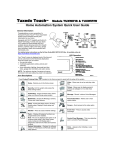
CONTROLLER
General Information
IP Cameras
HOM
E
Satu
03/23/rday
2013
02:5
0PM
Secur
ity
Congratulations on your ownership of a Honeywell
Tuxedo Touch™ Home Automation System which
combines home Security and home Automation.
Equipped with Wi-Fi® capability and built-in Z-Wave®
technology, Tuxedo uses your home Wi-Fi network to
communicate with Wi-Fi enabled devices allowing
control of Z-Wave® devices, (cameras, lights, door
locks, and thermostats, etc.)
Autom
ation
IP:NA
Unkno
wn
MultiM
edia
City
Tem
Humid p
N/A
Wind ity N/A
Cond
N/A
Thermostat
74°
Window Shades
Lamps
Door
Locks
Securi
ty
WPS
Wireles
s LAN
Power
WAN
Internet
Reset
Router
ms_controller-004-V0
LED Operation
Your "Home" screen is displayed most of the time
and can be customized via the Multimedia
Application. From this screen you can control:
• the security system
• multimedia applications (video, pictures and
cameras)
• home automation (lighting, thermostat and door
locks).
NOTE: For optimum viewing of screens and
menus, the device’s font size setting may need to
be adjusted.
SD/SDHC CARD Slot
ARMED (RED) LED
ON – System is armed.
OFF – System is not armed.
READY (GREEN) LED
ON – System is disarmed and ready to arm.
OFF – System is armed or disarmed but not
ready. If disarmed, faults or troubles are present.
MESSAGE (YELLOW) LED
FLASHING – The system contains new
message(s) for the User.
OFF – No new messages.
RESET BUTTON
Press to reset keypad
6280-001-V0
Icon Descriptions
Press the “Product/Training Video” icon
(located on the Home screen) to assist with the setup of the system.
Home - Returns you to the Home screen.
Video - Allows user to set up and play video files.
Security- Arm the system and access the
three arming modes.
Picture - Allows user to display personal photo(s)
as wallpaper or in a slide show format.
Automation - Access Z-Wave setup, Scene
setup, and Room/Group setup screens.
Message - Record / retrieve Voice Messages.
Multimedia - Access the Message, Camera,
Picture and Video features.
Annunciate Status - Allows user to hear system
status.
Setup - Access the Setup menus; IP setup,
System setup, Display & Audio setup and
Account.
Camera – Select to set up and view cameras.
Weather - Select to access weather settings.
Event View – Select to access video recordings.
Panic – Displays Emergency functions (as
programmed by the installer). Note: This icon
is displayed and active on all screens except
while in the Clean Screen mode, during an
LCD Display test in Diagnostics and from the
Video and Camera screens.
Control Panel Message – This icon alerts the
user to a Control Panel Message.
User Setup – Add, Delete, Edit a User
Each user must be assigned a name with a corresponding 4-digit user code in order to gain access to various features and
functions.
Select Setup ˃ System setup ˃ USER SETUP˃ ADD USER.
Select each field and enter the appropriate information; select Save when done.
Follow this procedure for deleting and editing users.
Night Setup - Change arming modes
The NIGHT function can be set to arm the system in one of five arming modes. To change the arming mode, select Setup ˃
System setup ˃ Advanced Setup ˃ Night Setup: choose from:
Away - Stay - Instant (default) - Night (Residential Only) – Maximum.
Arming the System
You can arm the system in one of three arming modes: Away, Stay, and Night.
AWAY – Select to arm when no
one is staying on the premises.
STAY - Select to arm when you are staying home,
but might expect someone to use the entrance door
later.
NIGHT - Select to arm when you are
staying home and do not expect anyone
to use the entrance door.
IMPORTANT: If you return to your home or business and the main burglary sounder is on, DO NOT enter the premises, but call
the police from a nearby safe location. If you return to your home or business after an alarm has occurred and the main sounder
has shut itself off, the controller beeps rapidly upon entering, indicating that an alarm has occurred during your absence. LEAVE
IMMEDIATELY and CONTACT THE POLICE from a nearby safe location.
.
To Arm the System: Select SECURITY
Notes:
1. If Quick Arm is Not enabled in your system, a message to enter your User Code is received.
2. When the system is armed for Stay, Night Stay and Instant mode, Tuxedo beeps 3 times.
3. When the system is armed for Away and Maximum mode, you will hear steady beeps then rapid beeping during the last 10
seconds of Exit Delay.
4. For CP-01 installations, Maximum Mode cannot be used.
To Arm Multiple Partitions: Select SECURITY
˃ Arm Multi-Partition
.
Notes:
1. A user may have access to some or all of the available partitions.
2. If the user code is accepted, the system displays the partitions that the user has access to.
3. If any zones are bypassed, a “Faulted Zones” (
) icon is displayed on this screen.
Disarming the System
To disarm the system when already in the premises select the Disarm icon and enter your 4-digit user code.
To disarm the system when entering the premises enter your 4-digit user code.
To disarm Multi-Partitions - From the Home screen, select the Security, Arm Multi-Partition
icons; enter your 4-digit user code.
and Disarm
Display Faulted Zones / Bypass Zones
How to Display Faulted Zones – Select the SECURITY
˃ FAULTED ZONES
.
˃ MORE CHOICES
˃ SHOW ZONES
.
How to Bypass Zones - Select SECURITY
Notes:
1. Some systems do not allow you to bypass fire, carbon monoxide or emergency zones. On certain fire control systems, a
specified user may be allowed to bypass fire, carbon monoxide and system zones if the user was enabled by your system
installer.
2. Limits apply as to how many zones can be bypassed at one time. These limits are ten zones on residential systems and five
zones on commercial systems.
-2-
Panel Faults
If the following Panel Fault icons are displayed on the Security screen, contract your alarm company.
Panic
AC Loss
Telco-1 Cut
Bell Failure
Pager Failure
Expander Failure
Low Battery
LRR Supervision Failure
Exceeds Max Attempts
Telco-2 Cut
Wireless Failure
Weather Forecast – Set a location
1. Press the Weather feature on the “Home” screen.
2. Select USA/Canada, Zip Code/Postal Code and enter the information on the data entry keyboard; Select OK.
Voice Messages
Select Multimedia
˃ Message
˃ Record
. Record your message (stay within approximately one foot of the
controller) and speak at a normal voice volume. Select Stop
when done. To retrieve a voice message, select from the
message list and then select Play Message
. Select Pause
to pause the playback.
The Message LED will continue to flash until all new messages have been played back.
Multimedia
Using Cameras
1. Select Multimedia
˃ Camera
; images from installed cameras appear.
2. Select Quad View
to view up to four cameras on the same screen. Select a quadrant area on the screen and then select
the camera that you want to appear in that quadrant.
Select Full View
to display a larger view of the image. For pan/tilt style cameras, select Pan/Tilt
to control the camera.
Select Record
to begin a recording, then select Stop
Notes:
1. QuickTime® media player must be installed on your PC.
2. Camera viewing is not compatible w/Opera web browser.
and Auto Pan
to end a recording; a media (SD/SDHC) card is required.
Play Videos: While viewing videos in Full View, press anywhere on the screen to exit.
Select Multimedia
˃ Video
and insert a media (SD/SDHC) card (with stored video files). Maximum video resolution
should not exceed 640 x 480. Highlight a video file from the list and select Play
.
- Select Repeat
to continually replay selected video.
- Deselect Repeat to play the list of video files starting with the first video and ending with the last.
- Use the icons to: Pause
; view a Full View
.
* Note: See the Video Converter document to convert videos for proper playback (provided in the carton).
Customize the Home Screen: While viewing photos in Full View, select anywhere on the screen to exit.
The controller can display personal photo(s) on the Home screen as wallpaper or in a slide show format.
Select Multimedia
˃ Picture
. Insert a media card (SD/SDHC) with up to 1000 stored (.bmp or .jpg) photos.
1. Set up a Slide Show: select a photo from the file list that you want to display and select Add Image
photo you want to add.
• Select the viewing Transition arrow; select Standard, Horizontal, Vertical, and Fade Out.
• Select the Slide Delay arrow to select a time interval for viewing each picture.
-3-
. Repeat this for each
2. Set the background Wallpaper: select a photo from the file list and select Set Wallpaper
Use the icons to: Play Image
˃ view Previous Image
˃ go to Next Image
.
˃ Deselect Image
.
Add Z-Wave Devices
To use Z-Wave devices, they first must be added (“included”) in the system.
Control installed Z-Wave devices such as lights, thermostats door locks, etc., automatically based on scenes you define (see
below). Or, manually control devices from the Device List screen; select Automation
.
Each device must be installed according to the manufacturer’s instructions. Before starting, make sure power switch on devices
are ON, door locks are assembled and have their batteries installed, and thermostats are installed and operating.
1. Select Automation ˃ Z-Wave Setup
˃ Add Device
.
2. At the Z-Wave device, select the Function Key (depending on the device being added).
3. Follow the on-screen messages until “Device added successfully” is displayed.
4. To rename a device, select the device and select Edit Name.
Light, Switch, or Outlet Module / Sensor or Motion Detector Note:
• Make sure power switch on devices are turned ON.
Door Lock Notes:
• Be sure the door lock orientation/handedness is correct.
• Enroll the door lock within 5 feet of the controller.
• Program the selected user code into the door lock. (program the user code in the control panel first).
Thermostat Notes: If not using a Honeywell thermostat, the procedure may vary. Refer to the Thermostat instructions.
• On the Honeywell thermostat select Thermostat; set the “Time/Date” and follow the instructions in the thermostat Installation
Guide for enrollment.
• To complete, select Done. select Exit to return to normal operation.
To verify activation, on the controller, select Back
; wait 30 seconds. Select Refresh
; the new device is displayed.
Create Scenes (define up to 30 scenes)
The Scene feature is used to control a single device, or multiple devices based on pre-set “Conditions,” “Triggers,” and “Actions.”
When a trigger/condition occurs, the defined action is executed. To program a scene:
1. Select Automation ˃ Scene Setup
˃ Add
.
2. Select the Scene Name field; enter a “name” and select OK.
3. Add the “Condition,” “Trigger,” and “Action” that you want to occur (see below). After each selection select Save !!
Note: Determine if you need a Condition. The Condition is a ‘condition’ set to occur prior to a trigger event. See example below.
Example: Turn the lights on when the system disarms, but only at night.
(Condition): “only at Night”
- Set TIME Condition (enter Start Time/ Duration).
(Trigger): when the “system disarms” – Set the trigger to SECURITY: System Disarm.
(Action): Turn the “lights ON” - Set the Action to LIGHT: ON.
Scene Rules
•
•
•
•
•
Triggers and Conditions include: Time setting, Security mode, Thermostat setting, and Door status.
Actions include: Occupancy/Security, Lights On/Off, Thermostat, Door.
Each Trigger event can have up to 3 Actions.
A Trigger event and Condition cannot be the same (i.e., if setting a Trigger event for Occupancy, you cannot set a
Occupancy Condition).
On commercial panels the programming option for “Global Keypad” must be set to “0” for some Scenes to work
properly.
Display & Audio Setup
1. Select Setup; slide the Brightness / Volume bar up or down to change settings. Select Yes to save.
2. Select Disp & Audio
; highlight the field for each option and use the Up/Down arrows to select the desired settings.
- Select Chime, Voice or Voice Chime operating mode (when using Security option only).
- To clean the controller screen, select the Clean Screen icon; select Continue, or select Cancel to exit.
-4-
Language Selection (if applicable)
The controller is defaulted to English. Select the Display and Audio Setup icon and select a Language (English, French Canadian,
Latin American Spanish, or Latin American Portuguese).
Operating Modes
Normal Mode is used when a control panel is connected and provides security functions.
Demo Mode allows the automation and multimedia features to operate in a security mode for demonstration purposes only.
Automation (Occupancy) Mode is used with the Scenes features to automate certain scene actions and allows you to set the
controller in two conditions: Residential and Commercial.
Residential mode (default), the options are: Home, Away, and Night.
In Commercial mode, the options are: Open, Close, and Night.
To select the Operating mode, select Setup
> System setup
> CS Setup
˃ Options
. Highlight the desired
mode check box to enable the option.
To change the occupancy delay time, select a time interval from the Occupancy Delay drop-down list: choose from 15, 30, 60,
120 or 225 seconds.
When done, select Apply
to save the settings.
IP Setup – Set the IP Address
The keypads IP Address is used on a standard web browser to control user functions such as security, Z-Wave operation, and
camera viewing.
Note: Wi-Fi ® has not been evaluated by UL.
1. Select Setup ˃ IP Setup and select a type of network connection: LAN ON or WIFI ON.
For LAN ON (default selection): Connect an Ethernet cable between the router and the controller; the IP address and default
gateway address of the router is displayed.
- If the IP address is not displayed, change the “Internet Connection Type” to Static and manually enter the necessary IP
information from your router onto the controller. Select Save when done.
For WIFI ON: Select WIFI ON and select the desired WIFI router. Enter the Passphrase/Shared Key (if applicable).
- If the WIFI router is not broadcasted, scroll to the bottom of the list and select Add Network; enter your SSID and if
applicable, the Security Mode/Passphrase/Shared Key. Select Save when done.
Notes:
•
Selecting “Save” after changing the port number resets the controller.
•
To view connectivity, select the System Information icon.
•
If left inactive, Web connections disconnect after 10 minutes.
2. Select Account Setup to create a browser log-on page for each user (for higher security) when viewing from a web enabled
device or PC on a different sub-net. Enter the required information for each field; select Save when done.
Secondary Keypad
After all Z-Wave devices have been enrolled into the Primary Keypad (Controller #1), device information can be downloaded to a
Second Keypad (Controller #2). Keep the controllers within 10 feet of each other.
1. On Controller #1: Select Automation ˃ Z-Wave Setup.
2. On Controller #2: Select Z-Wave Primary
. (Lower right side of screen.) Select Yes to change this controller to
Secondary
.
3. On the Primary Controller (#1): Select Add;
4. On the Secondary Controller (#2): Select Add.
How to Send Emergency Messages
An emergency message for fire, panic, or medical can be sent to the central monitoring station from the Emergency screen.
Select the PANIC icon (located in the lower right corner of the screen). Press and hold (for at least 2 seconds) the associated
alarm icon.
FIRE
PANIC
SILENT PANIC
MEDICAL
In Case of Fire Alarm
1.
2.
3.
4.
A FIRE message appears at your controller and remains on until you silence the alarm.
Should you become aware of a fire emergency before your detectors sense the problem, go to your nearest controller and manually
initiate an alarm by pressing the panic key assigned as FIRE emergency (if programmed by the installer) and hold down for at least 2
seconds.
Evacuate all occupants from the premises.
If flames and/or smoke are present, leave the premises and notify your local Fire Department immediately.
-5-
Silencing and Clearing a Fire/Carbon Monoxide Alarm
1.
Silence, acknowledge, and clear the alarm by:
a.
For Residential Systems: Press “Touch here to Silence” on the display to silence the alarm.
For Commercial Systems: Enter your code. This silences and acknowledges the alarm and disarming of the system
(if armed).
b.
For Residential Systems: Select the CLEAR icon followed by your code. This acknowledges the alarm and the
disarming of the system (if armed).
For Commercial Systems: Select the CLEAR icon followed by your code. The system attempts to clear the alarm
from memory. If NOT successful (i.e., smoke in the detector) the Security screen is displayed and the Faulted Zones
icon displays a “Not Ready Fault.”
c.
Select the FAULTED ZONES icon on the Arming screen. The faulted fire/carbon monoxide zone is displayed.
d.
Select the CLEAR icon and then enter your code. This clears the Fire Alarm/CO Alarm from the system.
2.
If the controller does not indicate a READY condition after the second sequence, select the FAULTED ZONES key on the
Arming screen to display the zone(s) that are faulted. Be sure to check that smoke detectors/carbon monoxide detectors are
not responding to smoke, heat, or gas producing objects in their vicinity. In this case, eliminate the source of heat, smoke or
leak.
3.
If this does not remedy the problem, there may still be smoke/gas in the detector. Clear it by fanning the detector for about
30 seconds.
4.
When the problem has been corrected, clear the display by pressing the FAULTED ZONES icon on the Arming screen,
selecting the fire or carbon monoxide zone, selecting the CLEAR icon and then entering your user code.
Note: Contact your Central Station/Security Company for servicing if you have further problems with your system.
Fire and Carbon Monoxide Alarm Operation
Your fire alarm system and carbon monoxide detector (if installed) is on 24 hours a day, providing continuous protection. In the
event of an emergency, the installed smoke, heat, carbon monoxide detectors automatically send signals to your
Control/Communicator, triggering a loud interrupted sound from the controller. An interrupted sound is also produced by optional
exterior sounders. EVACUATE ALL OCCUPANTS FROM THE PREMISES IMMEDIATELY. Notify your Central Station/Security
Company immediately and wait for further instructions.
Routine Care
• Treat the components as you would any other electrical equipment. Do not slam sensor-protected doors or windows.
• Keep dust from accumulating on the keypad and all protective sensors, particularly on motion sensors and smoke detectors.
• The keypad case and sensors should be carefully dusted with a dry soft cloth. Do not spray water or any other fluid on the
units.
Diagnostic Tests / Keypad Reset
There are a total of four diagnostic tests: LCD Display Test, Audio Test, LED Test, and Calibration Test.
From the System setup screen select the Advanced Setup icon and enter your “Authorized Code”.
• Touch the Keypad Reset icon and select OK to reset the keypad.
• Touch the Keypad Test icon and then touch the Test icon associated with the test you wish to perform.
• If the Touch Screen requires recalibration, select the Calibration icon and using a stylus, follow the screen directions by
pressing a series of crosshairs (+) and boxes (❏
❏) on the screen until done.
Notes
Wireless Range
This device complies with the Z-Wave® standard of open-air, line of sight transmission distances of 100 feet. Actual performance in a home
depends on the number of walls between the controller and the destination device, the type of construction and the number of Z-Wave
enabled devices installed in the control network.
Please Note: Z-Wave home control networks are designed to work properly alongside wireless security sensors, Wi-Fi, Bluetooth and other
wireless devices. Some 900MHz wireless devices such as baby cams, wireless video devices and older cordless phones may cause
interference and limit Z-Wave functionality.
Things to consider regarding RF range:
- Each wall or obstacle (such as refrigerator, big screen TV, etc.) between the remote and the destination device will reduce the
maximum range of 100 feet by approximately 25-30%.
- Brick, tile or concrete walls block more of the RF signal than walls made of wooden studs and drywall.
- Wall mounted Z-Wave devices installed in metal junction boxes will suffer a significant loss of range (approximately 20%) since the
metal box blocks a large part of the RF signal.
WARNING: NOT FOR USE WITH MEDICAL OR LIFE SUPPORT EQUIPMENT!
Z-Wave enabled devices should never be used to supply power to, or control the On/Off status or medical and /or life support equipment.
Controlling Devices:
The features and functions that can be controlled vary by manufacturer and you will need to review the user manual that was provided to
determine capabilities of each device.
NOTE: This device is a Security Enabled Z-Wave Controller.
-6-
Z-Wave devices are identified by the Z-Wave logo and can be purchased from your local retailer.
Z-Wave is a registered trademark Sigma Designs, Inc. and/or its subsidiaries.
UL Notes
• Medical functionality has not been evaluated by UL and may not be used in UL Listed applications.
• Web Server/Hosting is not Listed for use in UL installations. Remote arming/disarming/programming is not to be used in UL
Listed Installations.
• Multimedia functionality is supplementary only and has not been evaluated by UL.
• Camera functionality is supplementary only and has not been evaluated by UL.
• Z-Wave applications have not been evaluated by UL.
• Automation functionality is supplementary only and has not been evaluated by UL.
• Access control functionality has not been evaluated by UL and may not be used in UL Listed applications.
• CO annunciation has not been investigated by UL and may not be used for UL installations.
FEDERAL COMMUNICATIONS COMMISSION STATMENTS
The user shall not make any changes or modifications to the equipment unless authorized by the Installation Instructions or User's
Manual. Unauthorized changes or modifications could void the user's authority to operate the equipment.
FCC CLASS B STATEMENT
This equipment has been tested to FCC requirements and has been found acceptable for use. The FCC requires the following
statement for your information:
This equipment generates and uses radio frequency energy and if not installed and used properly, that is, in strict accordance with
the manufacturer's instructions, may cause interference to radio and television reception. It has been type tested and found to
comply with the limits for a Class B computing device in accordance with the specifications in Part 15 of FCC Rules, which are
designed to provide reasonable protection against such interference in a residential installation. However, there is no guarantee
that interference will not occur in a particular installation. If this equipment does cause interference to radio or television reception,
which can be determined by turning the equipment off and on, the user is encouraged to try to correct the interference by one or
more of the following measures:
• If using an indoor antenna, have a quality outdoor antenna installed.
• Reorient the receiving antenna until interference is reduced or eliminated.
• Move the radio or television receiver away from the receiver/control.
• Move the antenna leads away from any wire runs to the receiver/control.
• Plug the receiver/control into a different outlet so that it and the radio or television receiver are on different branch circuits.
• Consult the dealer or an experienced radio/TV technician for help.
INDUSTRY CANADA CLASS B STATEMENT
This Class B digital apparatus complies with Canadian ICES-003.
Cet appareil numérique de la classe B est conforme à la norme NMB-003 du Canada.
FCC / IC STATEMENT
This device complies with Part 15 of the FCC Rules, and RSS 210 of IC. Operation is subject to the following two conditions: (1)
This device may not cause harmful interference (2) This device must accept any interference received, including interference that
may cause undesired operation.
Cet appareil est conforme à la partie 15 des règles de la FCC & de RSS 210 des Industries Canada. Son fonctionnement est
soumis aux conditions suivantes: (1) Cet appareil ne doit pas causer d' interférences nuisibles. (2) Cet appareil doit accepter toute
interférence reçue y compris les interférences causant une réception indésirable.
!
RF EXPOSURE WARNING
Tuxedo must be installed to provide a separation distance of at least 7.8 in. (20 cm) from all persons and must not
be co-located or operating in conjunction with any other antenna or transmitter except in accordance with FCC
multi-transmitter product procedures.
Mise en Garde
Exposition aux Fréquences Radio: L'antenne (s) utilisée pour cet émetteur doit être installée à une distance de
séparation d'au moins 7,8 pouces (20 cm) de toutes les personnes.
-7-
TWO YEAR LIMITED WARRANTY
Honeywell International Inc., acting through its Security & Communications business (“Seller”), 2 Corporate Center Drive, Melville,
New York 11747 warrants its products to be free from defects in materials and workmanship under normal use and service,
normal wear and tear excepted, for 24 months from the manufacture date code; provided, however, that in the event the Buyer
presents a proper invoice relating to the purchased product and such invoice bears a date later than the manufacture date, then
Seller may at its discretion, reflect the warranty period as commencing at invoice date. Except as required by law, this Limited
Warranty is only made to Buyer and may not be transferred to any third party. During the applicable warranty period, Seller will
repair or replace, at its sole option and as the exclusive remedy hereunder, free of charge, any defective products.
Seller shall have no obligation under this Limited Warranty or otherwise if the product:
(i) is improperly installed, applied or maintained;
(ii) installed outside of stated operating parameters, altered or improperly serviced or repaired by anyone other than the
Seller/Seller’s Authorized Service/Repair Center;
(iii) damage is caused by outside natural occurrences, such as lightning, power surges, fire, floods, acts of nature, or the like; or
(iv) defects result from unauthorized modification, misuse, vandalism, alterations of serial numbers, other causes unrelated to
defective materials or workmanship, or failures related to batteries of any type used in connection with the products sold
hereunder.
Exceptions to Warranty With Respect to Honeywell Products listed below:
Hardwire Contacts and PIRs – Seller warrants parts for hardwire contacts and PIRs in accordance with the terms of the above
limited warranty for a period of five (5) years from the manufacture date code.
EXCLUSION OF WARRANTIES, LIMITATION OF LIABILITY
HERE ARE NO WARRANTIES OR CONDITIONS, EXPRESS OR IMPLIED, OF MERCHANTABILITY, OR FITNESS FOR A
PARTICULAR PURPOSE OR OTHERWISE, WHICH EXTEND BEYOND THE DESCRIPTION ON THE FACE HEREOF. TO THE
FULLEST EXTENT PERMITTED BY LAW, IN NO CASE SHALL SELLER BE LIABLE TO ANYONE FOR ANY (i)
CONSEQUENTIAL, INCIDENTAL, INDIRECT, SPECIAL, OR PUNITIVE DAMAGES ARISING OUT OF OR RELATING IN ANY
WAY TO THE PRODUCT AND/OR FOR BREACH OF THIS OR ANY OTHER WARRANTY OR CONDITION, EXPRESS OR
IMPLIED, OR UPON ANY OTHER BASIS OF LIABILITY WHATSOEVER, EVEN IF THE LOSS OR DAMAGE IS CAUSED BY
SELLER’S OWN NEGLIGENCE OR FAULT AND EVEN IF SELLER HAS BEEN ADVISED OF THE POSSIBILITY OF SUCH
LOSSES OR DAMAGES. Any product description (whether in writing or made orally by Seller or Seller’s agents), specifications,
samples, models, bulletin, drawings, diagrams, engineering sheets or similar materials used in connection with the Buyer’s order
are for the sole purpose of identifying the Seller’s products and shall not be construed as an express warranty or condition. Any
suggestions by Seller or Seller’s agents regarding use, applications, or suitability of the products shall not be construed as an
express warranty or condition unless confirmed to be such in writing by Seller. Seller does not represent that the products it sells
may not be compromised or circumvented; that the products will prevent any personal injury or property loss by burglary, robbery,
fire or otherwise, or that the products will in all cases provide adequate warning or protection. Buyer understands that a properly
installed and maintained alarm may only reduce the risk of a burglary, robbery or fire without warning, but it is not insurance or a
guarantee that such will not occur or will not cause or lead to personal injury or property loss. CONSEQUENTLY, SELLER SHALL
HAVE NO LIABILITY FOR ANY PERSONAL INJURY, PROPERTY DAMAGE OR OTHER LOSS BASED ON ANY CLAIM AT ALL
INCLUDING A CLAIM THE PRODUCT FAILED TO GIVE WARNING. However, if Seller is held liable whether directly or indirectly
for any loss or damage with respect to the products it sells, regardless of cause or origin, its maximum liability shall not in any
case exceed the purchase price of the product, which shall be fixed as liquidated damages and not as a penalty, and shall be the
complete and exclusive remedy against the Seller. Should your product become defective during the warranty, please contact
your installer to facilitate repair or replacement with Seller pursuant to the terms hereof. Seller reserves the right to replace any
defective product under warranty with new, refurbished, or remanufactured product.
800- 16582V1_6/14 Rev. B
2 Corporate Center Drive, Suite 100
P.O. Box 9040, Melville, NY 11747
Copyright © 2014 Honeywell International
www.honeywell.com/security