1
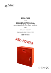
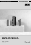
3
Unit design MCH4_A
Size 4
MCH4_A...-503 (400/500 V units): 0370 / 0450
MCH4_A...-203 (230 V units): 0220 / 0300
Figure 6: Unit design, MOVIDRIVE® compact MCH4_A, size 4
05196AXX
1. PE connections
2. X1: Mains connection L1 (1) / L2 (2) / L3 (3)
3. X4: DC link connection -UZ / +UZ
4. PE connections
5. X2: Motor connection U (4) / V (5) / W (6)
6. X3: Braking resistor connection R+ (8) / R- (9)
7. TERMINAL: Option slot for DBG11B keypad or USS21A serial interface
8. V1: Operation LED
9. Retaining screw A for terminal unit
10. X10: Electronics terminal strip, separable
11. X11: Electronics terminal strip, separable
12. X12: Electronics terminal strip, separable
13. Retaining screw B for terminal unit
14. Screw for electronics shield clamp
15. Terminal unit, removable
16. Diagnostic LEDs INTERBUS-FO
17. Only with MCH42A X30...X33: INTERBUS-FO connections
18. X14: Incremental encoder simulation output or external encoder input (15-pin sub D plug)
19. X15: Motor encoder input (15-pin sub D socket)
20. Only with MCH41A X30: PROFIBUS-DP connection (9-pin sub D socket)
MOVIDRIVE® compact MCH4_A Operating Instructions
11