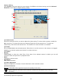
Download DVRPC16T/NVRP4 CMPC Manual

Transcript
CMPC
Central Management System
User Manual
Version 7.3
Oct.2008
DISCLAIMER
No warrant y or repres entation, either express ed or implied, is made wit h respec t to t he
cont ents of thi s document ation, its qualit y, perf ormance, merchant abilit y, or fit ness for a
particular purpose. Inf ormation pres ented in this documentation has been caref ully
checked for reliability; however, no responsibilit y is assumed for inaccuracies. T h e
inform at i on c ontaine d in t his docum ent at ion is s ubject t o c hange wit hout notic e.
In no event will the m anufacturer be liable for direct, indirec t, special, incidental, or
consequential damages arising out of the use or inability to use this product or
docum ent at ion, ev en if adv is ed of t he pos sibilit y of s uc h damages.
TRADEM ARKS
All ot her products or c or porate n am es ment i oned i n this doc um ent ati on are for
identification and explanation purposes only, and m ay be t rademarks or registered
tradem arks of t heir res pec t iv e o wners .
COPYRIGHT
All rights res erv ed. No part of this public ati on ma y be reproduc ed, t ransmit t ed,
transc ribed, st ored in a retrieval s ystem, or translated into any language i n any f orm b y
any m eans wi t hout the writt en perm ission of t he manuf act urer .
TABLE OF CONTENTS
CHAPTER 1
INTRODUCTION ..................................................................................... 1
1.1
Upgrade the BASIC mode to ADVANCED mode...................................................................... 2
1.2
Dual Monitors setting ................................................................................................................ 2
1.2.1
Graphic card with ATi chipset .......................................................................................... 2
1.2.2
Graphic card with NVIDIA chipset ................................................................................... 4
CHAPTER 2
SOFTWARE INSTALLATION.................................................................. 5
2.1
Minimum System Requirements ............................................................................................... 5
2.2
Installing the CMPC Software in Windows XP/2000................................................................. 6
CHAPTER 3
USING THE CMPC.................................................................................. 7
3.1
Running the CMPC Software.................................................................................................... 7
3.2
Using the CMPC Application..................................................................................................... 8
3.3
Using the MiniCenter Viewer .................................................................................................. 10
3.3.1
Remote Bakup............................................................................................................... 12
3.3.1.1
Remote Setup ..................................................................................................... 14
System Setting.......................................................................................................... 14
Camera Setting ......................................................................................................... 16
Record Setting .......................................................................................................... 17
Network Setting ........................................................................................................ 19
Schedule Setting....................................................................................................... 22
Alarm Setting ............................................................................................................ 24
3.3.2
Using the MiniCenter PTZ Camera Controller .............................................................. 28
CHAPTER 4
4.1
System Setting........................................................................................................................ 30
4.1.1
4.2
CUSTOMIZING THE CMPC SYSTEM .................................................. 29
Using System Controller................................................................................................ 33
4.1.1.1
General ............................................................................................................... 33
4.1.1.2
Center Control ..................................................................................................... 34
4.1.1.3
Playback Mode.................................................................................................... 35
4.1.1.4
E-Map Control ..................................................................................................... 37
4.1.1.5
Monitor Control.................................................................................................... 38
4.1.1.6
PTZ Control ......................................................................................................... 39
DVR Setup .............................................................................................................................. 41
4.2.1
To Add and Remove DVR Server.................................................................................. 41
4.3
Camera Setup......................................................................................................................... 42
4.4
Schedule Setup....................................................................................................................... 47
4.4.1
4.5
4.6
Backup Setup.......................................................................................................................... 49
E-MAP Setup .......................................................................................................................... 51
4.6.1
Add a New Map................................................................................................... 52
4.6.1.2
Add a DVR Server............................................................................................... 53
To Use the E-Map.......................................................................................................... 54
Alarm Setting .......................................................................................................................... 55
4.7.1
4.8
To Set Up the E-Map..................................................................................................... 51
4.6.1.1
4.6.2
4.7
To set schedule at a specific portion of time in that hour: ............................................. 48
To setup an alarm condition .......................................................................................... 55
4.7.1.1
To Setup the Call Out List ................................................................................... 56
4.7.1.2
To Setup the Send E-Mail Setting ....................................................................... 57
4.7.1.3
To Set the MMS/SMS Setting.............................................................................. 58
4.7.1.4
Launch program .................................................................................................. 58
4.7.1.5
Popup Video........................................................................................................ 59
User Setting ............................................................................................................................ 61
CHAPTER 5
USING THE PLAYBACK FUNCTION ................................................... 62
5.1
To Playback the video............................................................................................................. 62
5.2
Using the Local Playback Application ..................................................................................... 64
5.3
Using the Download and Playback Application....................................................................... 66
5.4
Using the RealTime Playback Application .............................................................................. 68
5.5
To Cut and Save the Wanted Portion of the Recorded Video................................................. 70
5.6
To Search Using the Visual Search ........................................................................................ 70
5.7
To Search Using the Event Search......................................................................................... 71
5.8
To Search Using the Intelligent Search................................................................................... 72
CHAPTER 6
USING THE EVENT VIEWER ............................................................... 73
Chapter 1 Introduction
CMPC is a central monitoring system that enables user to monitor up to 1000 DVR servers in
advanced mode (see1.1) through an internet connection. Like the DVR program, the CMPC system
also automatically records and displays video when an event has occurred on the remote side of the
DVR server. You can also playback video files locally or download from a remote DVR server.
CMPC
The CMPC system Supports Single, Dual, Triple and Four monitor displays. User can operate the
CMPC system application on different monitors.
1
1.1
Upgrade the BASIC mode to ADVANCED mode
The CMPC has two operating modes – Basic and Advanced mode. In Basic mode, users only can
monitor 16 remote DVR servers. With the Advanced mode, users can monitor up to 1000 remote DVR
servers.
Please follow the below steps to upgrade the CMPC from Basic mode to Advanced mode.
1.
Call your local distributor and purchase a copy of the ADVANCED license or download the BASIC
mode from the Internet.
2.
Your local distributor will then issue you with a Password. (If you have purchased the ADVANCED
mode CD, this password is located on the CD sleeve itself).
3.
The Password is only valid for one time and is tied to the PC hardware. Do not release the
password to any third party.
4.
Run the CMPC program.
5.
Click the exit button 'x' on the upper right corner of the CMPC main screen.
6.
Click About →Register (also see 3.2 # 1)
7.
On the Register dialog box, note down the Activation number. Send both the Activation number
and Password to your distributor.
8.
Your distributor will then issue you with a Serial Key, which is tied to Activation number.
9.
Go back to the Register screen and fill in the serial number from the distributor to upgrade the
CMPC to ADVANCED mode.
The BASIC mode and ADVANCED mode only differs in the number of DVR servers that
can be monitored at the same time. You have the same functionalities on both products.
i
1.2
Dual Monitors setting
Video configuration is different for each different VGA chipsets. Please follow the steps below to
setup the dual monitors display.
1.2.1
Graphic card with ATi chipset
1.
Enter the ATI Catalyst Control Center, user can click the short-cut or right click on the screen.
2.
There are two modes to select ─ Basic and Advanced.
2
3.
If user selected Basic mode, press the Quick Settings tab. Then select the Select a different
desktop mode and click Go.
4.
Select the Extended Desktop and then click Finish.
5.
6.
If user selected the Advanced mode, click the View button.
In Display Manager, right click on the second Display on the right side and select Extend Main
onto monitor.
7.
Adjust each monitor resolution to 1024x768 、1280x1024 ,1920x1200, 1440x900, or 1680x1050.
3
1.2.2
Graphic card with NVIDIA chipset
1.
2.
Click the NVIDIA nView, and select the Dualview mode.
Adjust each monitor resolution to 1024x768 、1280x1024 ,1920x1200, 1440x900, or 1680x1050.
3.
To review if the display mode is correct, you can check the task bar. The task bar will show on the
first monitor only.
Monitor 1
Monitor 2
Manual Conventions
The following conventions are used throughout this manual.
The caution symbol is intended to alert the user of the importance of the particular
installation and operating instructions. Failure to comply may damage the system.
i
The information symbol is intended to provide additional information for the purpose of
clarification.
4
Chapter 2 Software Installation
This chapter describes how to install the CMPC software.
Before installing the software, make sure the Windows OS patches are up to date and the
video graphic card driver is up to date.
i
2.1
To ensure you have the latest copy of the CMPC software, please contact your local
distributor.
Minimum System Requirements
First, must verify if the computer meets the minimum system requirements.

CPU
: Pentium® 4 3.0GHz or above recommended

OS
: Windows 2000 / XP Professional / Vista

RAM
: 512MB for dual display,1GB for Quad display

Hard disk
: 120GB or higher

Media
: CD-ROM drive
VGA
: 32-bit high color SVGA graphics card with 128MB video memory and

DirectDraw® / YUV Rendering Capability

Audio

Internet capacity :10/100 Base-T Ethernet card or Gigabit Ethernet
: Sound card and speakers

























5
2.2
Installing the CMPC Software in Windows XP/2000
1.
Place the installation CD into the CD-ROM drive
then click Install CMPC. And follow the onscreen instructions.
2.
Enter the administrator ID and password.
3.
Click Finish.
4.
User may now run the CMPC program. To run the application, click
or click Start > Programs > CMPC > CMPC .
6
on your PC desktop
Chapter 3 Using the CMPC
3.1
Running the CMPC Software
To run the application, double-click
CMPC.
on your PC desktop or click Start > Programs > CMPC >
For security purposes, some of the features would require you to enter a User ID and Password before
they can be accessed. When the Authorization dialog box appears, key in your User ID and Password.
(If this is the first time, enter the one you have registered when installing the software.)
7
3.2
Using the CMPC Application
When an alarm occurred on the DVR server, the video is transmitted to the CMPC and played on the
CMPC main screen. The transmitted video is approximately 3 seconds long. You may download and
playback the complete video directly from the DVR server by clicking on the event log. Make sure the
main DVR server is set to send video to the CMPC when an alarm has occurred.
The video stream before the eye indicates the latest occurrence. Also, there is a red frame which
indicates the latest occurrence.
(1)
(2)
(3)
(4)
(5)
(6)
(7)
(8)
(9)
(10)
(12)
(11)
Name
Function
(1) Exit
Call up the Logout dialog box.
In the logout dialog box, you may do the following:
- Click Exit to close the CMPC program. Only the administrator is
authorized to access this command.
- Click Login to sign-in as a different user.
- Click Minimize to reduce the CMPC to taskbar button.
Click Cancel to close the Logout dialog box.
8
Name
Function
(1) Exit
Click About to find out more about the software and register the CMPC
application. Click Register to call out the registration window. Enter the
serial number in the Serial number column and click OK to complete the
registration.
- Click Update in Register window to upgrade the newest CMPC application.
For more detail, please contact your local sales dealer.
i
- Once registration is completed, the CMPC application will
upgrade to ADVANCED mode and can monitor up to 1000
DVR servers.
- Without the registration, CMPC application is operating in
BASIC mode and can only monitor 16 DVR servers.
- How to upgrade to ADVANCED mode, please refer to 1.1 .
(2) E-map (F3)
Switch to display the map and show the location of the DVR server on the
map. If you are using a single monitor, press ESC to revert back to the
CMPC main application.
(3) Monitor (F4)
Switch to display live video from the selected DVR servers group. If user is
using a single monitor, press ESC to revert back to the CMPC main
application.
(4) Reset Alarm
Click to reset all DVR alarm status
(5) MiniCenter
Viewer
To call out the MiniCenter viewer. Also, user can double click on screen or
alarm event to call out the MiniCenter Viewer.(Also refer to Chapter 3.3 )
(6) Network
Enable/disable the remote alarm data received. This is activated
automatically when the CMPC software starts up.
(7) Setup
Configure the CMPC system settings. Only the administrator is authorized
to access this command. (see also Chapter 4)
(8) Playback
Select to playback video from the local hard disk or remote DVR server.
(9) Event log
Show a record of activities that has taken place in the system (see also
Chapter 6).
9
Name
Function
(10) Status
Display the current date, and time
(11) Log extender
Expand and reduce the log viewer
(12) Log viewer
List the entire info in event mode or text mode from all DVR servers.
i
3.3
There are a few Hot keys for quick switching between the different applications or display
mode on a single monitor system.
- F1: displays current DVR server information on the CMPC Monitor screen
- F3: Switches to E-Map mode
- F4: Switches to Monitor mode
- Esc: Switches back to the CMPC application main screen
Using the MiniCenter Viewer
(13)
(1)
(2)
(3)
(4)
(12)
(5)
(11)
(10)
(9)
(8)
(7)
(6)
Name
Function
(1) Preview
View live video. User can cancel the connection by clicking Disconnect
button if the connecting time is too long.
(2)
View Alarm
Image
Playback the alarm video clip that is stored on the local hard disk.
(3)
Remote
Playback
Set the amount of time before and after the event to be retrieved from the
DVR server. Click OK to accept and play the retrieved video and Cancel
to void the request (see also Chapter 5.3)
(4) Alarm Info
Display alarm event information which it was defined on DVR server.
User can select priority of alarm event and click Save button to save the
setting.
10
Name
Function
(5) Remote Backup
Remote Backup is purely for backing up the *.dvr file from the DVR
sever(see also Chapter 3.4)
(6) On Screen
Keyboard
If the keyboard is not available, you may use the Virtual Keyboard.
(7) Remote Setup
Change the DVR server settings(see also Chapter 3.5)
(8) Remote I/O
To view sensor and relay, also to turn on/off relay on remote DVR. Select
the relay and right click to turn on /off or trigger the relay.
(9) Remote Control
Connect to the remote DVR server and operate the application. Select
the DVR server from the Name drag down list and click the Remote
Control button. To use this feature, make sure the DVR remote server is
enabled. For more details on software usage, please refer to the DVR
user manual.
(10) Reset Alarm
Clear the DVR server alarm list.
(11) Voice Phone
Enable/disable 2-way audio function. This function allows the CMPC and
DVR server to talk via the internet using a MIC. Make sure your
microphone and speakers work before using this function. If the DVR
server Talk to web-client setting is disabled, you will not be able to hear
from the other side
(12) PTZ Control
Control the PTZ camera (see also Chapter 3.2.2).
(13) DVR Info
Display the DVR information that user has select to preview. User can
switch to view different DVR or camera by drag down the Name or
camera list. Phone, Address, Mobile, Email, and Description information
were defined when set up the DVR server.
11
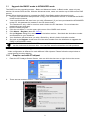
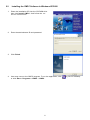
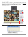
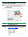
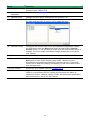
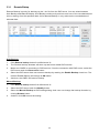
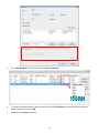
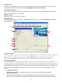
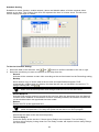
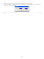
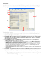
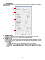
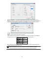
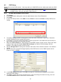
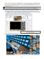
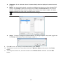
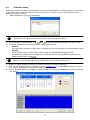
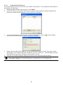
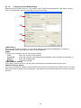
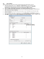
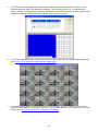
3.3.1
Remote Bakup
Remote Backup is purely for backing up the *.dvr file from the DVR sever. You can select between
Auto Backup and Manual Backup. Auto Backup continuously archives one hour of the recorded data at
a time, starting from the specified date. As for Manual Backup, it only archives the recorded data of
selected date.
Auto Backup:
1.
Click Remote backup button from Minicenter UI.
2.
The Remote backup windows will show up and list all added DVR servers.
3.
Make sure CMPC is connecting to DVR servers. If lost the connection with DVR server, select the
DVR server and click Reconnect button.
4.
Select the DVR server that user wants to backup by marking the Enable Backup check box. The
marked Enable Backup will change to ON status.
5.
And then, the CMPC will start to backup.
Manual Backup:
1.
Click Remote backup button from Minicenter UI.
2.
Select the DVR server and click Modify button.
3.
Select the Manual Backup at DVR setting dialog. And, user can change the backup direction by
clicking Browse button.
4.
And the, click OK to save the setting.
12
5.
6.
The Backup Mode of DVR server will change to Manual.
To execute manual backup, select the file first. Click File Select and select the files that user
wants to backup and click OK.
7.
And then, click Start to backup.
13
3.3.1.1
Remote Setup
Remote Setup is configuring DVR server from remote site.
Click the Remote Setup button to call out the DVR server setup windows.
System Setting
Click Update to accept the new settings, click Exit to exit without saving, and click Default to revert
back to original factory setting.
(6)
(1)
(2)
(7)
(3)
(8)
(9)
(4)
(5)
(1) Delete recorded data after
If you want the system to automatically erase the data after a certain days, enable the Delete
recorded data after check box and enter the numbers of days in Days text box.
(2) Delete event and alarm log after
If you want the system to automatically erase the event and alarm log files after a certain days, enable
the Delete event and alarm log after check box and enter the numbers of days in Days text box.
(3) Video Standard
Change and select the proper video system according to your camera video system. If the video
system setting is wrong, the video would appear abnormal.
(4) Attention Please
Check the attentiveness of the person who is
monitoring the system. You may set the number of
times the Attention dialog box to appear in a day in
Times per day text box.
When this feature is enabled, the Attention dialog box would appear. The person who is monitoring
the system must enter the same number that appears from the left box at the right text box and then
click OK.
14
(5) TV Out
Auto Scan Period: Set the display time gap from 3 to 10 sec. before it switches to the next camera.
(6) Login
Enable the conditions in Login section you want the system to automatically carry out.
- Auto record when login
-
Automatically start video recording when the DVR is executed.
Auto start Network when login
-
Automatically connect to network when the DVR is executed.
Login to compact mode
-
Switch to compact mode directly when the DVR is executed.
Guest Mode
Login to DVR program as guest authority level When the DVR is excuted.
(7) Miscellaneous
Enable the conditions in Miscellaneous section you want the system to perform.
- Beep if no signal
-
Make sound when the video signal is lost.
Mandatory Record
-
Always record video when software is running
Playback Mode
Select the mode of playback the video.

Select date and time: Select the date and time which user wants to playback.

Play the last file: Automatically playback the video from the last hour

Instant Playback: Automatically playback the video which has just recorded
- Date Format
-
Select the date format which wants to display in Select date and time playback mode
Auto Scan Period
Set the time gap of the Auto Scan function from 3 to 10 seconds. This automatically switches to
the next video in cycle depending on the set time gap.
(8) POS
Set from which camera screen to display the data from
the POS equipment. To set the text flow and color
format, click Advanced.
(9) UPS (Uninterruptible Power Supply)
Protect the system from damaging, such as power
surges or brownouts. This automatically gives time to
close the DVR properly when the battery backup power
has reached the Shutdown when capacity below
percentage level setting. The UPS device must be
connected to your DVR.
i
The DVR system default supports SPECO UPS.
15
Camera Setting
Click Update to save and apply the new settings, click Exit to exit without saving, and click Default1/
Default2 to revert back to original factory setting.
(1)
(2)
(3)
(9)
(4)
(5)
(6)
(7)
(8)
(1) Camera Icons
Select the camera number you want to adjust the video setting. To select all the cameras, enable the
ALL check box. To select more than one camera, Right click on the camera icon. To select one
camera only, Left click on the camera icon. The camera icon turns red when it is selected.
(2) Enable
Set to enable/disable the selected camera. When there is no video source on the camera, we suggest
disabling it so that the system won’t detect it as video loss error.
-
-
(3) Camera
Display
Enable/disable to show the video. Even if the video of the selected camera is hidden you can still
record the video and preview it in playback mode.
Name
Change the camera name.
Description
Add a short comment.
(4) Video Adjustment
Adjust the Brightness, Contrast, Hue and Saturation of the selected camera.
(5) Noise Reduction
Reduce undesirable video signal and improve the quality of the video.
i
Noise Reduction uses lots of CPU resource. Please use this feature only if it is really
necessary.
(6) Auto Brightness Control
Automatically adjust the brightness.
16
(7) Night View
Automatically adjust the exposure to make the image more visible especially when the site is dark.
You can only use this function when the Auto Brightness Control is enabled.
(8) Enable Deinterlace
To enhance the video quality. Set the deinterlace mode to #1, if you are capturing motionless picture
and #2, if it captures lots of movement.
(9)Video Screen
Display the video of the selected camera.
Record Setting
Click OK to accept the new settings, click Exit to exit without saving, and click Default to revert back
to original factory setting.
(1)
(2)
(8)
(3)
(4)
(5)
(6)
(9)
(7)
(1) Camera Icons
Select the camera number you want to set the recording setting. To select all the cameras, enable the
ALL check box. To select more than one camera, Right click on the camera icon. To select one
camera only, Left click on the camera icon. The camera icon turns red when it is selected.
(2) Recording Mode
The blocks from 00 to 23 represent the time in 24-hour clock. To record in full 24 hours, select the
recording mode and click the  button. If you want to only record at a particular time, click the colored
block beside the recording mode then click on the time blocks. When the system starts recording a red
triangle mark would appear at the upper left corner of the screen. The recording modes are listed
below:
- Always Recording
-
Record the video from the selected camera and save it to the designated storage path
Motion Recording
Start recording the video from the selected camera only when the system detects movement.
Once a motion is detected, the system automatically saves the previous frames and stop based
17
-
on the Start Record Prior and Stop Record After settings.
Smart Recording
Automatically switch to recorded at the maximum frame rate setting once a motion is detected
and if there is no motion, it records at the minimum frame rate setting. Set the maximum and
-
minimum frame rate setting in (6) Frame Rate section.
No Recording
The system won’t do any recording.
(3) Motion Detection
Adjust the sensitivity of the motion detector. The higher the value, the finer the sensitivity is detected.
When it detects a motion, a green triangle mark would appear at the upper left corner of the screen.
(4) Video Detection
Adjust the intensity of the audio detector. The system detects sound when it exceeds the intensity
value.
(5) Quality
Adjust the video quality. The higher the value, the lower the compression level and uses more hard
disk space.
(6) Frame Rate
Set the maximum number of frames to be recorded during motion and motionless state. The frame
rate ranges from 1 to 30 for NTSC and 1 to 25 for PAL. The higher the frame rate, it uses more hard
disk space.
(7) Video Size
User can activate the Enable Deinterlace to enhance the video quality. Set the Enable Deinterlace
mode to #1, if you are capturing motionless picture and #2, if it captures lots of movement.
(8) Video Screen
Display the video of the selected camera
(9) Compression Type
User can refer the table below to check theDVR supports what type of compression. H264 is the latest
and advanced video compression format that delivers better video quality and smaller file size but this
uses more CPU resource. Advanced MPEG4 and MJPEG, both provide a standard for color picture
compression rate. MPEG4 uses higher compression rate and smaller file size. While MJPEG uses
slightly lower compression rate and bigger file size.
18
Network Setting
Click Update to accept the new settings, click Exit to exit without saving, and click Default to revert
back to original factory setting.
(1)
(7)
(2)
(8)
(3)
(4)
(9)
(5)
(10)
(6)
(1) Server Name
Assign a name for the DVR unit. Letters of the alphabet and numbers only.
(2) Transmitting Cameras
Select and click on the camera number in the Transmitting Camera section you want to make it
accessible via internet using WebViewer, Remote Console, PDAViewer and HandyViewer (still image).
To select all the cameras, enable the ALL check box.
(3) Main Configuration
Set the Server IP and Remote Console Port number. The system will automatically detect your Server
IP address. You need this when accessing DVR server from the remote location via internet.
(4) Dynamic DNS (Domain Name System)
Enter the Domain Name and Password. T To use this feature first registers your domain name on the
following Web site http://speco.dss.com.tw (Default DDNS service port is 53 (upload) /
1053(download))
1. User Login
Browse the website speco.dss.com.tw with Microsoft IE or Netscape Navigator to access
the following dialog.You will be prompted to enter CD key number, product name, password,
and user information. Use this service if the IP address changes each time when you
connect to internet.
19
-
First input CD-Key number (serial number) and select the product name.
-
Then click OK to login or Reset to clear the previous input.
2. User Information
Please provide the following user information, Host Name (user can choose any name
he/she likes except the one violence with other users), Password, E-mail, Company, and
Country. And then, click OK to complete the domain name registration.
(5) Remote Control Server
Enable/disable remote control from remote application (ex. CMPC). Enter the remote accessing port in
Port column.
(6) Network Video Configuration
Set up the video quality and frame rate for viewing and transmitting to the remote program. Scrolling
adjust bar to set the Quality level and FrameRate level.
(7) WebCam Port
Activate Enable Anonymous Login to remotely access the DVR server without the need of password.
The default of WebCam port is 5555.
(8) Voice Phone
Voice Phone is a 2-Way Talk feature that allows the client and server to talk via internet using
microphone. Make sure both microphone and speakers work before using this feature. If the Talk to
Web-Client is disabled, the person in the DVR server side can only hear the voice from the client side
that is when the WebCam 2-Way Talk button is activated. (See also Chapter 7.1 #6). The default port
of voice phone is 5552.
(9) Network Time Synchronization
Adjust the DVR system time same as network time server. Fill in the Time Server IP address or
domain name. Select Automatic Synchronize time to set automatic synchronize time on a daily basis.
20
(10) Other Configuration
-
UPnP
Enable UPnP function to automatically configure the port setting on the local network. This
function is available when there is UPNP device in the same network. It will write the DVR port
information into the router or other network device
-
Enable Original Security Protocol
Enable DVR system to accept the connection from former version of remote access application.
For example, if user uses CMPC version 7.1 and connect to DVR server with version 7.3, and
then, user has to enable this option to make it work. It is due to that DVR system has new
security protocol and it’s not compatible with old remote software.
-
Enable White List
An access permit list for the remote accessing of DVR server. Enter the IP address and click
Add. Or, enter a range of IP address and click Add. To delete the IP from the list, select the IP
and click Delete button. To reset the input, click Clear button.
-
Enable HandyViewer
Enable remote users to use a PDA or a mobile phone to access DVR server and select the
video size and quality. (See also Chapter 7.5 and 7.6)
-
Network Bandwidth Limit
By Channel: Set the network bandwidth by each channel.
All: Set the total network bandwidth consumption limit.
21
Schedule Setting
Schedule to record, backup, enable network, reboot and disable alarm of all the cameras either
weekly or one time. The number from 00 to 23 represent the time in 24-hour clock. The left most
column display the days in a week.
To Set the Schedule Setting:
1.
2.
Select the date in the calendar. Use
and
buttons to shift the calendar to the left or right.
Select the condition you want to schedule in the drop down list.
Record
Activate all the cameras to start video recording at the set time based on the Recording setting
Backup
Save another copy of all the data at the set time and specified backup path. DVR
automatically updates and only backup the data that are not yet included in the archive. To
assign backup path, click
.
i
-
-
Enable Network
Activate DVR remote system to access at the set time. After the appointed time, the Network
function will be disabled. If the Network function is already enabled, the Network function will
not be disabled when the appointed time has ended.
Reboot
Restart the PC at the appointed time.
i
-
Make sure the backup folder and storage folder are not on the same drive.
Make sure the Windows operating system is set NOT to require you to login user
name and password. This way the system will be able to run DVR program.
Disable Alarm
Deactivate the alarm at the set time temporarily.
Turn on Relay #
Active the Relay at the set time. If there are no Relays are connected, Turn on Relay #
function will not display in drag down list. The Relay number will depend on how many Relays
are connected.
22
3.
4.
Specify to either schedule it weekly or one time. Click  to make a selection.
Click on the blocks to set the schedule. Or click All to select all. To store the setting, click Save. To
remove the settings, click Clear.
5.
To end Schedule Setting, click OK to exit and accept the setting and Cancel to exit without saving
the setting.
23
Alarm Setting
click Add to insert and set new alarm setting, click Delete to remove the selected alarm setting, click
OK to exit and save the setting, Cancel to exit without saving, and Default to revert back to original
factory setting.
(1)
(2)
(3)
(7)
(4)
(5)
(6)
To set the Alarm Setting:
1.
Click Add to insert and set a new alarm setting. Click the items in the (7) Alarm Setting List, if
you want to modify the alarm setting.
2. In (1) Alarm Setting number/Name/Description, display the selected alarm setting number in the
list below. Enter alarm name and description.
3. In (2) Enable Time, the number from 00 to 23 represent the time in 24-hour clock. Select the time
and click the block you want to activate or deactivate the alarm function. When it is deactivated
the color of the block turns white.
4. In (3) Conditions, you can set “Trigger if any” to activate if it falls to one of the conditions or
“Trigger if all” to activate if it falls to all conditions.
- In Camera section, select and click on the camera number (01 to 16) in Motion Detected and
Video Loss to set the condition for the system to alarm.
- In Missing and Suspicious Object Detected, click the camera number (01 to 16) and select
the certain object on the screen (right click on camera number for detailed setting)), and when
the certain object is missing or doubtful, the system will alarm. In Scene Change, when the
camera has been moved, the system will alarm, too.
- In Voice Detection, click the camera number (01 to 16) to the system to alarm when detect the
abnormal voice.
5. In (4) Sensor, select and click on the sensor number (use  and  to select the sensor) to set the
condition for the system to alarm. If the sensor normal status is high, set the sensor condition to
low .
- Enable/disable the Abnormal Event check box, to set the condition of the event for system to
alarm.
•
Normal Reboot: when the DVR system reboot without abnormal condition, the system will
send out the alarm message.
24
•
•
•
•
•
•
Abnormal Reboot: when the DVR system reboot in irregular condition, the system will
send out the alarm message.
Recording is switched off: when the recording has been stopped, the system will send
out the alarm message.
Network is switched off: when the network connection of DVR system is lost, the system
will send out the alarm message.
Hard Disk failed: when the hard disk can’t work normally, the system will send out the
alarm message.
Temperature: set a temperature limited of system for system to alarm. When DVR system
temperature is over the temperature limited, the system will send out the alarm.
Illegal Entry: any objects move between selected regions which user has set up in
Object Counting section, the system will send out the alarm. Select the entry (object
moves from region 1 to 2 or from region 2 to 1) and camera for system alarm detection.
-
6.
7.
Enable/disable the POS Keyword check box, to scan the data from the POS if it matches the
keyword.
- Enable/disable the Alarm Message check box, to active with external alarm message by your
own program. For the detail configuration, please contact the local reseller.
- Enable/disable the Alarm Button check box, to active manual alarm function. To define alarm
message of manually alarm trigger. Click alarm button and select the alarm button # and fill in
the description of alarm button.
In (5) Alarm Reset, click the camera number (use  and  to select the alarm) to set the reset
condition of alarm. Once alarm is reset, all alarm action will stop at the moment. If the sensor
normal status is high, set the sensor condition to low.
In (6) Action, you may now set the alarm action for the system to perform when the alarm
condition is activated.
- Launch E-Map
Display mini Emap screen.
- TV Out
Switch to only display the video on TV from where the alarm is activated.
a. Select the camera from drop down list to specify which camera video to be displayed on
TV when the alarm is triggered.
i.
Alarm Camera: when a channel has an alarm occurred, and then, the channel video
that has an alarm occurred will be displayed on TV.
ii.
Camera #(1~32): select the camera channel video that wants to be displayed on TV
when an alarm is activated.
b. Retrieve time: set the waiting duration before system switching back to original display
mode on TV automatically. If the retrieve time is un-mark, the alarm video will keep
displaying until user switch back to normal display mode manually. The retrieve time range
25
-
-
is 3~ 600 seconds.
Enlarge Camera View
Switch to only display video in Preview/Advanced mode from where the alarm is activated.
a. Select the camera from drop down list to specify which camera video to be enlarged on
screen when the alarm is triggered.
iii.
Alarm Camera: when a channel has an alarm occurred, and then, the channel video
that has an alarm occurred will be enlarged on screen.
iv.
Camera # (1~32): the selected channel video that will be enlarged on screen when
an alarm is activated.
b. Retrieve time: set the waiting duration before system switching back to original Preview
mode. If the retrieve time is un-mark, the alarm video will keep enlarging until user switch
back to Preview mode manually. The retrieve time range is 3~ 600 seconds.
Send E-mail
Send an electronic text message.
Beside the Send Email check box, click Detail. In the E-mail Setting dialog box, click OK to exit
and save the setting and Cancel to exit without saving the setting.
(1) Mail Server
Enter the SMTP Server and port. If your e-mail system requires user identification, enable
Authentication check box and enter User ID and Password.
(2) Mail
To check if it is working, click Test Account button.
From: Enter the sender e-mail address.
To and CC: Enter the recipient email address and separate it with comma or a semicolon
(;).
Subject: Enter the message title.
Message: Type the message.
(3) Email Notice Setting
–
Notice Interval: Set the period of time before it sends another e-mail notice.
–
Embedded image
: Select the image size and set the number of frames.
–
Attach image when sensor is triggered: When the sensor is triggered, the system
will capture the image and send the image to the certain e-mail address with the alarm
message.
(4) Modem Dial up Setting
User may set the time to disconnect automatically, just enable the Auto Disconnect after
check box and set time.
(1)
(2)
(3)
(4)
26
-
File Transmission via FTP
Upload file to remote computer thru FTP (File Transfer Protocol).
1.
Beside the File Transmission via FTP check box, click Detail.
2.
In the FTP Setting dialog box, enter the FTP IP, port, user ID and password.
3.
Click OK to exit and save the setting and Cancel to exit without saving the setting.
-
Start Recording
Record the video from the selected camera.
1.
Beside the Start Recording check box, click Detail.
2.
In the Alarm Recording Setting dialog box, select the camera to enable/disable video
recording. Enable All to select all cameras.
3.
In the Frame Rate selection, select As Setting to record the number of frames based on
the Recording Setting or Max to record the maximum of frames based on the available
speed.
4.
In the Stop Recording after text box, set the number in second for the program to
continue recording after the alarm has ended.
5.
Click OK to accept the new settings and Cancel to exit without saving.
-
Alarm SOP (Standard Operation Procedure)
List the instructions to inform the person of what to do when the alarm is activated.
Beside the Alarm SOP check box, click Detail. In the step text boxes, type the standard
protocol when the alarm is activated. When the alarm is activated, the Standard Operation
Procedure dialog box will appear. Just click Next to see the next instruction, Back to see the
previous instruction, Finish to end and Abort to terminate.
27
-
Send to CMPC (Central Management System)
Enable/disable the selected camera to send video to CMPC when the alarm is activated.
Beside the Send to CMPC check box, click Detail. In the CMPC Setting, select the camera to
enable/disable sending the video to CMPC. Enable All to select all cameras. Then, click OK to
accept the new settings and Cancel to exit without saving.
3.3.2
Using the MiniCenter PTZ Camera Controller
(3)
(2)
(1)
(4)
(5)
Name
Function
(1) AutoPan
Operate the PTZ cameras automatically based on the selected camera
group preset position number.
(2) Focus +/-
Adjust the focus manually to produce clearer image.
(3) Zoom +/-
Zoom in and out the image.
(4) Direction
buttons
Adjust and position the focal point of the PTZ camera.
(5) Camera preset
position number
Move the PTZ camera to the preset point.
28
Chapter 4 Customizing the CMPC System
In the CMPC application, click the
button to customize the CMPC system. In the
Authorization dialog box, enter the administrator User ID and Password.
When the CMPC configuration setup selection appears, select and click the buttons you want to
change the setting.
29
4.1
System Setting
In the System Setting dialog box, click OK to accept and start to reload the new setting, and Cancel to
exit without saving.
(1)
(2)
(3)
(4)
(5)
(6)
(7)
(8)
(1)
(2)
Alarm Network Port
Select a port for receiving alarm video from DVR server. Any network service port can be
assigned as long as the port doesn’t conflict with current network service.
Alarm Record Path
By default, the alarm folder is automatically generated to where the CMPC application is installed
and for saving the alarm clip videos and log files. The suggested hard disk capacity for storing the
alarm video is 30GB.
1.
Click Setup.
2.
In the Authorization dialog box, enter the administrator User ID and Password.
3.
Click System >
. In the Browse For Folder dialog box, locate where you want to store
the alarm video clip. Click Make New Folder to create new folder, OK to accept and Cancel
to exit.
30
4.
The text below the Alarm Record path text box shows the hard disk free space and total
space in parenthesis.
5.
(3)
(4)
In the System Setting dialog box, click OK to start reloading the new setting and Cancel to
exit without saving the new setting.
Language
Customize the system to display the tool tips and dialogs based on the selected language. By
default the set language is in English.
1.
Click Setup.
2.
In the Authorization dialog box, enter the administrator User ID and Password.
3.
Click System.
4.
In the Language drop down list, click and select the language.
Miscellaneous
 Date Format - Select from different date formats
1.
Click Setup.
2.
In the Authorization dialog box, enter the administrator User ID and Password.
3.
Click System.
4.
In the Date Format drop down list, click and select the style.
5.
In the System Setting dialog box, click OK to accept the new setting and Cancel to exit
without saving the new setting.
 Display position – To decide the Center, Emap, Monitor, or Playback to be displayed on
which screen. CMPC system supports up to 4 monitors, users are allowed to customize
the display position of different monitoring tool. Click Detail to select the display screen
setting. The new screen display setting will be effect at next time login.
31











System Controller – To configure the parameters that is for communicating with the
System Controller (an optional accessory). Also please refer to Using System Controller or
user manual of the System Controller. Click Setting to configure system controller.
Enable – Mark the check box to enable the System Controller function.
Model – Select model of the System Controller.
Port – Select the com port that is connected with the System Controller. Click Setup to
configure com port value. The com port value is shown in below table:
Baud rate
9600
Data bits
8
Parity
No
Stop bit
1
Flow control
No
ID – Set an ID for DVR server (0~99). This ID is a key for communicating between the
System Controller and the DVR server.
i
When the DVR server ID is X, the DVR server can be controlled by System
Controller irrespective of the DVR ID that is selected in System Controller.
32
4.1.1
Using System Controller
4.1.1.1
General
Function
Description
/ ESC
Exit the current mode.
RECORD
RECORD
Switch control to monitor screen. Press
4 /
)
EMAP
Switch control to E-map screen
NETWORK
Switch control to Center screen
PREVIEW
Switch to view Monitor screens
PLAYBACK
To call out Playback application
1 /
Number button 1
2 /
Number button 2
3 /
Number button 3
4 /
Number button 4
5 /
Number button 5
6 /
Number button 6
7 /
Number button 7
8
Number button 8
9
Number button 9
33
1 /
+ screen number (
~
Function
Description
0
Number Button 0
ENTER
An enter key for confirming a action
4.1.1.2
Center Control
Function
Description
EMAP
Switch control to E-map screen
PREVIEW
Switch to view Monitor screens
To reset alarm status
PLAYBACK
To call out Playback application
1 /
Keyboard Number button 1
2 /
Keyboard Number button 2
3 /
Keyboard Number button 3
4 /
Keyboard Number button 4
5 /
Keyboard Number button 5
6/
Keyboard Number button 6
7 /
Keyboard Number button 7
8
Keyboard Number button 8
9
Keyboard Number button 9
0
Keyboard Number button 0
34
Function
Description
ENTER
An enter key for confirming a action
4.1.1.3
Playback Mode
Function
Description
UP


 DOWN


 LEFT /


 RIGHT
Go up to the selection ( DVR server, playback mode,
playback time and playback date)
Go to previous frame while playback
Go down to the selection ( DVR server, playback mode,
playback time and playback date)
Go to next frame while playback
Use to select the playback time and date
Wind back the recorded video file while playback
Use to select the playback time and date
Play the recorded video file at the speed of 2x, 4x, 8x, 16x
or 32x
Turn Right: Play the record video file at the fast speed
Turn Left: Play the recorded video file at the speed of 1/2X, 1/4X, or 1/8X
/ ESC
Move to the beginning of the recorded video file
/ TAB
Wind back the recorded video file
/
.
Play the recorded video file
/
Pause playing the recorded video file
/
Go to the end of the recorded video file in Playback mode
ENTER
An enter key for confirming a action
1 /
channel 1
Switch to a 1 channel view mode
2 /
channel 2
Switch to a 4-split screen mode
3 /
channel 3
Switch to a 9-split screen mode
35
Function
Description
4 /
channel 4
Switch to a 16-split screen mode
5 /
channel 5
Switch to a 8-split screen mode
6 /
channel 6
Switch to a 13-split screen mode
7 /
channel 7
Switch to a 32-split screen mode
8
channel 8
9
Channel 9
0
Number Button 0
-
i
-
To select the channel 1~9, press 0 + channel number (1~9) or press channel
(1~9) and wait about 1 second.
To select channel 10~32, Press 2 digital channel numbers. For example:
channel 10, press 1 + 0.
FN
-
To switch to split screen mode, please press
to enter function mode first.
/
Capture and save the screen shot either in *.jpg or *.bmp format in
Playback mode
/
Select the date on the calendar and the time from 00 to 23 to where to
start playing the recorded video file in Playback.
Move Joystick to left and right to select day and up and down to select
hour.
/ A-B
Keep a portion of the recorded video in Playback mode
/
Save the segmented file in *.mpg, *.avi, or *.dvr format in Playback mode
Exit from Playback application
36
4.1.1.4
E-Map Control
Description
Function
To exit from E-Map screen / DVR watch window
Back up last level of E-Map
1 /
Channel 1 in DVR watch
2 /
Channel 2 in DVR watch
3 /
Channel 3 in DVR watch
4 /
Channel 4 in DVR watch
5 /
Channel 5 in DVR watch
6 /
Channel 6 in DVR watch
7 /
Channel 7 in DVR watch
8
Channel 8 in DVR watch
9
Channel 9 in DVR watch
0
Number Button 0
i
-
To select the channel 1~9, press 0 + channel number (1~9) or press channel
(1~9) and wait about 1 second.
To select channel 10~32, Press 2 digital channel numbers. For example:
channel 10, press 1 + 0.
/ ESC
-
Press
(ESC) to back to split mode from single channel view mode.
To select different DVR server on the E-map to
view or select next level of E-map to view.
 Left /  Right
UP /  DOWN
ENTER
To confirm the selection, press
(enter)
button, and then, the DVR watch window will
show up or the next E-map will show up.
37
4.1.1.5
Monitor Control
Function
Description
To exit from Monitor screen
1 /
Channel 1
2 /
Channel 2
3 /
Channel 3
4 /
Channel 4
5 /
Channel 5
6 /
Channel 6
7 /
Channel 7
8
Channel 8
9
Channel 9
0
Number Button 0
-
i
-
To select the channel 1~9, press 0 + channel number (1~9) or press channel
(1~9) and wait about 1 second.
To select channel 10~32, Press 2 digital channel numbers. For example:
channel 10, press 1 + 0.
/ ESC
-
/ TAB
Press
(ESC) to back to split mode from single channel view mode.
/ TAB
+ 3 digital numbers can switch to different monitor set. CMPC
/ TAB
system can support 128 monitor set. User can press
+ monitor set
number (001 ~ 128), and then, the monitor screen will show the entered
monitor set.
38
4.1.1.6
PTZ Control
Function
Description
/
Adjust the focus in manually
/
To speed up the movement of camera
/ A-B
Adjust the focus out manually
/
To speed down the movement of camera
Move to PTZ preset position
i
- Move to PTZ preset position 1~9, press
+ number button (1~9) and wait
about 1 second.
-
Move to PTZ preset position 10~16, Press
example: preset position number 10, press
- Please press
+ 2 digital numbers button. For
+ 1 + 0.
button each time before press PTZ preset position number
button.
1 /
Keyboard Number button 1
2 /
Keyboard Number button 2
3 /
Keyboard Number button 3
4 /
Keyboard Number button 4
5 /
Keyboard Number button 5
6/
Keyboard Number button 6
7 /
Keyboard Number button 7
8
Keyboard Number button 8
39
Function
Description
9
Keyboard Number button 9
0
Keyboard Number button 0
UP /  DOWN
Tilt up and down
 LEFT /  RIGHT
Pan left and right
Turn Right: Zoom in the image
Turn Left: Zoom out the image
(5)
(6)
(7)
(8)
Configuration
Import / Export the CMPC system configuration
Attention Please
Check the attentiveness of the person who is monitoring the system. You may set the number of
times the Attention dialog box to appear in a day in Times per day text box. To check the graph
on how fast the person response, click Analysis. When this feature is enabled, the Attention
dialog box would appear. The person who is monitoring the system must enter the same number
that appears from the left box at the right text box and then click OK.
Alarm Video
Set up the video transition when alarm occurs.
- One frame: a single video frame will be transmitted when alarm occurs.
- Pre/Post Event Time: Set the video duration before and after the event to send
Monitor Text Setting
Enable/disable the camera information display and display position on the monitor screen.
40
4.2
DVR Setup
Display the list of all DVR servers. User may add up to 1000 DVR servers, delete and modify the DVR
setting.
- In ADVANCED mode, user can add up to 1000 DVR servers(see 1.1)
- In BASIC mode, user only can add 16 DVR servers
i
4.2.1
To Add and Remove DVR Server
1.
2.
3.
4.
Click Setup.
In the Authorization dialog box, enter the administrator User ID and Password.
Click DVR.
In the DVR Setup section, click Add to insert, Delete to remove and Edit to modify DVR server
setting.
5.
To continue adding a DVR, in the text box, enter the name, IP/Domain, Login User, Password,
Confirm Password of the remote DVR server.
If necessary, fill up the contact information to let the personnel in the CMPC side know whom to
get in touch with when an event has occurred.
Select the Video Quality for video display on the CMPC system monitor screen. When the video
quality is high, user can enable Show POS message box and the POS message will also
display on the CMPC system monitor screen.
Set the Storage Path for saving the recorded video data of the selected cameras on the Monitor
screen.
Set the max video recorded storage capacity of this DVR server on the CMPC system server.
Enter the value in Quota.
6.
7.
8.
9.
10. In the DVR Setting dialog box, click OK to accept the new setting and Cancel to exit without
saving the new setting.
11. The CMPC system will connect to DVR server. If the connecting time takes too long, user can
click Disconnect button to cancel the connect action.
41
4.3
Camera Setup
Select the camera from different DVR servers in order to monitor on same screen. The selected
cameras will be played on Monitor screen (see 3.2 # 2).
1.
2.
3.
4.
Click Setup.
In the Authorization dialog box, enter the administrator User ID and Password.
Click Camera.
Click Add to create a monitor set. Enter a name in Name column (12 characters only). To record
the cameras video, mark the Record box. Otherwise, the cameras video will not be saved on the
CMPC system hard disk. Mark the Enable IP camera direct connection that CMPC will receive
the camera video direct from IP camera which will reduce the loading of DVR server. User can
set the camera transmitting Frame Rate, but the real transmitting frame rate depends on camera
setting. Click OK to save the setting.
i
5.
6.
7.
CMPC only supports two monitor set recording.
After the Monitor set has been created, select the DVR server. And then the camera channels of
the DVR server will display on the Camera Select window. User can combines different cameras
from different DVR servers as a monitor set. And all camera channels can be selected by
different Monitor set raptly.
User can depend on the monitor size to select the screen type – 4:3 (regular screen monitor) or
16:10 (width screen monitor). The 4:3 and 16:10 screen type support different monitor layout.
Select the camera that user wants to add, and then click Add button. The selected camera
channel will be added to Monitor Layout window. User can add up to 64 cameras in 4:3 screen
type and 80 cameras in 16:10 screen type. To remove the camera from the Monitor Layout
42
window, select the camera and click Delete button. To delete all cameras, click Clear All button.
User can enter a description for a channel. Click a camera in Monitor Layout window and enter
the description in Camera Description. The camera description will display on the channel of
the monitor screen.
i
8.
User can drag the camera channel to Monitor Layout window without using Add button.
In Monitor Layout window, user also can set the channel for specific type functions instead of
added camera channels from DVR servers. In Monitor Layout window, select one of blank
channel (NONE) and click the radio button of type (Hotspot, Sequence, Matrix, Image, or None).

Hotspot: To set the channel for displaying selected camera channel video. User can clickand-drag to select multiple channels as a hotspot channel area.
Drag to select the multiple blank channels
as a hotspot channel
In the Monitor screen, user can use right muse button to drag the one camera channel to the
hotspot channel for enlarge viewing.
NV6E[Cam12]
NV77[Cam01]
NV77[Cam02]
NV77[Cam03]
NV77[Cam04]
NV77[Cam05]
43
NV77[Cam06]
NV77[Cam07]
NV60[Cam01]
NV60[ Cam02]
NV60[Cam03]
NV60[Cam04]
NV60[ Cam05]
NV60[Cam06]
NV60[Cam07]
NV60[ Cam08]
NV60[Cam09]
NV6E[Cam01]
NV6E[Cam02]
NV6E[Cam03]
NV6E[Cam04]
NV6E[Cam05]
NV6E[Cam06]
NV6E[Cam07]
NV6E [Cam08]
NV6E[Cam09]
NV6E[Cam10]
NV6E[Cam11]
NV6E[Cam12]
NV77[Cam08]
NV77[ Cam09]
NV77[Cam10]
 Sequence: Set the selected channel to automatically switch to display all camera channels
in cycle.
 Matrix: set the selected channel to receive and display the alarm event from selected DVR
 servers. Click Setup to select the DVR servers. Enable the Retrieve time to set a period
time (0 ~ 255 sec) for alarm event to display. If the retrieve time doesn’t enable, the alarm
 event will display on screen until next alarm event come in.














i
On the DVR site, user need to enable and configure the matrix to send to CMPC.
 Image: To insert an image on selected channel. The image supports *.bmp and *.jpg format.
Click Setup and browse where the image located is.
9.
Click OK to save the setup. To exit without saving, click Cancel.
10. To delete the monitor set, select the monitor set in Monitor Select windows and click Delete
button.
11. To modify the monitor set, select the monitor set in Monitor Select windows and click Edit
button.
44
Press F1 to display channel information
Clcik to enable audio
Name of monitor set displayed
Switch to center monitor
Clcik to select different
Monitor set to view
12. To viewer different monitor set, click Monitor Selector and click-and-drag the monitor set to the
monitor and press Refresh button.
To unselected monitor set,
click the mouse right button
to unselect the monitor set.
1
Click-and-drag the monitor set
to monitor for viewing.
2
Click Refresh button to switch
to new selected monitor set
13. Also, user can call up the PTZ camera control panel by click PTZ icon. The PTZ icon will be
available when there are PTZ cameras in Monitor set.
45
Clcik to enable PTZ control panel
14. In Monitor screen, user can click a channel to view in full screen. Press Esc to back to multiple
channel screen.
46
4.4
Schedule Setup
Schedule to record, backup, enable network, reboot and disable alarm of all the cameras either weekly
or one time. The number from 00 to 23 represent the time in 24-hour clock. The left most column
display the days in a week.
1.
Select the Monitor group for scheduling.
i
2.
3.
The Monitor set can be scheduled only when the recoding is enabling.
Select the date in the calendar. Use
and
buttons to shift the calendar to the left or right.
Select the condition you want to schedule in the drop down list.
Record
Activate all the cameras to start video recording at the set time based on the Recording setting
Backup
Save another copy of all the data at the set time and specified backup path. DVR
automatically updates and only backup the data that are not yet included in the archive. To
assign backup path, click
.
i
4.
5.
6.
Make sure the backup folder and storage folder are not on the same drive.
Specify to either schedule it weekly or one time. Click  to make a selection.
Click on the blocks to set the schedule (see also Chapter 4.4.1). Or click All to select all. To store
the setting, click Save. To remove the settings, click Clear.
To end Schedule Setting, click OK to exit and accept the setting and Cancel to exit without saving
the setting.
47
4.4.1
1.
2.
3.
To set schedule at a specific portion of time in that hour:
Right click the colored blocks.
In the Select time dialog box, click to enable or disable
the portion you want to set.
Click OK to accept the setting and Cancel to exit
without saving the setting.
48
4.5
Backup Setup
In the Backup Setting dialog box, the number from 00 to 23 represent the time in 24-hour clock. The
numbers from 01 to 16 represent the camera number.
1.
Select the DVR that wants to backup
2.
Select the date of the recorded file in the calendar you want to backup. Use
and
buttons to
shift the calendar to the left or right.
In the table below, click on the blue block to select the recorded file or click camera (01~16) or
time (00~23) to select the whole row or column. The blue block turns red when it is selected. The
block that appears in white doesn’t have data. If you want to set the specific time, right-click on the
selected block. Then, set the time to start and end.
Check the information beside the calendar.
3.
4.
Selected Files : Show the number of files selected.
Require Space : Show the total size of the selected file.
5.
6.
Enable Auto partition and select to divide the file size into DVD-R or CD-R. DVR automatically
backup and divide the file sizes to facilitate burning into DVD or CD disc.
Enable Include player when backup that will included a Qplayer program for playback backup
file in backup folder when backup. Only administrator user has the authority to enable or disable
this function.
49
7.
If you do NOT want to keep the recorded file in the storage folder, enable Delete files after
Backup check box.
8. Click
to set the path on where to store the backup file.
9. Click
to start archiving the selected file.
10. In the Processing… dialog box, to stop archiving press Abort. When done, in the Backup Path list,
shows the archived item. To burn the file in CD, you need to have NERO 6 or above installed in
your PC then select the item in the list and click Burn. Click Exit to end this procedure and burn it
later.
11. In CD/DVD Backup, enable/disable Delete file after burning check box to remove the archived file
after burning. Click Burn to start and Exit to cancel this process.
50
4.6
E-MAP Setup
Holds up to 64 maps in *.bmp/*.jpg format. The map is hierarchy in structure and users can add a map
on another map. User also may add the DVR icons on the map.
4.6.1
To Set Up the E-Map
1.
2.
Click Setup.
In the Authorization dialog box, enter the administrator User ID and Password.
3.
4.
Click E-Map.
The E-Map interface will show up in assigned monitor if user is using multiple monitors for the
CMPC system. If user is using single monitor for the CMPC application, the E-Map interface will
show up in front of the CMPC application interface. Press Esc or click Center button to switch
back to CMPC application interface or press F3 to switch to E-Map interface again.
On the E-Map interface:
(1) go back to previous layer of map
(2) Show the current name and layer of map
(3) Load a map to replace the current map
(4) Add a new map. The new map is added on the current map as a next level.(See 4.4.1.1)
(5) Display the selected Map or DVR server information.
(6) Add a DVR server icon on the map. (See 4.4.1.2)
(7) Click OK to save the setting and exit the E-Map interface.
(8) Click Cancel without saving the setting and exit the E-Map interface.
5.
(1)
(2)
(3)
(4)
(5)
51
(6)
(7)
(8)
4.6.1.1
Add a New Map
1.
2.
3.
4.
Click
button
In the Authorization dialog box, enter the administrator User ID and Password
Click E-Map button
Click Add Map button and the Map setting window will show up.
5.
Give a name for the new map.
6.
Click
to locate the map file. In the open dialog box, locate and select the map and click
Open
7.
User may now drag and move the Map icon to its place on the map.
8.
User can double click the Map icon to view the map.
9.
To edit and delete the map, click the map icon and Edit and Delete button will appear on the
Map interface. Click Edit to modify the map (see 4.4.1.1 # 5~6). To delete the map, click the map
icon and click Delete button.
10. Click OK to accept the new setting and Cancel to exit without saving the new setting.
- User can add up to a total of 64 maps
- User also can right click the mouse button on the map, a function list window will show
up. User can select the function to add and modify the map.
i
52
4.6.1.2
Add a DVR Server
1.
2.
3.
4.
5.
Click
button
In the Authorization dialog box, enter the administrator User ID and Password
Click E-Map button
Click Add DVR button and the Add DVR window will show up.
Select the DVR server from the Add DVR window and click OK.
6.
7.
User may now drag and move the DVR icon to its place on the map.
To edit and delete the DVR server on the map, click the DVR server icon and the Edit and
Delete buttons will appear on the Map interface. Click Edit to modify the DVR server (see 4.2.1 #
5~10). To delete the DVR server from the map, click the DVR server icon and click Delete.
Click OK to accept the new setting and Cancel to exit without saving the new setting.
8.
i
User also can select the DVR icon and right click the mouse button on the map, a function
list window will show up. User can select the function to add, edit, and delete DVR, edit
map, reset Alarm, and view and control remote I/O devices status.
53
4.6.2
To Use the E-Map
When the alarm has been activated, the DVR icon blinks and turns red.
1.
On the CMPC main application, click E-map or press F3.
2.
Click the DVR server icon and a DVR watch window will show up and connect the DVR server to
play the live video.
To stop the DVR server icon from blinking, right click the mouse button and select Reset Alarm
or Reset Alarm (all). The DVR server icon will stop blinking.
To switch back to the main application, press ESC.
3.
4.
5.
To setup the E-Map, click
button or right click the mouse button and select E-Map setup
and the E-Map interface will switch to the E-Map setup mode. (see 4.4.1)
i
-
6.
If user uses dual monitor, the E-map setup mode is active in E-Map windows and the
E-map setup mode will not enable to active in CMPC main screen.
To switch back the setup mode in CMPC main application, click OK or Cancel to exit
the setup mode in E-Map interface.
User can click the Map icon on the map to view the map. And the map can be added map on
map and up to 64 maps. (see 4.4.1.1).
54
4.7
Alarm Setting
In the Alarm Setting dialog box, just select and enable the condition for the system to alarm and the
action for the system to perform when an alarm is activated. User can setup a total of 16 different
combinations of alarm settings. Each alarm setting can apply to several DVR servers. Click OK to
accept new setting and Cancel to exit without saving.
4.7.1
To setup an alarm condition
1.
2.
3.
4.
Click the Add button to add a new alarm condition.
Give the name of this alarm condition.
Fill the simply description of this alarm condition in Description column.
Apply to the DVR server, click Select DVR. In Select DVR window, select the DVR server and
click Add. To exit and save the setup, click OK.
5.
6.
Select the Conditions.
Select the Action.(see 4.5.1.1 & 4.5.1.2 & 4.5.1.3 & 4.5.1.4 & 4.5.1.5)
7.
Click OK to save the setting. To cancel click Cancel.
55
4.7.1.1
To Setup the Call Out List
To use this feature, the PC must have a voice modem connected to it. The supported audio system is
only 8KHz and 16Bit mono.
1.
Beside the Make Phone Calls check box, click Detail.
2.
In the Call Out List, click Add to insert a new contact number, Modify to edit the selected item,
Remove to delete the selected item, Test to check if it is working.
3.
In the Call Out Setting, enter the phone number and description. Click
recorded sound and Record to make a new voice message.
4.
When the Sound Recorder appears, use the record control panel to record, stop, play, rewind
and forward. If you want to keep the existing file, click File > Save As…, enter filename and click
Save. Make sure you have microphone connected to your PC.
Click OK to exit and accept the setting and Cancel to exit without saving the setting.
5.
i
to select existing
To use make phone call function, please make sure you deselect the option "wait for dial
tone before dialing" in modem properties in control panel of your Windows OS.
56
4.7.1.2
To Setup the Send E-Mail Setting
Beside the Send Email check box, click Detail. In the E-mail Setting dialog box, click OK to exit and
save the setting and Cancel to exit without saving the setting.
(1)
(2)
(3)
(4)
(1)Mail Server
Enter the SMTP Server and port. If your e-mail system requires user identification, enable the
Authentication check box and enter User ID and Password.
(2)Mail
To check if it is working, click the Test Account button.
From:
Enter the sender e-mail address.
To and CC:
Enter the recipient email address and separate it with comma or a semicolon (;).
Subject:
Enter the message title.
Message:
Type the message.
(3)Email Notice Setting
In the Notice Interval text box, set the period of time before it sends another e-mail notice.
(4)Modem Dial up Setting
If you are using dial up modem, enable Auto Dial up check box and select the modem name. You may
also set the time to disconnect automatically, just enable the Auto Disconnect after check box and set
the time.
57
4.7.1.3
To Set the MMS/SMS Setting
To use this feature, GSM/GPRS modem is required. Connect the GSM/GPRS modem to the serial
COMM port of PC. Beside the SMS/MMS check box, click Detail.
Select the port number in ComPort drop down list from where the GSM/GPRS modem is
connected.
Click Enter Pincode button to fill in pin code of your mobile phone if your mobile system require
verifying pin code for SMS/MMS sending.
1.
2.
i
3.
4.
5.
6.
The incorrect pin code will lock your mobile phone.
In Phone Num text box, enter the contact number.
You may now set to send thru SMS &/or MMS. If you enable SMS setting, just enter the
message in the Message Text box. Click SMS Test to verify the SMS setup is available.
If you enable MMS, enter the Loing account, Password, APN name, WAP IP, MMS address,
subject of MMS message and the message. User can Import the previous MMS setting or
Export the current MMS setting. If you are not sure, please contact your mobile service provider.
To verify the setting, click MMS Test.
Click OK to accept the new settings and Cancel to exit without saving.
4.7.1.4
Launch program
To call up the external program that is provided by a 3rd party. Click Detail and click
to locate the
program path. Enable the Multiple instance check box if the external application has been
programmed to execute repeatedly.
58
4.7.1.5
Popup Video
The Popup video will co-work with alarm condition of Receive Alarm. When user selects the alarm
condition of Receive Alarm, and then the action of Popup video will be un-gray and available for select.
The popup video will show up 4 windows at once.
On the upper right corner of popup video windows, there two figures that are to represent nailed
popup video windows and mini center function.
(a)
(b)
(c)
(a)To call out DVR watch window. The DVR watch window will display the DVR all channels’ video
image.
59
CAM 01
CAM 02
CAM 03
CAM 04
CAM 05
CAM 06
CAM 07
CAM 08
CAM 09
(b) To nail popup video window for avoiding new coming alarm video to replace it.
(c) To call out MiniCenter(also see Chapter 3.3)
To Setup Popup Video:
1.
Click Detail to call up Alarm Display Selection windows.
2.
Select the type of popup video
Static View: The DVR server only transmits one frame of video and popup on CMPC
site.
Live View: The DVR server will continue to transmit video to CMPC site while popup
video window is open.
3.
To close popup video windows, just click “X” of windows.
60
4.8
User Setting
CMPC supports 256 user account that includes operator and administrator account.
1.
Select the Authorization Level – Operator or Administrator. User can define each
operator/administrator account’s authority of DVR server and Monitor set. Only the
administrator is authorized to close and customize the CMPC system.
2.
Enter the Name, Description, Password, and Confirm password of the account.
3.
Select the DVR servers that allow this account user to preview and playback. The DVR server
with check mark means is selected.
4.
Select the Monitor set that allow this account user to view. The Monitor set with check mark
means is selected.
5.
User can assign a valid date for Operator user. Select Being Date and End Date to assign a
valid date for operator account. The account only will be available during the assigned date.
6.
Click OK to accept the new settings and Cancel to exit without saving.
Click to select
61
Chapter 5 Using the Playback Function
User can choose to playback video stored on the local hard disk or download the video from the
remote side of the DVR server.
5.1
To Playback the video
1.
2.
Click
In the DVR Playback select window, select DVR server to play video from the remote DVR
server.
3.
For Local Playback, user can select to preview 16 channels at a time. Only the cameras
previously selected in Monitor and with the Record button enabled /recorded can be recorded.
In the Video Playback Date/Time Selection, the numbers from 00 to 23 represent the time in 24hour. The numbers from 01 to 16 represent the camera number. The blue block indicates that
there is a recorded video file in that period of time. While the red bar indicates the selected
recorded video for viewing (see also 5.2 Using the Local Playback Application).
4.
You can select Local Playback, Download and playback or RealTime playback. Click OK to
proceed and Cancel to void this operation.
62
5.
For Download and Playback, the numbers from 00 to 23 represent the time in 24-hour in the
Remote Playback Date/Time Selection windows. The numbers from 01 to 16 represent the
camera number. The blue block indicates that there is a recorded video file on that period of time.
While the red block indicates the selected recorded video for viewing.
6.
In the Time Selection screen, click on the video thumbnail you want to download and open (see
also 5.3 Using the Download and Playback Application).
7.
For RealTime Playback, the number from 00 to 23 represent the time in 24-hour clock in the
Video Playback Date/Time Selection windows. The numbers from 01 to 16 represent the camera
number.(see 5.4 Using the RealTime Playabck Application)
63
5.2
Using the Local Playback Application
(14)
(13)
(12)
(11)
(10)
(9)
(8)
(7)
(1)
(2)
(3)
(5)
(4)
(6)
Name
Function
(1) Split Screen
Mode
Select from six (6) different split screen types to playback the recorded video
file of all the cameras, or one camera over the other or alongside on a single
screen.
i
- If there are only 4 cameras, you won’t be able to switch to 9, 16, and 13 split screen
mode.
- To zoom into an area on the screen, Right click and Drag a square on the area you
want to enlarge.
- To view 32 channels, click 16 split screen mode button to view 16 channels each time.
Check the camera ID icon to know which channels are displaying now.
(2) Exit
Close the Player.
(3) Progress bar
Show the progress of the file being played. You may move the bar to seek at
64
Name
Function
any location of the track.
(4) Hour Buttons
Select and click to playback the recorded video file on the specific time
frame.
(5) Playback
Control
Buttons
Begin: Move to the beginning of the recorded video file.
Previous: Go back to the previous frame.
Slower: Play the recorded video file at the speed of 1/2x, 1/4x, or
1/8x.
Rewind: Wind back the recorded video file.
Pause: Briefly stop playing the recorded video file.
Play: Play the recorded video file.
Faster: Play the recorded video file at the speed of 2x, 4x, or 8x, 16x, 32x.
Next: Go to the next frame.
End: Go to the end of the recorded video file.
(6) Date
Select the date on the calendar and the time from 00 to 23 to where to start
playing the recorded video file.
i
The numbers from 00 to 23 represent the time in 24-hour clock. The numbers from 01 to
16 represent the camera ID. The blue colored column indicates that there is a recorded
video file on that period of time. While the red colored column indicates on where to start
playing the recorded video file.
(7) Status bar
Display the recorded date, time and play speed.
(8) Camera ID
Show the number of cameras that are being viewed. When you are in single
screen mode, click the camera ID number to switch and view other camera.
(9) Segment
Keep a portion of the recorded video you want (see also 5.5).
(10) Full screen
View in Playback-compact mode. To return, Right click the mouse or press
ESC on the keyboard.
When you switch to full screen in multiple-screen mode, Left click to toggle
to only display one of the video in the multiple-screen mode or all.
(11) Visual
Search
Search from a specific camera by Date, Hour, Minute, 10 Seconds and
Second (See also 5.6).
(12) Find Next
Search for the next event or changes in the motion detector frame. You can
use this when you are using Intelligent Search or Event Search only.
(13) Event
Search
Search from the recorded activities that take place in the system (i.e.,
Sensor, Motion, Video Loss, POS) (See also 5.7).
(14) Intelligent
Search
Search the changes in the motion detector frame (See also 5.8).
65
5.3
Using the Download and Playback Application
(12)
(11)
(10)
(9)
(8)
(7)
(6)
(5)
(4)
(1)
(2)
(3)
Name
Function
(1) Exit
Close the player
(2) Progress
bar
Show the progress of the file being played. You may move the bar to seek at
any location of the track.
(3) Date
Open other file.
(4) Playback
Control
Buttons
Begin: Move to the beginning of the recorded video file.
Previous: Go back to the previous frame.
Slower: Play the recorded video file at the speed of 1/2x, 1/4x, or
1/8x.
Rewind: Wind back the recorded video file.
Pause: Briefly stop playing the recorded video file.
Play: Play the recorded video file.
Faster: Play the recorded video file at the speed of 2x, 4x, 8x, 16x or 32x.
Next: Go to the next frame.
End: Go to the end of the recorded video file.
(5) Camera ID
Show the number of cameras that are being viewed. When you are
in single screen mode, click the camera ID number to switch and
view other camera.
(6) Export
Export includes Snapshot, Print, Output Video Clip, and Backup function.
Snapshot: Capture and save the screen shot either in *.jpg or *.bmp
format.
Print: Print the screen shot.
Output Video Clip: Save the segmented file in *.mpg, *.avi, or *.dvr format
(see also 5.5).
(7) Segment
Keep a portion of the recorded video you want. You may follow the
instruction in 5.5.
(8) Full screen
View in Playback-compact mode. To return, press the right button of the
mouse or ESC on the keyboard.
When you switch to full screen in multiple-screen mode, Left click to toggle
to only display one of the video in the multiple-screen mode or all.
66
Name
Function
(9) Visual
Search
Search from a specific camera by Date, Hour, Minute, 10 Seconds and
Second. (See also 5.6)
(10) Find Next
Search for the next event or changes in the motion detector frame. You can
use this when you are using Intelligent Search or Event Search function.
(11) Event
Search
Search from the recorded activities that take place in the system (i.e.,
Sensor, Motion, Video Loss, POS) (See also 5.7).
(12) Intelligent
Search
Search the changes in the motion detector frame (See also 5.8).
67
5.4
Using the RealTime Playback Application
(9)
(8)
(7)
(1)
(6)
(2)
(3)
(4)
(5)
Name
Function
(1) Split Screen
Mode
Select from two (6) different split screen type to playback the recorded
video file of all the camera, or one camera.
i
- If there are only 4 cameras, you won’t be able to switch to 9, 16, and 13 split screen
mode.
- To zoom in an area on the screen, Right click and Drag a square on the area you
want to enlarge.
(2) Exit
Close the player
(3) Progress bar
Show the progress of the file being played. You may move the bar to seek
at any location of the track.
(4) Hour Buttons
Select and click to playback the recorded video file on the specific time
frame.
i
The Hour buttons represent the time in 24-hour clock. The blue bar on top of the hour
button indicates that there is a recorded video file on that period of time. While the red
bar indicates that you are currently viewing the recorded video file.
(5) Playback
Control Buttons
Begin: Move at the beginning of the recorded video file.
Previous: Go back to the previous frame.
Slower: Play the recorded video file at the speed of 1/2x, 1/4x, or
1/8x.
Rewind: Wind back the recorded video file.
Pause: Briefly stop playing the recorded video file.
Play: Play the recorded video file.
Faster: Play the recorded video file at the speed of 2x, 4x, or 8x, 16x or
32x.
Next: Go to the next frame.
End: Go to the end of the recorded video file.
68
Name
Function
(6) Date
Select the date on the calendar and the time from 00 to 23 to where to
start playing the recorded video file.
i
The numbers from 00 to 23 represent the time in 24-hour clock. The numbers from 01 to
16 represent the camera ID. The blue colored column indicates that there is a recorded
video file on that period of time. While the red colored column indicates on where to
start playing the recorded video file.
(7) Camera ID
Show the number of cameras that are being viewed. When you are in
single screen mode, click the camera ID number to switch and view other
camera.
(8) Export
Snapshot: Capture and save the screen shot either in *.jpg or *.bmp
format.
(9) Full screen
View in Playback-compact mode. To return, press the right button of the
mouse or ESC on the keyboard.
When you switch to full screen in multiple-screen mode, Left click to
toggle to only display one of the video in the multiple-screen mode or all.
69
5.5
To Cut and Save the Wanted Portion of the Recorded Video
1.
Use the Playback Control buttons or drag the bar on the playback progress bar and pause on
where you want to start the cut. Then, click Segment to set the begin mark.
2.
Use the Playback Control buttons or drag the bar on the playback progress bar and pause on
where you want to end the cut. Then, click Segment to set the end mark. To cancel segmentation
or set the segment marks from the start, click Segment button again.
3.
4.
Click Output button to save the wanted clip.
In the Save As dialog box, locate on where you want to save the file, type the filename, and select
the video format.
5.6
To Search Using the Visual Search
1.
2.
Click Visual Search.
In the Visual Search Setting dialog box, select the Camera number and the date. Then click OK.
3.
When a series of frames appear by date, click on the frame to display another series of frames
and search by every Hour of that date, every Minute of that hour, every 10 Seconds of that minute,
every Second of that 10 seconds. To go back, click
. To view from the selected frame and
close event search, click
.
70
5.7
To Search Using the Event Search
1.
2.
Click on the video screen on where you want to search.
Click Event Search. The Event Search text (red) would appear at the lower left corner of the
screen.
3.
In the Event Search Setting dialog box, check the type of condition you want to search. If you
select POS, in the Find Text box, type the word. Then, click OK to start searching. The video
search would stop at the frame that matches the condition. To keep on searching, click
.
You may also set to search and list all the result. Just check the Output Event List box. In the
Search Duration section, set the Begin Time, End Time and Searching Interval. Then, click OK
to start searching.
When the Event list appears, click and select the item you want to view.
4.
5.
71
5.8
1.
2.
3.
4.
To Search Using the Intelligent Search
Click on the video screen on where you want to search.
Click Intelligent Search. The Intelligent Search text (red) would appear at the lower left corner of
the screen.
When the Intelligent Search Setting dialog box and motion detector frame appear, you may adjust
the sensitivity bar and the motion detector frame size and location. To set motion detector frame
size and location, left click and drag on the screen. Then, click OK to start searching. The video
search would stop at the frame that matches the condition. To keep on searching, click
.
You may also set to search and list all the result. Just check the List box. In the Search Duration
section, set the Begin Time, End Time and Searching Interval. Then, click OK to start searching.
72
Chapter 6 Using the Event Viewer
Show the record of activities that take place in the system. To filter the records, select and click the
option button to only display Alarm, Motion, DVR Reboot, HDD fail, Login DVR, Connection Success,
Connection Loss, Reset Alarm, DVR Exit, Login DVR or All Event. Click Refresh to update the list and
Export to output the event search result in *.excel format.
To view image logs, click Image Log button. The image log windows will display. Double click on the
image log to view more details.
73