1
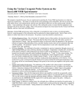
AN2142
Application note
ST10F27X firmware development
getting started with tasking ST10 toolchain
Introduction
This document provides an introduction to the Tasking toolchain (version v8.5 r1) for the ST10F27x
product family. It describes the software environment required to develop an ST10F27x application and
summarizes the different steps needed to configure the Tasking development toolset, to build and to
debug an application on the target hardware.
Two software examples are supplied with this application note. The first one is a small application
demonstrating an input / output toggling function. The required steps to create the project, build and
debug it will be described. The second one illustrates another example using interrupts. Both examples
are loaded and executed from an external RAM using Tasking RAM monitor.
The application source files are provided within an archived file. This file must be unpacked into a
directory before use.
June 2006
Rev 1
1/16
http:/www.st.com
www.BDTIC.com/ST
16
AN2142
Contents
1
Tasking ST10 toolchain . . . . . . . . . . . . . . . . . . . . . . . . . . . . . . . . . . . . . . . . . 3
1.1
Starting Tasking development environment (EDE) . . . . . . . . . . . . . . . . . . . . . 3
1.2
Creating a new project . . . . . . . . . . . . . . . . . . . . . . . . . . . . . . . . . . . . . . . . . . 4
1.3
Adding files to the project . . . . . . . . . . . . . . . . . . . . . . . . . . . . . . . . . . . . . . . . 6
1.3.1
Adding existing files . . . . . . . . . . . . . . . . . . . . . . . . . . . . . . . . . . . . . . . . . . . . . 6
1.3.2
Adding new files . . . . . . . . . . . . . . . . . . . . . . . . . . . . . . . . . . . . . . . . . . . . . . . 7
1.4
Setting build options . . . . . . . . . . . . . . . . . . . . . . . . . . . . . . . . . . . . . . . . . . . . 8
1.5
Building the application . . . . . . . . . . . . . . . . . . . . . . . . . . . . . . . . . . . . . . . . 11
1.6
Using the RAM Monitor to debug the application with Cross View debugger 12
2
Application example: interrupt handling . . . . . . . . . . . . . . . . . . . . . . . . . . 14
3
Revision history . . . . . . . . . . . . . . . . . . . . . . . . . . . . . . . . . . . . . . . . . . . . . . 15
2/16
www.BDTIC.com/ST
AN2142
1
Tasking ST10 toolchain
Tasking ST10 toolchain
The TASKING Embedded Development Environment EDE can be divided into three main parts:
●
Edit / Project management: In this part, projects are created and maintained, project
source files are edited etc.
●
Build: Here, a makefile (created by the Edit part) is used to invoke the needed toolchain
components, resulting in an absolute object file(*.abs).
●
Debug: In this part, the absolute file is used to debug the project.
The figure below shows how these parts interface with each other and enumerates the most
imporant generated files.
Project management
Tool options
*.C
*.asm
EDIT part
makefile
*.src
*.obj
*.out
*.map
etc...
*.sre
(Motorola S record format)
*.abs
Debugger
BUILD part
*HEX
DEBUG part
Neither the toolset installation nor the license management are described in this application
note. This section assumes that Tasking is already installed on the development host.
For more details on Tasking installation and license management, refer to Tasking
documentation.
This section describes the steps required for creating, building and debugging an ST10F27x
application using the tasking toolchain.
1.1
Starting Tasking development environment (EDE)
Getting started with EDE:
●
Select Start -> Programs ->Tasking C166-ST10 from the Windows Start menu.
●
Select C166-ST10 EDE from the menu
3/16
www.BDTIC.com/ST
AN2142
Tasking ST10 toolchain
Tasking starts and the following window appears:
Files Window
Project Window
Output Window
The files window is used to edit source files. The project window contains several tabs for
viewing information about projects and other files. Finally, the output window contains several
tabs to display results of EDE operations such as compiles and builds.
For further information about the window’s contents, refer to the Tasking documentation.
1.2
Creating a new project
When you use EDE, you need to setup a project space and add a project to it. A project space
stores a set of projects. It allows multiple projects to be displayed at a time and allows the user
to organize projects.
A project space file has the extension ‘*.psp’. A project file has the extension ‘*.pjt’.
The following steps describe how to create a new project:
●
Select New project space from the File menu. A Create a New Project Space dialog box
is displayed (see the figure below)
●
Use the Browse button to select a working directory.
●
Enter ’Getting Started Examples’ as the project space name in the Filename field.
●
Click OK to confirm your entries and close the Create a New Project Space window.
4/16
www.BDTIC.com/ST
AN2142
Tasking ST10 toolchain
The following window appears:
●
●
●
Click on ’Getting Started Examples’ and choose Add New Project
An Add New Project to Project Space dialog box is displayed (see the figure below)
Use the Browse button to select a working directory.
5/16
www.BDTIC.com/ST
AN2142
Tasking ST10 toolchain
1.3
●
Enter ’ST10F27x_port2_pins_toggling’ as the project space name in the Filename field.
●
Click OK to confirm your entries and close the Add New Project to Project Space
window
Adding files to the project
Now, we need to add some source files to the project. This can be done in two ways, either the
source file already exists in the working directory (proceed as described in Section 1.3.1) or
you add new source files and enter your own code (as described in Section 1.3.2).
1.3.1
Adding existing files
●
Copy in your working directory the ‘main.c’ file located in the folder ‘Example1’ provided
with this application note.
●
Right-click on ’ST10F27x_port2_pins_toggling’ and choose Add Existing Files ->
Browse.
The following window appears:
●
Choose ‘main.c’ and Click Open to confirm
6/16
www.BDTIC.com/ST
AN2142
1.3.2
Tasking ST10 toolchain
Adding new files
●
Right-click on ’ST10F27x_port2_pins_toggling’ and choose Add New File
●
An Add New File to Project dialog box is displayed (see the figure below)
●
Use the Browse button to select a working directory.
●
Enter ’main.c’ as file name in the Filename field.
7/16
www.BDTIC.com/ST
AN2142
Tasking ST10 toolchain
●
Click OK to confirm your entries and close the Add New File to Project window.
In this project, there is only one source file. If the application requires more than one source file
and header files, you have to include them in the project in the same way as ‘main.c ‘ file.
1.4
Setting build options
Before building your project, you should specify compiler and linker options. This section will
present the most important options that must be set.
●
Select Project Options from the Project menu. The Project Options dialog appears. This
dialog contains several entries where you can specify processor and development tool
options.
●
In the left pane expand the Application entry and select Processor
●
Precise STMicroelectronics as Manufacturer and select ST10F27x as processor. Let’s
choose ST10F276 for the example.
8/16
www.BDTIC.com/ST
AN2142
Tasking ST10 toolchain
●
Now, you have to define the memory mapping. For this purpose, select
Project Options -> Linker/Locator -> Memory
●
Fill in the table using the ST10F276 datasheet , the Memory Areas part.
●
Select the memory model. For this purpose, select
Project Options -> Application -> Memory Model
9/16
www.BDTIC.com/ST
AN2142
Tasking ST10 toolchain
The following window appears:
There are 5 memory models: Tiny, Small, Medium, Large and Huge. The small memory model
is used by default.
The memory model defines the default variable and function location and their default pointer
size. The right selection depends on the application and impacts the compiler efficiency.
The memory models with their characteristics are represented in the following table:
Data size
Code size
Far/Huge/Shuge
data allowed
Near data
allowed
Tiny
<64K
<64K
No
Not applicable
Small
<64K
>64K
Yes
Not applicable
Medium
>64K
<64K
Yes
Yes
Large
>64K
>64K
Yes
Yes
Huge
>64K
>64K
Yes
Yes
For more details about memory models and choice criteria, please refer to Tasking
documentation.
10/16
www.BDTIC.com/ST
AN2142
1.5
Tasking ST10 toolchain
●
If you want to generate HEX or Motorla S formats, select
Project Options -> Linker/Locator -> Output Format -> Intel HEX Records
(or Motorola S records).
●
Hardware configuration: before building the application and starting CrossView, the board
configuration must be selected in the dialog 'EDE -> Project Options -> CrossView Pro ->
Execution environment". Also, the check box "Use Simulator" must be disabled in this
dialog.
When using one of the default board configurations, there is no need to change the startup
registers like SYSCON. With a user-defined configuration, many more settings and startup
registers must be initialized, also in the cfg file. Please refer to the cfg file(s) belonging to
the default boards for more information.
Building the application
The project has been configured. You can now build it. Select Build from the Build menu. If
there are no errors, a file.abs will be generated in order to debug the application.
When building the application successfully, many files will be generated automatically (as
described at the beginning of this document) and placed in the working directory.
11/16
www.BDTIC.com/ST
AN2142
Tasking ST10 toolchain
1.6
Using the RAM Monitor to debug the application with Cross
View debugger
Cross View debugger provides a high level interface between the user and a program running
in the target system (execution environment).
Cross View debugger runs on a PC computer and is connected to the ST10F27x target
microcontroller via an RS232 interface.
The connection to the target and the debug of the application require that you have successfully
compiled and built your application.
The monitor requires an external RAM memory to run. This RAM memory must be selected at
reset.
●
External RAM Chip select should be active
●
Make sure that ROMEN bit in SYSCON register is cleared (Internal ROM is disabled)
●
Enter the bootstrap loader mode by forcing P0L.4 to 0 at reset
12/16
www.BDTIC.com/ST
AN2142
Tasking ST10 toolchain
●
Select Debug from the Build menu. The Cross View debugger window appears:
Run Icon
Run Step by Step icon
Source Window
Breakpoint
Register Window
Cross View
Command Window
Memory Window
●
Once the ‘st10f27x_port2_pins_toggling.abs’ file has been loaded on the target, you can
debug it. To execute the application, Select Run from the Run menu of the Cross View
window.
You can use breakpoints, a simple double click on a line sets a breakpoint on that location.You
can also run the application step by step. You can display memory and register contents. Select
View -> Register from the Cross View window to display the Register pane or View -> Memory
from the Cross View window to display the Memory pane. By means of these panes, you can
view and set the content of a register and a memory location.
For more details on CrossView debugging features, refer to the Cross View Debugger
documentation.
13/16
www.BDTIC.com/ST
Application example: interrupt handling
2
AN2142
Application example: interrupt handling
This section describes a simple ST10F27x software example making use of the interrupts. The
application uses Timers’ overflow interrupts to generate two square signals with different
frequencies on two standard port pins: P2.0 & P2.1.
The project contains 3 source files:
●
Timer.c: It contains c source code for the following project routines
–
Configure_GPT1_Timer_2(): In this routine, GPT1 Timer 2 is set up to operate in
Timer mode and is configured to generate an interrupt every 1.678 seconds.
–
Configure_GPT1_Timer_3(): In this routine, GPT1 Timer 3 is set up to operate in
Timer mode and is configured to generate an interrupt every 104.8 milliseconds.
–
Timer 2 and Timer 3 interrupts’ definitions: Timer 2 interrupt is toggling P2.0 while
Timer 3 interrupt is toggling P2.1.
●
Timer.h: It contains Timer.c routines prototypes.
●
main.c: It uses the routines described in Timer.c in order to start the two timer overflow
interrupts.
Timings suppose that the chip is operating at a frequency of 40 Mhz.
Both hardware and software environments have been setup as described in the first chapter.
The figure below shows the behaviour of the port 2 pins 0 and 1 and the GPT1 Timer 2 & Timer
3 overflow interrupts.
PIN P2.0 OUTPUT (GPT1 TIMER 2 OVERFLOW INTERRUPT)
PIN P2.1 OUTPUT (GPT1 TIMER 3 OVERFLOW INTERRUPT)
The example source code is located in the ’..\Example2’ directory.
For more details about the timers’ functionalities, their registers and interrupts’ handling, refer to
the ST10F27x user’s manual.
14/16
www.BDTIC.com/ST
AN2142
Revision history
3
Revision history
Table 1.
Document revision history
Date
Revision
30-Jun-2006
1
Changes
Initial release.
15/16
www.BDTIC.com/ST
AN2142
Revision history
Please Read Carefully:
Information in this document is provided solely in connection with ST products. STMicroelectronics NV and its subsidiaries (“ST”) reserve the right to make changes, corrections,
modifications or improvements, to this document, and the products and services described herein at any time, without notice.
All ST products are sold pursuant to ST’s terms and conditions of sale.
Purchasers are solely responsible for the choice, selection and use of the ST products and services described herein, and ST assumes no liability whatsoever relating to the
choice, selection or use of the ST products and services described herein.
No license, express or implied, by estoppel or otherwise, to any intellectual property rights is granted under this document. If any part of this document refers to any third party
products or services it shall not be deemed a license grant by ST for the use of such third party products or services, or any intellectual property contained therein or considered
as a warranty covering the use in any manner whatsoever of such third party products or services or any intellectual property contained therein.
UNLESS OTHERWISE SET FORTH IN ST’S TERMS AND CONDITIONS OF SALE ST DISCLAIMS ANY EXPRESS OR IMPLIED WARRANTY WITH RESPECT TO THE
USE AND/OR SALE OF ST PRODUCTS INCLUDING WITHOUT LIMITATION IMPLIED WARRANTIES OF MERCHANTABILITY, FITNESS FOR A PARTICULAR
PURPOSE (AND THEIR EQUIVALENTS UNDER THE LAWS OF ANY JURISDICTION), OR INFRINGEMENT OF ANY PATENT, COPYRIGHT OR OTHER INTELLECTUAL
PROPERTY RIGHT.
UNLESS EXPRESSLY APPROVED IN WRITING BY AN AUTHORIZE REPRESENTATIVE OF ST, ST PRODUCTS ARE NOT DESIGNED, AUTHORIZED OR WARRANTED
FOR USE IN MILITARY, AIR CRAFT, SPACE, LIFE SAVING, OR LIFE SUSTAINING APPLICATIONS, NOR IN PRODUCTS OR SYSTEMS, WHERE FAILURE OR
MALFUNCTION MAY RESULT IN PERSONAL INJURY, DEATH, OR SEVERE PROPERTY OR ENVIRONMENTAL DAMAGE.
Resale of ST products with provisions different from the statements and/or technical features set forth in this document shall immediately void any warranty granted by ST for
the ST product or service described herein and shall not create or extend in any manner whatsoever, any liability of ST.
ST and the ST logo are trademarks or registered trademarks of ST in various countries.
Information in this document supersedes and replaces all information previously supplied.
The ST logo is a registered trademark of STMicroelectronics. All other names are the property of their respective owners.
© 2006 STMicroelectronics - All rights reserved
STMicroelectronics group of companies
Australia - Belgium - Brazil - Canada - China - Czech Republic - Finland - France - Germany - Hong Kong - India - Israel - Italy - Japan - Malaysia - Malta - Morocco - Singapore
- Spain - Sweden - Switzerland - United Kingdom - United States of America
www.st.com
16/16
www.BDTIC.com/ST