1
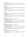
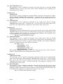
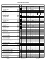
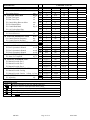
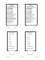
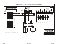
CONTROL LOGIC DESCRIPTION DOCUMENT
Configuration #: 6M70F0
Input/Output Table:
Inputs
Inside Temperature
Qty
4
Outputs
Variable Speed Stage
Single Speed Stage
Inlet
Curtain
Heater
Cooling Stage
Alarm
Qty
2
2
1
1
1
1
1
Equipment Required:
Item
Description
IC-610
Intelligent Control, 6 inputs / 10 outputs
CIP-1/6
Curtain Inlet Position
VPM-2
Variable Power Module 2 Outputs (10 Amperes)
2004-1K
Temperature Probe - Red (-6.0°F to 168.6°F)
Qty
1
1
1
4
Configuration Versions:
Version Date
Modification
F0
08/16/2006 New.
6M70F0
Page 1 of 16
08/25/2006
1. GENERAL
The IC-610 is a powerful control, which can be programmed to work in many types of buildings just by
changing the configuration logic. The configuration logic is the software that makes the relation between
the sensor readings, the parameters and the outputs. This software is stored in a chip identified with the
configuration number, as shown in the title of this document, and as it appears on your left hand side label
of your control. Please always provide this configuration number when you discuss with your provider.
To install properly and fully understand your IC-610, it is important to read both the IC-610 user’s
manual and this Control Logic Document. The user’s manual informs you on safety issues, warranty,
sensors, how to change parameters and many others characteristics of the IC-610, whereas this document
explains all particularities of this configuration logic. Section 2 explains what the user can control with
adjustable parameters while the section 3 contains information for the alarm.
Definition
Throughout this document, the following terminology is used.
- DRT →
Desired Room Temperature. This is the temperature goal for the room and it is
also the reference temperature for all relative settings. Note that the DRT is
affected by the growth curve function. See the user’s guide for more detail.
- RSP →
Relative Set Point. This is the number of degrees relative to the DRT where a
function begins.
- Differential →
Number of degrees changed before stopping the output. For example, with a
differential = 1.0°F, the IC-610 turns on a fan at 70.0°F when temperature
increases, but it will shut it off only at 69.0°F when the room is cooling down.
The differential is necessary to avoid oscillations.
- Modulation Band → Number of degrees a variable speed fan takes to reach its full speed.
Expressions in ITALICS are user’s parameters.
Ventilation System Overview
This configuration controls 2 variable speed stages, both of which can work off a minimum ventilation
timer when below their RSPs. There are 2 On/Off stages that run full time at maximum speed when above
their respective RSP. There is also an inlet that will open according to stage activation and a natural
curtain that will be controlled according to the temperature. A cooling output will be activated on a timer
when above its RSP. A heater output will be used when temperature is too low.
Refer to the building layout and the wiring schematics in attachment for a typical installation.
6M70F0
Page 2 of 16
08/25/2006
2. PARAMETER DESCRIPTION
Parameter # 1
ROOM TEMPERATURE
This parameter displays the average of the four temperature probes. All outputs will follow this
temperature. The ROOM TEMPERATURE is displayed to the nearest 0.1°F from -6.0°F to 168.6°F.
F3: See note 1.
Parameter # 2
DESIRED ROOM TEMPERATURE (DRT)
This parameter is used to establish the target room temperature. The DRT is used as the reference
point for other relative settings. When the GROWTH DAY is activated, the control takes charge of
this parameter so, to have access to this parameter, GROWTH DAY must be set to OFF. The DRT is
adjusted in 0.1°F increments from 32.0 °F to 120.0°F.
F2: ADJUST DAY (4 points)
This parameter is used to establish the days on the growth curve function. The ADJUST DAY is
adjusted in 1 day increments from day 1 to day 127. (For more details see User’s Manual).
F3: ADJUST TEMP (4 points)
This parameter associates a temperature value for each day defined on the growth day function. The
ADJUST TEMP is adjusted in 0.1°F increments from 32.0°F to 120.0°F. (For more details see User’s
Manual).
Parameters # 3-6
INSIDE TEMPERATURE 1-4
These parameters display the temperature of the respective temperature probe. The logic also checks
this parameter to determine if a temperature is too high or too low, at which point the alarm will be
activated. Each INSIDE TEMPERATURE is displayed to the nearest 0.1°F from -6.0°F to 168.6°F.
F3: See note 1.
Note1: In addition to the readout of the probe, the probe parameters can record the lowest and highest
values reached. To access the Hi/Lo recorded values, press F3 at the respective probe parameter.
To clear the respective Hi/Lo values, after pressing F3, press and hold the + and - buttons until
CLR appears on the LED display.
Parameters # 7
HEATER RSP
This parameter is used to establish the temperature RSP at which the heater begins to operate.
HEATER RSP is adjusted in 0.5°F increments from -10.0°F to 5.0°F.
F2: HEATER DIFF
This parameter is used to establish the differential of the heater output. The HEATER DIFF is
adjusted in 0.5°F increments from 0.5°F to 5.0°F.
Parameter # 8
FAN 1 RSP
This parameter is used to establish the temperature RSP at which fan 1 begins to modulate. When
ROOM TEMPERATURE reaches FAN 1 RSP, fan 1 will start to modulate from FAN 1 MIN SPEED
(at FAN 1 RSP) to finish at 100% (when temperature is at the end of FAN 1 MOD BAND). When the
ROOM TEMPERATURE is below FAN 1 RSP, fan 1 will run according to the minimum ventilation
timer at FAN 1 MIN SPEED. This parameter is adjusted in 0.5°F increments from -10.0°F to 30.0 °F.
6M70F0
Page 3 of 16
08/25/2006
F2: FAN 1 MIN SPEED
This parameter is used to establish the minimum speed of fan 1. When the ROOM TEMPERATURE
is below the FAN 1 RSP, fan 1 will run according to the minimum ventilation timer at minimum
speed. The FAN 1 MIN SPEED is adjusted in 1% increments from 12% to 100%.
F3: FAN 1 MOD BAND
This parameter is used to establish the range of temperature where fan 1 speeds up as ROOM
TEMPERATURE increases. Fan 1 increases its speed from its minimum speed (FAN 1 MIN SPEED
at FAN 1 RSP) to its maximum speed at the end of the FAN 1 MOD BAND. The FAN 1 MOD BAND
is adjusted in 0.5°F increments from 0.5°F to 10.0°F.
Parameter # 9
FAN 2 RSP
This parameter is used to establish the temperature RSP at which fan 2 begins to modulate. When
ROOM TEMPERATURE reaches FAN 2 RSP, fan 2 will start to modulate from FAN 2 MIN SPEED
(at FAN 2 RSP) to finish at 100% (when temperature is at the end of FAN 2 MOD BAND). When
ROOM TEMPERATURE is below FAN 2 RSP, fan 2 will run according to the minimum ventilation
timer at FAN 2 MIN SPEED if the FAN 2 ON TIMER option is set to ON. The FAN 2 RSP is
adjusted in 0.5°F increments from -10.0°F to 30.0 °F.
F2: FAN 2 MIN SPEED
This parameter is used to establish the minimum speed of fan 2. When ROOM TEMPERATURE is
below the FAN 2 RSP, fan 2 will run according to the minimum ventilation timer at minimum speed
if FAN 2 ON TIMER is set to ON. The FAN 2 MIN SPEED is adjusted in 1% increments from 12%
to 100%.
F3: FAN 2 MOD BAND
This parameter is used to establish the range of temperature where fan 2 speeds up as ROOM
TEMPERATURE increases. Fan 2 increases its speed from its minimum speed (FAN 2 MIN SPEED
at FAN 2 RSP) to its maximum speed at the end of the FAN 2 MOD BAND. The FAN 2 MOD BAND
is adjusted in 0.5°F increments from 0.5°F to 10.0°F.
Parameter # 10
MIN VENT TIMER DUTY CYCLE
This parameter is used to establish the cycle of a period of time for the minimum ventilation timer.
When ROOM TEMPERATURE is below the FAN 1-2 RSP, that fan will be activated during a cycle
of time (MIN VENT TIMER DUTY CYCLE) of a period (MIN VENT TIMER PERIOD). The MIN
VENT TIMER DUTY CYCLE is adjusted in 1% increments from 0% to 100%.
Ex: See MIN VENT TIMER PERIOD for example.
F2: MIN VENT TIMER PERIOD
This parameter is used to establish the period for the minimum ventilation timer. When ROOM
TEMPERATURE is below the FAN 1-2 RSP, that fan will be activated during a cycle of time (MIN
VENT TIMER DUTY CYCLE %) of a period (MIN VENT TIMER PERIOD). The MIN VENT TIMER
PERIOD is adjusted in 1 minute increments from 1 minute to 20 minutes.
Ex: DRT = 70.0°F
FAN # RSP = 2.0°F
MIN VENT TIMER DUTY CYCLE = 50%
MIN VENT TIMER PERIOD = 2 minutes
When inside temperature is below 72.0°F, Fan # will cycle ON 1 minute at minimum
speed and OFF 1 minute.
6M70F0
Page 4 of 16
08/25/2006
F3: FAN 2 ON TIMER
This parameter is used to determine if fan 2 will work off the minimum ventilation timer. If this
option is set to (1) YES, fan 2 will cycle on minimum ventilation timer when ROOM
TEMPERATURE is below its RSP. If this option is set to (0) NO, fan 2 will be inactive when
ROOM TEMPERATURE is below its RSP.
Parameter # 11
FAN 3 RSP
This parameter is used to establish the RSP at which fan 3 begins to operate. When ROOM
TEMPERATURE reaches DRT + FAN 3 RSP, fan 3 will be activated. The FAN 3 RSP is adjusted in
0.5°F increments from -10.0°F to 30.0°F.
F2: FAN 3 DIFF
This parameter is used to establish the differential for fan 3. When the ROOM TEMPERATURE
reaches DRT + FAN 3 RSP - FAN 3 DIFF, fan 3 will be deactivated. The FAN 3 DIFF is adjusted in
0.5°F increments from 0.5°F to 5.0°F.
Parameter # 12
FAN 4 RSP
This parameter is used to establish the RSP at which fan 4 begins to operate. When ROOM
TEMPERATURE reaches DRT + FAN 4 RSP, fan 4 will be activated. The FAN 4 RSP is adjusted in
0.5°F increments from -10.0°F to 30.0°F.
F2: FAN 4 DIFF
This parameter is used to establish the differential for fan 4. When the ROOM TEMPERATURE
reaches DRT + FAN 4 RSP - FAN 4 DIFF, fan 4 will be deactivated. The FAN 4 DIFF is adjusted in
0.5°F increments from 0.5°F to 5.0°F.
Parameter # 13
The inlet will close continously 1 minute after the curtain opens.
INLET POSITION FAN 1 MIN
This parameter is used to establish the position of the inlet when only fan 1 is running at its
minimum speed. The INLET POSITION FAN 1 MIN is adjusted in 1% increments from 0% to 100%.
F2: INLET POSITION FAN 1 MAX
This parameter is used to establish the position of the inlet when fan 1 is running at its maximum
speed (ROOM TEMPERATURE is equal to or above FAN 1 RSP + FAN 1 MOD BAND). The
INLET POSITION FAN 1 MAX is adjusted in 1% increments from 0% to 100%.
Parameter # 14
The inlet will close continously 1 minute after the curtain opens.
INLET POSITION FAN 2 MIN
This parameter is used to establish the position of the inlet when only fan 2 is running at its
minimum speed. The INLET POSITION FAN 2 MIN is adjusted in 1% increments from 0% to 100%.
F2: INLET POSITION FAN 2 MAX
This parameter is used to establish the position of the inlet when fan 2 is running at its maximum
speed (ROOM TEMPERATURE is equal to or above FAN 2 RSP + FAN 2 MOD BAND). The
INLET POSITION FAN 2 MAX is adjusted in 1% increments from 0% to 100%.
Parameter # 15
The inlet will close continously 1 minute after the curtain opens.
INLET POSITION FAN 3
This parameter is used to establish the position of the inlet when fan 3 is activated (ROOM
TEMPERATURE is equal to or above FAN 3 RSP). INLET POSITION FAN 3 is adjusted in 1%
increments from 0% to 100%.
6M70F0
Page 5 of 16
08/25/2006
F2: INLET POSITION FAN 4
This parameter is used to establish the position of the inlet when fan 4 is activated (ROOM
TEMPERATURE is equal to or above FAN 4 RSP). INLET POSITION FAN 4 is adjusted in 1%
increments from 0% to 100%.
Parameter # 16
COOLING RSP
This parameter is used to establish the temperature RSP at which the cooling begins to operate.
When the ROOM TEMPERATURE reaches DRT + COOLING RSP, the cooling output will be
activated according to its timer. The COOLING RSP is adjusted in 0.5°F increments from -20.0°F to
30.0°F.
F2: COOLING DIFF
This parameter is used to establish the differential for the cooling output. When the ROOM
TEMPERATURE reaches DRT + COOLING RSP - COOLING DIFF, the cooling output will be
deactivated. The COOLING DIFF is adjusted in 0.5°F increments from 0.5°F to 5.0°F.
Parameter # 17
COOLING DUTY CYCLE
This parameter is used to establish the active cycle of a period of time for the cooling. When ROOM
TEMPERATURE is equal to or above the COOLING RSP, cooling will be activated during a cycle
of time (COOLING DUTY CYCLE) of a period (COOLING PERIOD). The COOLING DUTY
CYCLE is adjusted in 1% increments from 0% to 100%.
Ex: See COOLING PERIOD for example.
F2: COOLING PERIOD
This parameter is used to establish the duration of the cooling period. When the ROOM
TEMPERATURE is above or equal to the COOLING RSP, cooling will be activated during a cycle
of time (COOLING DUTY CYCLE) of a period (COOLING PERIOD). The COOLING PERIOD is
adjusted in 1 minute increments from 1 minute to 20 minutes.
Ex: DRT = 70.0°F
COOLING RSP = 12.0°F
COOLING DIFF = 1.0°F
COOLING DUTY CYCLE = 10%
COOLING PERIOD = 10 minutes
When ROOM TEMPERATURE reaches 82.0°F, the cooling will cycle ON 1 minute and OFF 9
minutes. Cooling will deactivate when temperature drops to 81.0°F.
Parameter # 18
CURTAIN OPEN RSP
This temperature is used to adjust the temperature at which the curtain will stop closing and the
control exits natural mode. When the ROOM TEMPERATURE reaches DRT + CURTAIN OPEN
RSP + 0.3°F, the curtain will stop closing. The control exits natural mode when the ROOM
TEMPERATURE drops to DRT + CURTAIN OPEN RSP. This parameter is adjusted in 0.1°F
increments from -5.0°F to 20.0°F.
F2: RUN TIME OPEN
This parameter is used to establish the duration of the run time when the curtain opens. When
temperature rises to DRT + CURTAIN OPEN RSP + CURTAIN DEAD BAND, the curtain will open
during RUN TIME OPEN and will keep its position for CURTAIN DELAY BETWEEN MOVE. The
RUN TIME OPEN is adjusted in 1 second increments from 5 to 300 seconds.
Ex: See CURTAIN DEAD BAND for example.
6M70F0
Page 6 of 16
08/25/2006
F2: RUN TIME CLOSE
This parameter is used to establish the duration of the run time when the curtain closes. When
temperature drops to DRT + CURTAIN OPEN RSP, the curtain will close during RUN TIME CLOSE
and keep its position for CURTAIN DELAY BETWEEN MOVE. However, if ROOM
TEMPERATURE drops below DRT + HEATER RSP, the curtain will close continuously. The RUN
TIME CLOSE is adjusted in 1 second increments from 5 to 300 seconds.
Ex: See CURTAIN DEAD BAND for example.
F2: CURTAIN DELAY BETWEEN MOVE
This parameter is used to establish the time for which the curtain will not move when it is opening or
closing according to the curtain timer. The CURTAIN DELAY BETWEEN MOVE is adjusted in 1
minute increments from 1 minute to 10 minutes.
Ex: See CURTAIN DEAD BAND for example.
F2: FIRST NATURAL MOVE
This parameter is used to establish the time for which a curtain will open on the first opening cycle.
When temperature has fallen below DRT + CURTAIN OPEN RSP, the next opening cycle will use
FIRST NATURAL MOVE instead of RUN TIME OPEN. The FIRST NATURAL MOVE is adjusted in
1 second increments from 5 to 120 seconds.
Ex: See CURTAIN DEAD BAND for example.
F2: CURTAIN DEAD BAND
This parameter is used to establish the temperature range within which the curtain will not move.
When temperature is below DRT + CURTAIN OPEN RSP + CURTAIN DEAD BAND and above
DRT + CURTAIN OPEN RSP, the curtain will stay put. Above this range, curtain will open and
below this range, curtain will close. This parameter is adjusted in 0.1°F increments from 0.5°F to
2.0°F.
Ex: DRT = 70°F,
CURTAIN OPEN RSP = 7.0°F,
CURTAIN DEAD BAND= 2.0°F,
CURTAIN DELAY BETWEEN MOVE = 5 min,
FIRST NATURAL MOVE = 120 sec,
RUN TIME OPEN = 60 sec,
RUN TIME CLOSE = 120 sec,
HEATER RSP = -4.0°F.
- When the ROOM TEMPERATURE increases, the curtain will react as follows:
until 67.0°F: closes continuously.
between 67.0°F and 77.3°F: closes on a timer; close for 120 seconds and stay put for 5
minutes.
between 77.4°F and 78.9°F: does not move; this is the dead band.
at 79.0°F and up: opens on a timer; open for 120 seconds and stay put for 5 minutes on
the first cycle, then open for 60 seconds and stay put for 5 minutes for all other cycles.
- When the ROOM TEMPERATURE decreases, the curtain will react as follows:
until 78.7°F : opens on a timer; open for 60 seconds and stay put for 5 minutes.
between 78.7° F and 77.0°F: does not move; this is the dead band.
between 76.9°F and 67.0°F: closes on a timer; close for 120 seconds and stay put for 5
minutes.
at and below 67.0°F: closes continuously.
F2: # OF CYCLES TO STOP FANS
This parameter is used to adjust the number of open cycles (RUN TIME OPEN + CURTAIN DELAY
BETWEEN MOVE) it takes before the control enters natural mode and the fans shut down. # OF
CYCLES TO STOP FANS is adjusted in 1 cycle increments from 1 to 6 cycles.
6M70F0
Page 7 of 16
08/25/2006
Parameter # 19
ACCELERATED OPEN
This parameter is used to activate the accelerated open feature when the ROOM TEMPERATURE is
above DRT + CURTAIN OPEN RSP + CURTAIN DEAD BAND + 5.0°F. If this parameter is
adjusted to 1(yes), the RUN TIME OPEN will be increased by SECONDS INCREASE. The
ACCELERATED OPEN can be adjusted to 1(yes) or 0(no).
F2: SECONDS INCREASE
This parameter is used to adjust the amount of time that will be added to RUN TIME OPEN when
the ROOM TEMPERATURE is above DRT + CURTAIN OPEN RSP + CURTAIN DEAD BAND +
5.0°F. This parameter is adjusted in 1 second increments from 0 to 30 seconds.
Parameter # 20
CURTAIN EXERCISE CLOSE
This parameter is used to activate the curtain exercise feature that is used to remove the conditions
(water, rodents, etc.) that can cause premature curtain failure. If this parameter is set to ON, the
curtain will close for CURTAIN EXERCISE DURATION every time the CURTAIN EXERCISE
DAY COUNTER reaches the CURTAIN EXERCISE FREQUENCY. After the closing delay, if
the ROOM TEMPERATURE is above DRT + CURTAIN RSP + CURTAIN DEAD BAND, the
curtain will open for CURTAIN EXERCISE DURATION. Adjusting this parameter to 0(no) will reset
the day counter.
Ex: See CURTAIN EXERCISE FREQUENCY.
F2: CURTAIN EXERCISE FREQUENCY
This parameter is used to adjust the frequency at which the curtain exercise function will activate.
When the CURTAIN EXERCISE DAY COUNTER reaches this parameter, the curtains will close
for CURTAIN EXERCISE DURATION. If the temperature is still above DRT + CURTAIN OPEN
RSP + CURTAIN DEAD BAND, the curtain will open for CURTAIN EXERCISE DURATION. This
parameter is adjusted in 1 day increments from 1 to 100 days.
Ex: CURTAIN EXERCISE FREQUENCY = 60 days
CURTAIN EXERCISE DURATION = 3 minutes
- If the control is powered or the CURTAIN EXERCISE CLOSE is set to ON at 6:26pm,
every 60 days at 6:26pm the curtain will close for 3 minutes. After the closing delay, if
the ROOM TEMPERATURE is above DRT + CURTAIN RSP + CURTAIN DEAD
BAND, the curtain will open for 3 minutes.
F3: CURTAIN EXERCISE DURATION
This parameter is used to adjust the amount of time the curtain will open/close when the curtain
exercise occurs. This parameter is adjusted in 1 minute increments from 1 to 5 minutes.
Parameter # 21
CURTAIN EXERCISE DAY COUNTER
This parameter displays how many days have passed since the last curtain exercise. The curtain
exercise is done every CURTAIN EXERCISE FREQUENCY. This parameter is displayed to the
nearest day from 1 to 100 days.
Parameter # 22
FAN 1 OPERATION IN NATURAL
This parameter is used to activate or deactivate the fan 1 in natural mode. If this parameter is set to
ON, the fan 1 will be allowed to function in natural mode.
F2: FAN 2 OPERATION IN NATURAL
This parameter is used to activate or deactivate the fan 2 in natural mode. If this parameter is set to
ON, the fan 2 will be allowed to function in natural mode.
6M70F0
Page 8 of 16
08/25/2006
F2: FAN 3 OPERATION IN NATURAL
This parameter is used to activate or deactivate the fan 3 in natural mode. If this parameter is set to
ON, the fan 3 will be allowed to function in natural mode.
F2: FAN 4 OPERATION IN NATURAL
This parameter is used to activate or deactivate the fan 4 in natural mode. If this parameter is set to
ON, the fan 4 will be allowed to function in natural mode.
Parameter # 23
ALARM HI TEMP RSP
This parameter is used to establish the temperature RSP at which a high temperature alarm condition
will occur. When the ROOM TEMPERATURE is greater than DRT + ALARM HI TEMP RSP, an
alarm will occur. The ALARM HI TEMP RSP is adjusted in 0.1°F increments from 0.0°F to 40.0°F.
See also the alarm section 3 for other alarm conditions.
F2: ALARM LO TEMP RSP
This parameter is used to establish the temperature RSP at which a low temperature alarm condition
will occur. When the ROOM TEMPERATURE is lesser than DRT + ALARM LO TEMP RSP, an
alarm will occur. The ALARM LO TEMP RSP is adjusted in 0.1°F increments from -20.0°F to 1.0°F.
See also the alarm section 3 for other alarm conditions.
Parameter # 24
MANUAL OVERRIDE FAN 1
F2: MANUAL OVERRIDE FAN 2
These parameters are used to control manually the respective fan (1-2). When this parameter is set to
AUTO, the respective fan (1-2) will follow the configuration logic. When this parameter is set to 0,
the respective fan (1-2) will be deactivated. When this parameter is set to a value between 1 and 100,
the respective fan (1-2) will run at the corresponding speed.
F2: MANUAL OVERRIDE FAN 3
F2: MANUAL OVERRIDE FAN 4
These parameters are used to control manually the respective fan (3-4). When this parameter is set to
AUTO, the respective fan (3-4) will follow the configuration logic. When this parameter is set to 0,
the respective fan (3-4) will be deactivated. When this parameter is set to ON, the respective (3-4)
will be activated.
Parameter # 25
MANUAL OVERRIDE HEATER
These parameters are used to control manually the heater. When this parameter is set to AUTO, the
heater will follow the configuration logic. When this parameter is set to 0, the heater will be
deactivated. When this parameter is set to ON, the heater will be activated.
F2: MANUAL OVERRIDE COOLING
These parameters are used to control manually the cooling. When this parameter is set to AUTO, the
cooling will follow the configuration logic. When this parameter is set to 0, the cooling will be
deactivated. When this parameter is set to ON, the cooling will be activated.
F3: MANUAL OVERRIDE CURTAIN
These parameters are used to control manually the curtain. When this parameter is set to AUTO, the
curtain will follow the configuration logic. When this parameter is set to 0, the curtain will stp
moving. If the parameter is set to 1, the curtain will close and when this parameter is set to open, the
curtain will be open.
Parameter # 26
GROWTH DAY
This parameter is used to program the current day of the growth curve function. The GROWTH
DAY is adjusted in 1 day increments from day 1 to day 127. (For more details see User’s Manual).
6M70F0
Page 9 of 16
08/25/2006
F2: ADJUST DAY
This is to adjust the growth day. Growth day can be turned OFF, or adjusted to any day value from 1
to 127.
6M70F0
Page 10 of 16
08/25/2006
3. ALARM
The alarm relay is normally activated, but it will deactivate 2.6 seconds or more after a power failure or
after one of the following events occurs:
a. IC-610 is defective.
b. ROOM TEMPERATURE exceeds the limits ALARM HI or LO TEMP RSP.
c. ROOM TEMPERATURE is defective; open/short circuited, varies more than 20.0°F in a
one-minute period.
ATTACHMENTS
•
•
•
6M70F0
Parameter Table
Labels
Wiring Diagram
Page 11 of 16
08/25/2006
PARAMETER TABLE
DESCRIPTION
CONTROL VALUES
*
1. ROOM TEMPERATURE
F2: Probe Input #
F3: Hi/Lo
2. DESIRED ROOM TEMP
F2: Adjust Day
F3: Adjust Temperature
3. INSIDE TEMP 1
F2: Probe Input #
F3: Hi/Lo
4. INSIDE TEMP 2
F2: Probe Input #
F3: Hi/Lo
5. INSIDE TEMP 3
F2: Probe Input #
F3: Hi/Lo
6. INSIDE TEMP 4
F2: Probe Input #
deg F
MIN
-6.0
MAX
168.6
PRESET
*****
deg. F
-6.0
168.6
PRB 1-4
deg. F CLR
deg. F
day
none
deg. F none
deg F
-6.0
32.0
1
32.0
-6.0
168.6
120.0
127
120.0
168.6
*****
75.0
1
78.0
*****
deg. F
-6.0
168.6
PRB 1
deg. F CLR
deg F
-6.0
-6.0
168.6
168.6
*****
*****
deg. F
-6.0
168.6
PRB 2
deg. F CLR
deg F
-6.0
-6.0
168.6
168.6
*****
*****
deg. F
-6.0
168.6
PRB 3
deg. F CLR
deg F
-6.0
-6.0
168.6
168.6
*****
*****
deg. F
-6.0
168.6
PRB 4
-6.0
-10.0
0.5
-10.0
12
0.5
-10.0
12
0.5
0
1
0
-10.0
0.5
-10.0
0.5
0
0
0
0
0
0
-20.0
0.5
168.6
5.0
5.0
30.0
100
10.0
30.0
100
10.0
100
20
1
30.0
5.0
30.0
5.0
100
100
100
100
100
100
30.0
5.0
*****
-2.0
1.0
0.0
50
2.0
2.0
50
2.0
100
5
0
4.0
1.0
5.0
1.0
10
20
30
40
60
100
15.0
1.0
F3: Hi/Lo
deg. F
7. HEATER RSP
deg. F
F2: Heater Diff
deg. F
8. FAN 1 RSP
deg. F
F2: Fan 1 Min Speed
%
F3: Fan 1 Mod Band
deg. F
9. FAN 2 RSP
deg. F
F2: Fan 2 Min Speed
%
F3: Fan 2 Mod Band
deg. F
10. MIN VENT TIMER DUTY CYCLE %
F2: Min Vent Timer Period
min
F3: Fan 2 On Timer
0(no), 1(yes)
11. FAN 3 RSP
deg. F
F2: Fan 3 Diff
deg. F
12. FAN 4 RSP
deg. F
F2: Fan 4 Diff
deg. F
13. INLET POSITION FAN 1 MIN
%
F2: Inlet Position Fan 1 Max
%
14. INLET POSITION FAN 2 MIN
%
F2: Inlet Position Fan 2 Max
%
15. INLET POSITION FAN 3
%
F2: Inlet Position Fan 4
%
16. COOLING RSP
deg. F
F2: Cooling Diff
deg. F
6M70F0
CLR
none
none
none
none
none
none
none
none
none
none
none
none
none
none
none
none
none
none
none
none
none
none
none
Page 12 of 16
10
75.0
20
70.0
08/25/2006
30
65.0
DESCRIPTION
17. COOLING DUTY CYCLE
F2: Cooling Period
18. CURTAIN OPEN RSP
F2: Run Time Open
F2: Run Time Close
F2: Curtain Delay Between Move
F2: First Natural Move
F2: Curtain Dead Band
F2: # of Cycle to Stop Fans
19. ACCELERATED OPEN
F2: Seconds Increase
20. CURTAIN EXERCISE CLOSE
F2: Curtain Exercise Frequency
F3: Curtain Exercise Duration
21. CURT. EXE. DAY COUNTER
CONTROL VALUES
*
none
%
min
none
deg. F none
sec
none
sec
none
min
none
sec
none
deg. F none
none
0=no none
sec
none
0=no none
day
none
min
none
day
22. FAN 1 OPERATION IN NATURAL on/off
F2: Fan 2 Operation in Natural
on/off
F2: Fan 3 Operation in Natural
on/off
F2: Fan 4 Operation in Natural
on/off
23. ALARM HI TEMP RSP
deg. F
F2: Alarm Lo Temp RSP
deg. F
24. MANUAL OVERRIDE FAN 1
F2: Manual Override Fan 2
F2: Manual Override Fan 3
F2: Manual Override Fan 4
25. MANUAL OVERRIDE HEATER
F2: Manual Override Cooling
F3: Manual Override Curtain 0=Stop, 1=Close
26. GROWTH DAY
day
F2: Adjust day
day
none
none
none
none
none
none
none
none
none
none
none
none
none
none
MIN
0
1
-5.0
5
5
1
5
0.5
1
0
0
1
1
1
OFF, 1
MAX
100
20
20.0
300
300
10
120
2.0
6
1
30
0
100
5
100
PRESET
10
20
7.0
20
40
3
30
1.0
2
1
10
1
60
3
60
OFF
OFF
OFF
OFF
0.0
-20.0
AUTO, 0
AUTO, 0
AUTO, 0
AUTO, 0
AUTO, 0
AUTO, 0
AUTO, 0
OFF
OFF
ON
ON
ON
ON
40.0
1.0
100
100
ON
ON
ON
ON
1, OPEN
127
127
ON
OFF
OFF
OFF
15.0
-7.0
AUTO
AUTO
AUTO
AUTO
AUTO
AUTO
AUTO
OFF
OFF
* Restriction legend
None
Parameter adjustable by the user and the supervisor
Invisible to the user when supervisor mode is OFF
Read only to the user when supervisor mode is OFF
Follow a growth curve when ramping function is ON
Cannot be changed
CLR
simultaneously to clear
Press
6M70F0
Page 13 of 16
08/25/2006
6M70F0
6M70F0
1 Room Temperature
2 Desired Room Temp. (DRT)
3-6 Inside Probe 1-4
7 Heater Settings
8 Fan 1 Settings
9 Fan 2 Settings
10 Min Vent Settings
11 Fan 3 Settings
12 Fan 4 Settings
13-15 Inlet Position Settings
16-17 Cooling Settings
18 Curtain Settings
19 Accelerated Open
20 Curtain Exercise Settings
21 Curt. Exercise Day Counter
22 Fan # Operation in Nat
23 Alarm Settings
24-25 Manual Override
26 Growth Day
1 Room Temperature
2 Desired Room Temp. (DRT)
3-6 Inside Probe 1-4
7 Heater Settings
8 Fan 1 Settings
9 Fan 2 Settings
10 Min Vent Settings
11 Fan 3 Settings
12 Fan 4 Settings
13-15 Inlet Position Settings
16-17 Cooling Settings
18 Curtain Settings
19 Accelerated Open
20 Curtain Exercise Settings
21 Day Counter
22 Fan # Operation in Nat
23 Alarm Settings
24-25 Manual Override
26 Growth Day
1
Curtain Open
1
Curtain Open
2
Curtain Close
2
Curtain Close
3
Fan 1
3
Fan 1
4
Fan 2
4
Fan 2
5
Fan 3
5
Fan 3
6
Fan 4
6
Fan 4
7
Heater
7
Heater
8
Cooling
8
Cooling
9
Curtain Exercise
9
Curtain Exercise
10 Natural Mode
6M70F0
10 Natural Mode
Page 14 of 16
08/25/2006
WIRING DIAGRAM CONFIGURATION 6M70F0
PWR/8VAC
GND
INTELLIGENT COMPUTER
THE IC-610 MUST BE ON
AN INDEPENDENT CIRCUIT
IC-610
1059E
THESE MODULES MUST
BE ON SAME PHASE
10 AND LINE VOLTAGE
THAN THE IC-610
WARNING!!!
5
7
PRB 5 PRB 6
PRB 1 PRB 2 PRB 3 PRB 4 4-20mA 4-20mA
MGCB
P0
P1
P3
P2
4
4
ALARM
NC C NO
P4
4
4
SET LINE VOLTAGE
230V
TO CORRECT VALUE BEFORE
ATTEMPTING TO OPERATE
THE COMPUTER.
LINE VOLTAGE
SELECTOR
6
REL 1 REL 2 REL 3 REL 4 REL 5
REL 6
NO C NO C NO C NO C NO C NO C NC
LINE
115V/230V
+
8
9
L2/N
TEMP. PROBE 4
L2/N
10
VPM-2
LINE
CURRENT
VOLTAGE DETECTOR
L2/N
L1
L2/N
L1
L2/N
L1
L2/N
L1
L2/N
L1
6A @ 120/240VAC
½HP @ 240V
¼HP @ 115V
OPN
CONTROL MODULE
CLO
CIP-1/6
VARIABLE SPEED
MODULE
10A @ 120/240VAC
CLOSE OPEN
FAN 2
FAN 1
2004-1K
INLET
L2/N
L1
SEE NOTES ON NEXT PAGE
L1
10
COM
TEMP. PROBE 3
TEMP. PROBE 2
TEMP. PROBE 1
L1
L2/N
R
COM
L1
Varifan
L2/N
L2/N
WIRING DIAGRAM
DRAW
L1
L1
04/08/06
Yanick Alain
CONFIGURATION
6M70F0
6M70F0
Page 15 of 16
FILE
/DIAGIC/6M70F0
WIR
REV
0
08/25/2006
6M70F0
Electrician’s notes
Wiring tips and hints (see guide for details)
1
(PROBE WIRING) SHIELDED WIRE AWG #18 WITH 16/30 STRANDING, 500FT/150M
MAXIMUM LENGTH. (Ex.: DECA 73-310)
For other probe, refer to specific probe manual for appropriate maximum length and wire size
or use AWG #18, 500FT/150M MAXIMUM LENGTH (whichever is shorter).
2
(COMMUNICATION WIRING) SHIELDED LOW CAPACITANCE WIRE, (Capacitance
between conductors @ 1Khz = 24PF/FT), TWISTED PAIR (8 twist/FT), AWG #18 TO 22,
750 FT/250 M MAX LENGTH. (Ex.: BELDEN 8761)
3
HIGH VOLTAGE WIRE INSTALLED ACCORDING TO LOCAL WIRING CODE.
4
INSTALL LOW VOLTAGE WIRES (PROBES, COMPUTER LINK OR
POTENTIOMETER WIRES) AT LEAST 12 INCHES (30cm) AWAY FROM HIGH
VOLTAGE WIRES (120/230VAC, 24VDC). ALWAYS CROSS HIGH AND LOW
VOLTAGE WIRES AT A 90-DEGREE ANGLE.
5
RELAYS: 10A @ 250VAC RESISTIVE, MOTOR 1HP @ 250VAC, 1/2HP 120VAC AT
EACH OUTPUT (OUT 1-6)
6
MAXIMUM 2 WIRES OF SAME SIZE PER BLACK TERMINAL, NO BIGGER THAN
AWG #12, NO SMALLER THAN AWG #22.
7
1 WIRE ONLY PER GREEN TERMINAL. USE WIRE CONNECTOR IF YOU WANT TO
CONNECT MORE THAN 1 WIRE.
8
CHECK INSTALLATION GUIDE FOR ALARM WIRING.
9
USE SHIELD FOR SHIELDING PURPOSE ONLY. CONNECT THE SHIELD TO THE
CONTROL CIRCUIT COMMON END ONLY . NEVER LEAVE THE SHIELD
UNCONNECTED AT BOTH ENDS. NEVER CONNECT BOTH ENDS OF THE SHIELD
TO COMMON . THE USE OF A SHIELD FOR ALL PROBES AND
POTENTIOMETERS IS MANDATORY.
10
THESE MODULES MUST BE ON SAME POWER PHASE AND LINE VOLTAGE AS
THE CONTROLLER.
6M70F0
Page 16 of 16
08/25/2006